pmp-25 pump load control installation, set up ... - Load Controls Inc
pmp-25 pump load control installation, set up ... - Load Controls Inc
pmp-25 pump load control installation, set up ... - Load Controls Inc

Create successful ePaper yourself
Turn your PDF publications into a flip-book with our unique Google optimized e-Paper software.
PMP-<strong>25</strong> PUMP LOAD CONTROL<br />
INSTALLATION, SET UP AND ADJUSTMENT<br />
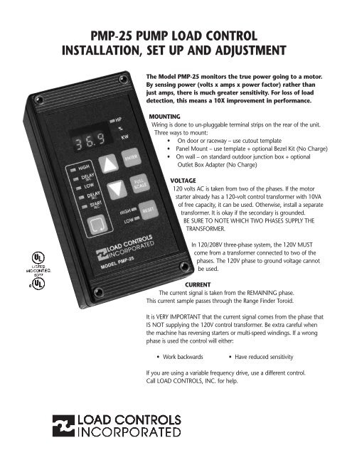
The Model PMP-<strong>25</strong> monitors the true power going to a motor.<br />
By sensing power (volts x amps x power factor) rather than<br />
just amps, there is much greater sensitivity. For loss of <strong>load</strong><br />
detection, this means a 10X improvement in performance.<br />
MOUNTING<br />
Wiring is done to un-pluggable terminal strips on the rear of the unit.<br />
Three ways to mount:<br />
� On door or raceway – use cutout template<br />
� Panel Mount – use template + optional Bezel Kit (No Charge)<br />
� On wall – on standard outdoor junction box + optional<br />
Outlet Box Adapter (No Charge)<br />
VOLTAGE<br />
120 volts AC is taken from two of the phases. If the motor<br />
starter already has a 120-volt <strong>control</strong> transformer with 10VA<br />
of free capacity, it can be used. Otherwise, install a separate<br />
transformer. It is okay if the secondary is grounded.<br />
BE SURE TO NOTE WHICH TWO PHASES SUPPLY THE<br />
TRANSFORMER.<br />
In 120/208V three-phase system, the 120V MUST<br />
come from a transformer connected to two of the<br />
phases. The 120V phase to ground voltage cannot<br />
be used.<br />
CURRENT<br />
The current signal is taken from the REMAINING phase.<br />
This current sample passes through the Range Finder Toroid.<br />
It is VERY IMPORTANT that the current signal comes from the phase that<br />
IS NOT s<strong>up</strong>plying the 120V <strong>control</strong> transformer. Be extra careful when<br />
the machine has reversing starters or multi-speed windings. If a wrong<br />
phase is used the <strong>control</strong> will either:<br />
� Work backwards � Have reduced sensitivity<br />
If you are using a variable frequency drive, use a different <strong>control</strong>.<br />
Call LOAD CONTROLS, INC. for help.
MODEL<br />
PMP-<strong>25</strong><br />
+ -<br />
4-20<br />
MA OUTPUT<br />
REMOTE RESET<br />
LOW TRIP<br />
REMOTE<br />
HIGH<br />
FULL SCALE CAPACITY AT 460 VOLTS<br />
The Range Finder Toroid has six motor size choices. Select one that<br />
is equal or larger than your motor. This will leave some headroom.<br />
• For motors less than 5 HP (460 volt), take extra turns.<br />
• For motors greater than 50 HP, use Range Finder Toroid<br />
+ Current Transformer.<br />
MOTOR FULL SCALE %FULL RANGE TURNS CURRENT<br />
SIZE CAPACITY LOAD FINDER TRANS-<br />
SWITCH FORMER<br />
1/2 HP .6 HP 123 2 ON 8<br />
1 1.<strong>25</strong> 123 2 ON 4<br />
1-1/2 1.65 109 2 ON 3<br />
2 2.70 134 2 ON 2<br />
3 3.80 128 3 ON 2<br />
5 5.50 110 2 ON 1<br />
7-1/2 8.<strong>25</strong> 110 3 ON 1<br />
10 11.0 110 4 ON 1<br />
15 27.5 183 5 ON 1<br />
20 27.5 137 5 ON 1<br />
<strong>25</strong> 27.5 110 5 ON 1<br />
30 55.0 183 6 ON 1<br />
40 55.0 138 6 ON 1<br />
50 55.0 110 6 ON 1<br />
60 84.0 140 1 ON 1 100:5<br />
75 84.0 112 1 ON 1 100:5<br />
100 130 130 1 ON 1 150:5<br />
1<strong>25</strong> 130 104 1 ON 1 150:5<br />
150 173 115 1 ON 1 200:5<br />
200 216 108 1 ON 1 <strong>25</strong>0:5<br />
<strong>25</strong>0 260 104 1 ON 1 300:5<br />
300 346 115 1 ON 1 400:5<br />
LOW<br />
TRIP<br />
RELAY OUTPUTS —<br />
POWER ON, NOT TRIPPED<br />
HIGH<br />
TRIP<br />
1 2 3 4 5 6 7 8 9 10 11 12 13 14 15 16<br />
MOTOR<br />
RANGE FINDER<br />
TOROID<br />
CURRENT FROM<br />
REMAINING PHASE<br />
VOLTAGE<br />
TRANSFORMER<br />
WITH 120V<br />
SECONDARY<br />
MOTOR STARTER<br />
MULTIPLIERS<br />
For nominal voltages<br />
other than 460 volts,<br />
multiply 460V full scale by:<br />
208V = .45<br />
230V = .5<br />
380V = .83<br />
415V = .9<br />
575V = 1.<strong>25</strong><br />
For Kilowatts<br />
multiply Full Scale HP x .746<br />
For motor sizes or capacities<br />
not in table:<br />
%Full <strong>Load</strong> = Full Scale Capacity x 100<br />
Your Motor Size
FOR MOTORS LESS THAN 5 HP<br />
Take more “turns” of the leg through the Toroid. Each time<br />
the wire passes through the Toroid is a “turn”.<br />
This<br />
is<br />
one<br />
turn.<br />
RANGE FINDER TOROID<br />
3 1/2"<br />
2"<br />
This<br />
is<br />
two<br />
turns.<br />
FOR MOTORS GREATER THAN 50 HP<br />
A Current Transformer is used to reduce the primary current.<br />
The 5-amp secondary passes through the Toroid.<br />
Pass secondary of CT through toroid.<br />
CAUTION<br />
2 3/8"<br />
1 1/8" Hole<br />
When current is flowing through the primary of<br />
the external current transformer, always have a<br />
wire between the two brass Terminals on the CT.<br />
If they are left open, dangerous and destructive<br />
voltages can develop.<br />
HOOKING UP THE RESET<br />
Control can be re<strong>set</strong> three ways:<br />
� Manually with the Re<strong>set</strong> button on the <strong>control</strong>.<br />
� Remotely with a remotely located re<strong>set</strong> button or relay.<br />
� Automatic with a jumper.<br />
Remote Re<strong>set</strong>-<br />
Momentarily connect Terminal 4 to Terminal 6 for low<br />
Momentarily connect Terminal 5 to Terminal 6 for high<br />
Automatic Re<strong>set</strong>-<br />
Jumper Terminal 4 or 5 to Terminal 6<br />
The terminals for Re<strong>set</strong> generate a small amount of current<br />
(8-12 milliamps). To re<strong>set</strong>, you just need to connect the terminal<br />
to the circuit common (Terminal 6).<br />
The switches or relays that you use must be suitable for low<br />
current (Gold flashed contacts, Reed Relays, Mercury Switches).<br />
4-20 MILLIAMP ANALOG OUTPUT<br />
The Analog Output is directly proportional to Full Scale<br />
capacity. It is always active. 500 ohm maximum connected<br />
impedance.<br />
Terminal 2 4-20mA Positive<br />
Terminal 3 4-20mA Negative<br />
Use twisted pair or in noisy environments, use shielded cable.<br />
Ground shield at other end.<br />
Use the Full Scale capacity from the chart to scale external<br />
meter, chart recorders or computers.<br />
THE PMP-<strong>25</strong> POWERS THE 4-20MA SIGNAL.<br />
DON’T USE AN EXTERNAL DC POWER SUPPLY.<br />
SPECIFICATIONS PMP-<strong>25</strong><br />
ENCLOSURE<br />
Glass-filled Polycarbonate<br />
NEMA 4, 4X - STYLE<br />
(3 1/4" x 6 1/4" x 2")<br />
(83 mm x 160 mm x 54 mm)<br />
CAPACITY<br />
To 50 horsepower directly<br />
through Toroid<br />
To 500 horsepower with external<br />
Current Transformer & Toroid<br />
DIGITAL LOAD DISPLAY<br />
.4" LED 3 Digit<br />
RELAY OUTPUTS<br />
Latch when tripped<br />
(2) Form C 3 AMP @ 300 VAC or<br />
1/8 HP @ 240 VAC<br />
Size 2 starter maximum (directly)<br />
ANALOG OUTPUT<br />
4-20mA; powered by the<br />
PMP-<strong>25</strong> 500 OHM<br />
maximum connected impedance<br />
RESPONSE TIME<br />
500 Milliseconds<br />
TEMPERATURE<br />
0˚C - 55˚C<br />
TIMERS<br />
Start-<strong>up</strong> – 0-999 seconds<br />
(16.7 minutes) adjustable<br />
Low Trip Delay – 0-999 seconds<br />
(16.7 minutes) adjustable<br />
High Trip Delay – 0-999 seconds<br />
(16.7 minutes) adjustable
TO SET FULL SCALE<br />
� After hook-<strong>up</strong>, find your HP, KW or % from the chart.<br />
� Decide if you want to display HP, % or KW.<br />
FULL<br />
� The SCALE cycles through the choices shown below and<br />
blinks slowly for each choice. Each press of FULL moves<br />
SCALE<br />
you to the next choice.<br />
ADJUSTMENTS<br />
SET POINT - HIGH: The HIGH relay will switch when the <strong>load</strong><br />
is above the HIGH.<br />
SET POINT - LOW: The LOW relay will switch when the <strong>load</strong><br />
is below the LOW.<br />
Start-<strong>up</strong> Timer<br />
The Start-<strong>up</strong> Timer bypasses the Control during motor start<strong>up</strong><br />
to avoid false trips because of current inrush. For convenience,<br />
the TIMING BEGINS WHEN THE MOTOR STARTS.<br />
The Start-<strong>up</strong> LED stays lit until the start-<strong>up</strong> period is over.<br />
The start-<strong>up</strong> time should be:<br />
� Long enough so that the <strong>load</strong> has stabilized.<br />
Delay Timers<br />
To avoid nuisance trips from short over<strong>load</strong>s, Delay Timers<br />
bypass the Control for the selected time. The relays won’t trip<br />
until the time is exceeded. If the trip condition goes away<br />
before the time is <strong>up</strong>, the timer re<strong>set</strong>s to zero.<br />
� Start with minimum Delay. If you are getting trips<br />
where you don’t want them, increase the Delay Time.<br />
FRONT PANEL SET-UP TIPS<br />
1) None of the <strong>set</strong>tings will be changed until you hold<br />
down and the fast blinking stops.<br />
2) Five seconds after you have pressed a button, the <strong>control</strong><br />
will return to normal operation.<br />
3) If you hold down the digits will continue to change.<br />
FULL<br />
4) You only need to do when you install the PMP-<strong>25</strong><br />
(or if you change the hook-<strong>up</strong>).<br />
DIGITS –––> DECIM AL –––> DECIM AL –––> DECIM AL –––> HP –––> % –––> KW<br />
XXX. XX.X X.XX<br />
–––><br />
to change if this is if this is if this is if this is if this is if this is<br />
your choice, your choice, your choice, your choice, your choice, your choice,<br />
press press press press press press<br />
–––><br />
–––><br />
ENTER ENTER ENTER ENTER ENTER ENTER ENTER<br />
until fast until fast until fast until fast until fast until fast until fast<br />
blink stops blink stops blink stops blink stops blink stops blink stops blink stops<br />
–––><br />
ENTER<br />
–––><br />
TO VIEW AND CHANGE THE SET POINTS<br />
AND DELAY TIMES<br />
cycles through the choices. The LED for each choice<br />
will turn ON.<br />
To change a <strong>set</strong>ting, use<br />
SCALE<br />
–––><br />
–––><br />
Press ENTER until quick blinking stops to store your new<br />
choice.<br />
After 5 seconds if you haven’t pressed any buttons, <strong>control</strong><br />
will return to normal operation.<br />
ADJUSTMENT TIPS FOR CENTRIFUGAL PUMPS<br />
From Pump Curves<br />
Use the recommended minimum and maximum flows and<br />
horsepower for your initial <strong>set</strong> points.<br />
–OR–<br />
Actual Operation<br />
Low Trip - Run the <strong>pump</strong> with the OUTLET valves closed.<br />
This is the minimum flow. Set the low trip about here.<br />
High Trip - Run the <strong>pump</strong> with all valves wide open.<br />
This is the maximum flow. Set the high trip about here.<br />
� Make adjustments if you get nuisance trips<br />
53 Technology Park Road | Sturbridge, MA 01566 | ph: 888-600-3247 | fx: 508-347-2064 | <strong>load</strong><strong>control</strong>s.com<br />
03/2008