05618- Manual for 50-100 lb. Carbon Dioxide - Amerex Corporation
05618- Manual for 50-100 lb. Carbon Dioxide - Amerex Corporation
05618- Manual for 50-100 lb. Carbon Dioxide - Amerex Corporation

Create successful ePaper yourself
Turn your PDF publications into a flip-book with our unique Google optimized e-Paper software.
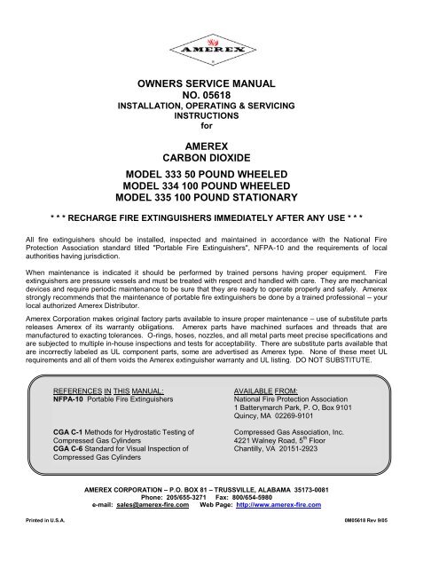
OWNERS SERVICE MANUAL<br />
NO. <strong>05618</strong><br />
INSTALLATION, OPERATING & SERVICING<br />
INSTRUCTIONS<br />
<strong>for</strong><br />
AMEREX<br />
CARBON DIOXIDE<br />
MODEL 333 <strong>50</strong> POUND WHEELED<br />
MODEL 334 <strong>100</strong> POUND WHEELED<br />
MODEL 335 <strong>100</strong> POUND STATIONARY<br />
* * * RECHARGE FIRE EXTINGUISHERS IMMEDIATELY AFTER ANY USE * * *<br />
All fire extinguishers should be installed, inspected and maintained in accordance with the National Fire<br />
Protection Association standard titled "Portable Fire Extinguishers", NFPA-10 and the requirements of local<br />
authorities having jurisdiction.<br />
When maintenance is indicated it should be per<strong>for</strong>med by trained persons having proper equipment. Fire<br />
extinguishers are pressure vessels and must be treated with respect and handled with care. They are mechanical<br />
devices and require periodic maintenance to be sure that they are ready to operate properly and safely. <strong>Amerex</strong><br />
strongly recommends that the maintenance of portable fire extinguishers be done by a trained professional – your<br />
local authorized <strong>Amerex</strong> Distributor.<br />
<strong>Amerex</strong> <strong>Corporation</strong> makes original factory parts available to insure proper maintenance – use of substitute parts<br />
releases <strong>Amerex</strong> of its warranty obligations. <strong>Amerex</strong> parts have machined surfaces and threads that are<br />
manufactured to exacting tolerances. O-rings, hoses, nozzles, and all metal parts meet precise specifications and<br />
are subjected to multiple in-house inspections and tests <strong>for</strong> acceptability. There are substitute parts available that<br />
are incorrectly labeled as UL component parts, some are advertised as <strong>Amerex</strong> type. None of these meet UL<br />
requirements and all of them voids the <strong>Amerex</strong> extinguisher warranty and UL listing. DO NOT SUBSTITUTE.<br />
REFERENCES IN THIS MANUAL: AVAILABLE FROM:<br />
NFPA-10 Portable Fire Extinguishers National Fire Protection Association<br />
1 Batterymarch Park, P. O, Box 9101<br />
Quincy, MA 02269-9101<br />
CGA C-1 Methods <strong>for</strong> Hydrostatic Testing of Compressed Gas Association, Inc.<br />
Compressed Gas Cylinders 4221 Walney Road, 5 th Floor<br />
CGA C-6 Standard <strong>for</strong> Visual Inspection of Chantilly, VA 20151-2923<br />
Compressed Gas Cylinders<br />
AMEREX CORPORATION – P.O. BOX 81 – TRUSSVILLE, ALABAMA 35173-0081<br />
Phone: 205/655-3271 Fax: 800/654-5980<br />
e-mail: sales@amerex-fire.com Web Page: http://www.amerex-fire.com<br />
Printed in U.S.A. 0M<strong>05618</strong> Rev 9/05
LIMITED WARRANTY<br />
<strong>Amerex</strong> warrants its fire extinguishers to be free from defects in material and workmanship <strong>for</strong> a period of six (6)<br />
years from the date of purchase. During the warranty period, any such defects will be repaired or the defective<br />
extinguisher replaced if the original grey lockwire seal is intact and/or if only factory replacement parts and<br />
recommended service equipment have been used to service the extinguisher. This warranty does not cover<br />
defects resulting from the modification, alteration, misuse, exposure to unusually corrosive conditions nor<br />
improper installation or maintenance. All implied warranties, including but not limited to, warranties of fitness <strong>for</strong><br />
purpose and merchantability, are limited to the time periods as stated above. In no event shall <strong>Amerex</strong><br />
<strong>Corporation</strong> be liable <strong>for</strong> incidental or consequential damages. Some states do allow limitations on how long an<br />
implied warranty lasts or the exclusion or limitation of incidental or consequential damages, so that the above<br />
limitations or exclusions may no apply to you. <strong>Amerex</strong> <strong>Corporation</strong> neither assumes nor authorizes any<br />
representative or other person to assume <strong>for</strong> it any obligation or liability other than as expressly set <strong>for</strong>th herein.<br />
This warranty gives you specific legal rights, and you may also have other rights which vary from state to state.<br />
To obtain per<strong>for</strong>mance of the obligation of this warranty, write to <strong>Amerex</strong> <strong>Corporation</strong>, P. O. Box 81, Trussville, AL<br />
35173-0081 <strong>for</strong> instructions.<br />
THIS MANUAL IS ATTACHED TO EVERY NEW EXTINGUISHER SHIPPED FROM THE FACTORY. IT<br />
CONTAINS VALUABLE INFORMATION WHICH SHOULD BE STUDIED BY EVERYONE WHO WILL USE OR<br />
SERVICE THE EXTINGUISHER. THE MANUAL SHOULD BE STORED IN A CONVENIENT LOCATION FOR<br />
EASY REFERENCE.<br />
PREPARING YOUR NEW EXTINGUISHER FOR USE<br />
1. Remove all wrappings, straps and pallet retaining bolts.<br />
2. Examine the extinguisher <strong>for</strong> shipping damage.<br />
3. Remove shipping cap(s) from CO2 cylinder(s). Install discharge hose (<strong>50</strong> <strong>lb</strong>.) or manifold (<strong>100</strong> <strong>lb</strong>.) to<br />
cylinder valve(s). check to insure that the hose connection to the operating valve/or manifold and hose to<br />
the squeeze grip shut-off valve are tight.<br />
4. Check to insure that the cylinder valve(s) are in the CLOSED position. The ring (locking) pin should be<br />
installed and the lockwire seal intact.<br />
5. Visually inspect the safety relief on the cylinder valve <strong>for</strong> evidence of obstruction or damage. DO NOT<br />
REMOVE.<br />
6. This extinguisher is shipped from the factory fully charged. The most accurate method to determine if the<br />
extinguisher is filled with the proper amount of Caron <strong>Dioxide</strong> is to weigh the unit. The gross weight is<br />
indicated on the lower right hand corner of the pictogram operation INSTRUCTIONS (plus weight of<br />
cylinders stamped on cylinder valve{s}),<br />
7. Record the date the unit is being placed into service on the inspection tag and attach it to the<br />
extinguisher.<br />
INSTALLATION<br />
Do not place this extinguisher close to a potential fire hazard. <strong>Amerex</strong> recommends location no less than a<br />
20 foot distance from the hazard while leaving an unobstructed access. Avoid placing it in an extremely hot<br />
or cold place. The operational temperature range <strong>for</strong> this extinguisher is –40°F to 120°F (-40°C to 49°C).<br />
The extinguisher should be adequately protected if temperatures outside of this range are anticipated. Keep<br />
the extinguisher clean and free from dirt, ice, chemicals and any contaminants that may interfere with its<br />
proper operation. DO NOT FUNCTIONALLY TEST THIS FIRE EXTINGUISHER. (Testing or any use may<br />
cause the extinguisher to gradually lose extinguishing agent over a period of time and make the extinguisher<br />
ineffective.)<br />
OPERATION<br />
WARNING: HIGH CONCENTRATIONS OF CARBON DIOXIDE CAN CAUSE RESPIRATORY<br />
PROBLEMS. SELF CONTAINED BREATHING APPARATUS OR AIR LINE RESPIRATORS<br />
SHOULD BE USED IF OXYGEN LEVEL HAS BEEN DIMINISHED BELOW 19%. AVOID<br />
SKIN CONTACT – CO2 IS VERY COLD AND COULD CAUSE BURNS OR FROSTBITE.<br />
CAUTION: Persons expected to use this extinguisher should be trained in initiating its operation<br />
and in the proper fire fighting technique. "Hands on" training will prepare personnel<br />
with the feel <strong>for</strong> this extinguisher so that the most effective application can be utilized in<br />
an emergency situation. The basic operating instructions are contained in the<br />
pictogram portion of every extinguisher nameplate (label). The following elaborates on<br />
these instructions.<br />
1
1. Move the extinguisher (wheeled unit) to within approximately 10 feet (<strong>50</strong> <strong>lb</strong>.), 30 feet (<strong>100</strong> <strong>lb</strong>.) of the fire<br />
site.<br />
2. Twist and pull ring pin(s). Pull “T” handle cylinder valve lever(s) to open cylinder valve. Pull hose from<br />
rack. Start back 10 feet from the fire.<br />
3. Grasp horn squeeze grip shut-off valve and aim horn at base of fire nearest you.<br />
4. Squeeze horn shut-off valve lever. Sweep side to side across the base of the fire and past both edges.<br />
Progressively follow up until the fire is extinguished. Work the fire away from you while being alert <strong>for</strong><br />
flashbacks. Move closer as the fire is extinguished but not so close as to scatter or splash the burning<br />
material.<br />
5. When the fire is out, release the horn shut-off valve lever to stop discharge. Stand by and watch <strong>for</strong><br />
possible re-ignition.<br />
6. Evacuate and ventilate the area immediately after extinguishing the fire. The fumes and smoke from any<br />
fire may be hazardous and can be deadly.<br />
<strong>50</strong> LB. <strong>100</strong> LB.<br />
Discharge Time (approx.) 44 seconds ±5 sec. 74 seconds ±8 sec.<br />
Hose Length 15 feet 40 feet<br />
BEFORE PREPARING TO MOVE THE EXTINGUISHER TO THE RECHARGE LOCATION<br />
DETERMINATION MUST BE MADE THAT THE FIRE IS COMPLETELY EXTINGUISHED AND THERE IS<br />
NO DANGER OF A FLASHBACK.<br />
HAVE EXTINGUISHER RECHARGED IMMEDIATELY AFTER ANY USE<br />
SHUTDOWN<br />
1. Push cylinder valve “T” handle(s) to the closed position and install ring (locking) pin. Squeeze nozzle<br />
shut-off valve to release any carbon dioxide remaining in the hose.<br />
2. When all pressure has been evacuated from the hose, remove hose (<strong>50</strong> <strong>lb</strong>.) or manifold (<strong>100</strong> <strong>lb</strong>.) from<br />
cylinder valve(s). Install shipping cap(s) to protect valve assembly. Coil the extinguisher hose onto the<br />
storage rack and position the nozzle onto the mount in preparation <strong>for</strong> transport to the recharge location.<br />
AMEREX CORPORATION DOES NOT SERVICE, MAINTAIN OR RECHARGE FIRE EXTINGUISHERS. THIS<br />
MANUAL IS PUBLISHED AS A GUIDE TO ASSIST QUALIFIED SERVICE PERSONNEL IN THE INSPECTION,<br />
MAINTENANCE AND RECHARGE OF AMEREX FIRE EXTINGUISHERS ONLY. NO INSTRUCTION MANUAL<br />
CAN ANTICIPATE ALL POSSIBLE MALFUNCTIONS THAT MAY BE ENCOUNTERED IN THE SERVICE OF<br />
FIRE EXTINGUISHERS. DUE TO THE POSSIBILITY THAT PRIOR SERVICE PERFORMED ON THIS<br />
EQUIPMENT MAY HAVE BEEN IMPROPERLY DONE, IT IS EXTREMELY IMPORTANT THAT ALL<br />
WARNINGS, CAUTIONS AND NOTES IN THIS MANUAL BE CAREFULLY OBSERVED. FAILURE TO HEED<br />
THESE INSTRUCTIONS COULD RESULT IN SERIOUS INJURY.<br />
AMEREX ASSUMES NO LIABILITY FOR SERVICE, MAINTENANCE OR RECHARGE OF FIRE EXTINGUISHERS BY PUBLISHING<br />
THIS MANUAL.<br />
INSPECTING THE EXTINGUISHER<br />
INSPECTION [NFPA-10] is a "quick check" that a fire extinguisher is available and is in operating condition. It is<br />
intended to give reasonable assurance that the fire extinguisher is fully charged. This is done by verifying that it is<br />
in its designated place, that it has not been actuated or tampered with, and that there is no obvious physical<br />
damage or condition to prevent its operation.<br />
PERIODIC INSPECTION PROCEDURES<br />
(monthly or more often if circumstances dictate)<br />
2
[NFPA-10] A “quick check” should be made of the extinguisher <strong>for</strong> the following:<br />
1. Located in designated place<br />
2. No obstruction to access or visibility<br />
3. Operating instructions on nameplate legible and facing outward<br />
4. Seals and tamper indicators not broken or missing<br />
5. Determine fullness by weighing<br />
6. Examination <strong>for</strong> obvious physical damage, corrosion, leakage, or clogged nozzle or horn<br />
7. obstruction<br />
8. Condition of tires, carriage and hose<br />
MAINTENANCE<br />
Maintenance [NFPA 10] At least once a year (or more frequently if indicated by an inspection) Maintenance<br />
should be per<strong>for</strong>med. Maintenance is a thorough examination of the fire extinguisher. It is intended to give<br />
maximum assurance that a fire extinguisher will operate effectively and safely. It includes a thorough examination<br />
<strong>for</strong> physical damage or condition to prevent its operation and any necessary repair or replacement. It will<br />
normally reveal if hydrostatic testing or internal maintenance is required.<br />
MAINTENANCE PROCEDURE<br />
NOTE: This procedure will be best accomplished with the extinguisher in an upright position on a level<br />
surface.<br />
1. Clean extinguisher to remove dirt, grease or <strong>for</strong>eign material. Check to make sure that the instruction<br />
nameplate and UL manifest are securely fastened and legible. Inspect the cylinder <strong>for</strong> corrosion,<br />
abrasion, dents or weld damage. If any of these conditions are found and you doubt the integrity of the<br />
cylinder, hydrostatically test to factory test pressure, using the proof pressure method in accordance with<br />
CGA C-6 and NFPA 10. Properly dispose of cylinder if in violation of the standard.<br />
2. Inspect the extinguisher <strong>for</strong> damaged, missing or substitute parts. Only factory replacement parts are<br />
approved <strong>for</strong> use on <strong>Amerex</strong> fire extinguishers.<br />
3. Check the date of manufacture on the extinguisher cylinder dome. Cylinder must be hydrostatically<br />
tested every 5 years to the test pressure indicated on the nameplate (3000 psi [20.69 MPa]).<br />
Note: Complete maintenance should be per<strong>for</strong>med whenever a hydrostatic test is being done. This<br />
includes an inspection of the interior of the valve assembly, the spring and valve stem assembly, as well<br />
as the interior of the cylinder.<br />
4. Remove ring (locking) pin and check <strong>for</strong> freedom of movement. Replace if bent or if removal appears<br />
difficult.<br />
5. Check the horn shutoff lever <strong>for</strong> freedom of movement (squeeze and release several times). If the<br />
operation is impeded, disassemble the nozzle, replace parts and/or properly lubricate as necessary.<br />
Make sure that the horn is clear and unobstructed.<br />
WARNING: SQUEEZE HORN SHUT-OFF LEVER SLOWLY. CARBON DIOXIDE MAY HAVE BEEN<br />
LEFT IN THE HOSE FROM A PREVIOUS DISCHARGE. BE PREPARED FOR A POSSIBLE<br />
DISCHARGE AND NOZZLE RECOIL.<br />
6. Remove the hose and horn and inspect <strong>for</strong> damage. Replace the hose if cut or cracked, or if threaded<br />
couplings are damaged. Replace the horn if brittle, cracked or de<strong>for</strong>med. Blow air through the hose and<br />
nozzle assemblies to insure that the passage is clear of <strong>for</strong>eign material.<br />
CAUTION: <strong>Carbon</strong> dioxide hose assemblies have a continuous metal braid that connects to both<br />
couplings to minimize static shock. A hose continuity test should be per<strong>for</strong>med using a basic conductivity<br />
3
tester consisting of a flashlight having an open circuit and a set of two wires with a conductor (clamps or<br />
probe) at each end. (NFPA-10 Appendix A).<br />
NOTE: <strong>Carbon</strong> dioxide hose assemblies require hydrostatic testing every 5 years to the same test<br />
pressure as the cylinder (3000 psi [20.69 MPa]).<br />
7. Inspect cylinder valve assembly <strong>for</strong> corrosion or damage to hose thread connection. Visually inspect the<br />
safety disc assembly <strong>for</strong> obstruction or damage. Valve removal and/or valve part replacement should be<br />
made only after completely discharging the contents of the cylinder.<br />
8. Inspect the wheels to insure they rotate freely. Lubricate as required.<br />
9. Check carriage assembly <strong>for</strong> loose nuts, bolts, frame distortion or damage. Check welds <strong>for</strong> damage or<br />
corrosion. Replace damaged parts or make repairs as necessary.<br />
10. Reinstall horn to shut-off valve and valve to hose. Reconnect the hose to the agent cylinder. Properly<br />
coil the hose on the rack and horn in the clips.<br />
11. Weigh extinguisher and compare with weight printed on the Pictogram operating instruction on the label<br />
(plus the weight of the cylinder(s) stamped on the cylinder valve(s). recharge extinguisher if weight is not<br />
within indicated allowable tolerances (more than 5 <strong>lb</strong>s. per cylinder).<br />
12. Install new tamper seal and record service data on the extinguisher inspection tag.<br />
13. If the extinguisher has been moved to per<strong>for</strong>m service, make sure that it is returned to its proper location.<br />
RECHARGE<br />
RECHARGING [NFPA-10] is the replacement of the extinguishing agent .<br />
RECHARGING PROCEDURE<br />
WARNING: Be<strong>for</strong>e attempting to recharge be sure the extinguisher is completely empty and depressurized. Use<br />
only an approved source of carbon dioxide (see minimum specifications in NFPA-10 Chapter 4 Inspection,<br />
Maintenance and Recharging). Do not use dry ice converters. Use an approved pump, hose and recharge<br />
adapter to insure safe and efficient recharge operations.<br />
1. Per<strong>for</strong>m steps 1 thru 10 of the Maintenance procedure.<br />
2. Discharge all remaining carbon dioxide from the extinguisher.<br />
NOTE: The Model 334 & 335 (<strong>100</strong> <strong>lb</strong>.) extinguishers have two <strong>50</strong> <strong>lb</strong>. cylinders manifolded to a<br />
common discharge hose. The manifold must be removed be<strong>for</strong>e attempting to recharge the<br />
cylinders.<br />
3. Place <strong>50</strong> <strong>lb</strong>. cylinder on an accurate scale (the full weight – cylinder, valve and CO2 is stamped on the<br />
valve). Install recharge adapter. Connect carbon dioxide supply line to the recharge adapter.<br />
4. Move “T” handle on the cylinder valve to the open position and pump <strong>50</strong> <strong>lb</strong>s. (22.7 KG) of clean, dry<br />
carbon dioxide into the cylinder.<br />
5. When the proper weight is reached, move the “T” handle on the cylinder valve to the closed position.<br />
Shut off CO2 pump and vent supply line.<br />
6. Remove the CO2 supply line and recharge adapter from the cylinder valve. .<br />
7. Check <strong>for</strong> leaks using leak detection fluid or a solution of soapy water. If any leaks occur, refer to the<br />
Troubleshooting Guide.<br />
8. Install ring (locking) pin and lockwire seal on cylinder valve(s). Attach new recharge tag.<br />
9. Install cylinder(s) to the carriage and properly secure.<br />
10. Attach the hose and horn assembly to the cylinder valve. Install hose and horn assembly on carriage.<br />
4
CAUTION: The Models 334 and 335 extinguishers have two <strong>50</strong> <strong>lb</strong>. cylinders manifolded to a<br />
common discharge hose. Properly align the cylinders, then attach manifold hoses with manifold and<br />
discharge hose and horn assembly to the cylinder valves.<br />
11. Weigh assembled extinguisher and confirm that the total weight is within the allowable tolerances<br />
indicated on the pictogram operating instructions (plus weight of cylinder[s] stamped on cylinder valve[s]).<br />
5
TROUBLE SHOOTING GUIDE<br />
WARNING: BEFORE ATTEMPTING TO CORRECT ANY LEAKAGE PROBLEM, BE SURE THAT THE<br />
CYLINDER AND HOSE ARE COMPLETELY EMPTY AND DEPRESSURIZED.<br />
NOTE: Check to determine the source of a leak be<strong>for</strong>e the extinguisher is emptied. Leakage repairs will<br />
require that the <strong>Carbon</strong> <strong>Dioxide</strong> cylinder be completely empty and the valve assembly removed. When<br />
reinstalling the cylinder valve assembly, the cylinder must be placed in a suitable securing vice and valve<br />
installed to 1<strong>50</strong> ft. <strong>lb</strong>s. of torque.<br />
1.<br />
2.<br />
3.<br />
4.<br />
5.<br />
6.<br />
PROBLEM CORRECTIVE ACTION<br />
Leak at valve to cylinder<br />
Remove valve assembly, install new Teflon sealing tape, reinstall valve<br />
connection<br />
to a maximum of 1<strong>50</strong> ft. <strong>lb</strong>s. torque.<br />
Leak through valve Remove valve assembly, downtube, spring and valve stem assembly.<br />
Install new valve stem assembly. Check valve seat <strong>for</strong> scratches or<br />
<strong>for</strong>eign matter.<br />
Leak at safety relief nut Remove safety nut, disc and gasket assembly. Replace with new<br />
<strong>Amerex</strong> P/N 04000 safety nut, disc and gasket assembly. Tighten<br />
assembly to 2<strong>50</strong> in. <strong>lb</strong>s. of torque.<br />
Leak at base of “T” handle on Remove valve assembly, downtube, spring and valve cylinder stem<br />
valve.<br />
assembly. Install new valve stem assembly. Check valve seat <strong>for</strong><br />
scratches or <strong>for</strong>eign matter.<br />
Leak at any hose connections Tighten hose connections and check <strong>for</strong> hose coupling damage.<br />
Replace hose assembly as necessary.<br />
Leak in the cylinder Contact <strong>Amerex</strong> if under warranty, otherwise mark “REJECTED” and<br />
return to owner.<br />
NOTE: When valve removal is per<strong>for</strong>med at hydrotest, the cylinder neck threads must be examined per<br />
CGA C-6. “Cylinders shall be rejected if the required number of effective threads is materially reduced so<br />
that a gas tight seal cannot be obtained by reasonable valving methods. Common defects are worn or<br />
corroded crests and broken or nicked threads.”<br />
6
Item Part<br />
No. No. Description<br />
1 09891 Carriage Asy w/o wheels – 333<br />
1A 09903 Carriage Asy w/o wheels – 334 1<br />
1B 17209 Frame Asy - 335<br />
2 09618 Pictogram – 333<br />
2A 09787 Pictogram – 334<br />
2B 17304 Pictogram – 335<br />
10234 Wheel Asy – 16” w/hubcap, washers<br />
3<br />
& retaining pin-full pneumatic<br />
07751 “ -semi pneumatic 1<br />
3A 04945 Hub Cap 1<br />
Std.<br />
Pkg.<br />
4 12470 Cap – Valve Protector 1<br />
5 06373<br />
Valve Lever (“T” handle w/roll pin<br />
& knobs)<br />
6 04000 Safety Disc, Gasket & Nut Asy 6<br />
7 09897 Valve Stem Asy 6<br />
8 00<strong>50</strong>1 Spring 6<br />
9 09627 Retainer 1<br />
10 09623 Downtube 1<br />
11 06<strong>100</strong> Ring Pin, Stainless Steel w/Wire 12<br />
1<br />
1<br />
1<br />
1<br />
12 01387 Lockwire Seal (Yellow) <strong>50</strong>0<br />
13 09895 Valve Asy Complete w/downtube 1<br />
14 17301 Plastic Plug 2<br />
15 09892 Horn Clip w/Mounting Hardware 1<br />
16<br />
16A<br />
17<br />
17A<br />
18<br />
09893<br />
09904<br />
09380<br />
09396<br />
09365<br />
09545<br />
Cyl Restraining (Saddle) straps<br />
w/ Mounting Hardware – 333<br />
“ -334 & 335<br />
Horn Holder – 333<br />
“ - 334 &335<br />
Hose Asy – 333 – 15 ft.<br />
Hose Asy – 334 & 335 – 40 ft.<br />
19 09366 Shut-off Valve Asy 1<br />
20 09899 Vlv Stem Asy <strong>for</strong> Shut-off Valve 6<br />
21 09901 Spring <strong>for</strong> Shut-off Valve 6<br />
22 09896 Handle w/Rubber Cover 1<br />
23 09369 Horn & Nozzle 1<br />
24 08169 Union (Manifold) – 334 & 335 1<br />
25 09905 Manifold (w/Union) – 334 & 335 1<br />
1<br />
1<br />
1<br />
1<br />
1<br />
7<br />
PARTS LIST<br />
<strong>for</strong><br />
<strong>50</strong> and <strong>100</strong> <strong>lb</strong>. <strong>Carbon</strong> <strong>Dioxide</strong><br />
Extinguishers<br />
Model 333 - <strong>50</strong> <strong>lb</strong>.<br />
Model 334 – <strong>100</strong> <strong>lb</strong>. (Two <strong>50</strong> <strong>lb</strong>. Cylinders)<br />
Model 335 – <strong>100</strong> <strong>lb</strong>. Stationary