Floor/Ceiling Assemblies - Steel Framing - National Gypsum Company
Floor/Ceiling Assemblies - Steel Framing - National Gypsum Company
Floor/Ceiling Assemblies - Steel Framing - National Gypsum Company

Create successful ePaper yourself
Turn your PDF publications into a flip-book with our unique Google optimized e-Paper software.
1 Hour<br />
Design #<br />
Link to .PDF file<br />
Link to .DWG file<br />
Link to .DWG/Text file<br />
1 Hour<br />
Design #<br />
Link to .PDF file<br />
Link to .DWG file<br />
Link to .DWG/Text file<br />
1 Hour<br />
Link to .PDF file<br />
Link to .DWG file<br />
Link to .DWG/Text file<br />
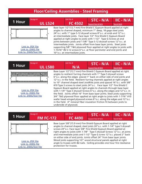
<strong>Floor</strong>/<strong>Ceiling</strong> <strong>Assemblies</strong> - <strong>Steel</strong> <strong>Framing</strong><br />
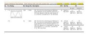
UL L524<br />
UL L580<br />
Design #<br />
FM FC-172<br />
GA File #<br />
FC 4502<br />
STC - N/A IIC - N/A<br />
Sound Test # N/A Test # N/A<br />
Base layer 1/2”(12.7 mm) Fire-Shield C <strong>Gypsum</strong> Board applied at right<br />
angles to channel shaped, minimum 7” deep, 18 gage steel joists<br />
24”o.c. with 1” type S-12 drywall screws 8”o.c. at ends and 12”o.c.<br />
at intermediate joists. Face layer 1/2” Fire-Shield C <strong>Gypsum</strong> Board<br />
applied at right angles to joists with 1-1/2” Type G Screws at end<br />
joints between joists and 1-5/8” Type S-12 drywall screws 12”o.c. at<br />
intermediate joists. Joints offset from base layer joints. <strong>Steel</strong> joists<br />
supporting 5/8” T&G plywood floor applied at right angles to joists with<br />
1-15/16” #6 S-12 screws 6”o.c. at floor perimeter and end joints and<br />
10”o.c. at intermediate joists.<br />
GA File #<br />
N/A<br />
STC - N/A IIC - N/A<br />
Sound Test # N/A Test # N/A<br />
Base Layer 1/2”(12.7 mm) Fire-Shield C <strong>Gypsum</strong> Board applied at right<br />
angles to resilient furring channels with 1” Type S drywall screws<br />
6”o.c. along the edges placed 1” back on either side of end joints and<br />
12”o.c. in the field. Resilient furring channels applied at right angles<br />
to 10” channel shaped steel JoistRite joists and spaced 16”o.c. with 5/8”<br />
#10 Type S screws to steel joists 24”o.c. Face layer 1/2” Fire-Shield C<br />
<strong>Gypsum</strong> Board applied at right angles to channels through base layer<br />
with 1-1/4” Type S drywall Screws 6”o.c. along the edges and 12”o.c. in<br />
the field. Joints offset 16” from base layer joints. <strong>Steel</strong> joists supporting<br />
3/4” T&G plywood floor applied at right angle to joists with 1-7/16” #10<br />
wafer head winged plywood screws 6”o.c. along the edges and 12”o.c.<br />
in the field. 4” mineral fiber insulation friction fit between joists to<br />
underside of plywood.<br />
GA File #<br />
FC 4490<br />
STC - N/A IIC - N/A<br />
Sound Test # N/A Test # N/A<br />
Base Layer 5/8”(15.9 mm) Fire-Shield <strong>Gypsum</strong> Board applied at right<br />
angles to channel shaped, steel joists 24”o.c. with 1-1/4” type S drywall<br />
screws 24”o.c. Face layer 5/8” Fire-Shield <strong>Gypsum</strong> Board applied at<br />
right angles to joists with 1-7/8” Type S drywall Screws 12”o.c. at joints<br />
and intermediate joists and 1-1/2” Type G screw 12”o.c. placed 2” back<br />
on either side of end joints. Joints offset 24” from base layer joints.<br />
Wood joists supporting 1/2” wood structural panels applied at right<br />
angle to trusses with 8d nails. <strong>Ceiling</strong> provides one hour fire resistance<br />
protection for trusses.<br />
2008 ~ <strong>National</strong> <strong>Gypsum</strong> <strong>Company</strong> Party Walls
1 Hour<br />
1.5 Hour<br />
2 Hour<br />
Design #<br />
Link to .PDF file<br />
Link to .DWG file<br />
Link to .DWG/Text file<br />
Design #<br />
Link to .PDF file<br />
Link to .DWG file<br />
Link to .DWG/Text file<br />
Design #<br />
Link to .PDF file<br />
Link to .DWG file<br />
Link to .DWG/Text file<br />
<strong>Floor</strong>/<strong>Ceiling</strong> <strong>Assemblies</strong> - <strong>Steel</strong> <strong>Framing</strong><br />
UL L565<br />
UL L527<br />
UL L556<br />
GA File #<br />
FC 4515<br />
GA File # STC - N/A IIC - N/A<br />
Sound Test # N/A Test # N/A<br />
Base Layer 5/8”(15.9 mm) Fire-Shield C <strong>Gypsum</strong> Board applied at right<br />
angles to resilient furring channels with 1” Type S screws 24”o.c.<br />
Resilient furring channels applied at right angles to channel shaped<br />
steel joists and spaced 16”o.c. with 1/2” Type S-12 screws to steel joists<br />
24”o.c. Face layer 5/8” Fire-Shield C <strong>Gypsum</strong> Board applied at right<br />
angles to channels through base layer with 1-5/8” Type S drywall Screws<br />
12”o.c. Edge joints offset 16” from base layer joints. Butt joints of face<br />
layer to occur between resilient channels with 1-1/2” type G screws<br />
spaced 8”o.c. attached to base layer. <strong>Steel</strong> joists supporting 3/4” T&G<br />
plywood floor applied at right angle to joists<br />
GA File #<br />
FC 4750<br />
STC - N/A IIC - N/A<br />
Sound Test # N/A Test # N/A<br />
5/8”(15.9 mm) Fire-Shield C <strong>Gypsum</strong> Board applied at right angles to<br />
resilient furring channels 12”o.c. when insulation is used and 16”o.c.<br />
without insulation. <strong>Gypsum</strong> board attached with 1-1/8” type S drywall<br />
screws 12”o.c. <strong>Gypsum</strong> board end joints attached with screws 12”o.c.<br />
to additional pieces of channel 60” long located 3” back on either side<br />
of end joints. Resilient furring channels applied at right angles to light<br />
gage steel trusses spaced 48”o.c. with 1/2” Type S-12 screws. <strong>Steel</strong><br />
trusses supporting 23/32” wood structural panels applied at right angle<br />
to trusses with construction adhesive and mechanical fasteners 12”o.c.<br />
and 15/32” wood structural panel underlayment applied at right angles<br />
to trusses with mechanical fasteners 12”o.c. Joints staggered between<br />
underlayment and subfloor.<br />
STC - N/A IIC - N/A<br />
Sound Test # N/A Test # N/A<br />
Base Layer 5/8”(15.9 mm) Fire-Shield <strong>Gypsum</strong> Board applied at right<br />
angles to 8”steel joists 24”o.c. with 1-1/4” Type S-12 drywall screws<br />
12”oc. Second layer 5/8” Fire-Shield <strong>Gypsum</strong> Board applied at right<br />
angles to joists with 2” Type S-12 drywall Screws 12”o.c. Joints<br />
staggered 24” from base layer. Third layer 5/8” Fire-Shield <strong>Gypsum</strong><br />
Board applied at right angles to joists with 2-1/2” Type S-12 drywall<br />
Screws 12”o.c. Joints staggered 12” from second layer. Rigid furring<br />
channels applied at right angles to joists over third layer with two<br />
2-1/2” Type S-12 drywall Screws at each joist. Face layer 5/8” Fire-<br />
Shield <strong>Gypsum</strong> Board applied at right angles to furring channels with<br />
1-1/8”Type S drywall Screws 12”o.c. <strong>Steel</strong> joists supporting 3/4” T&G<br />
plywood floor applied at right angle to joists with #10x1-5/8”screws<br />
12”o.c. along joists.<br />
2008 ~ <strong>National</strong> <strong>Gypsum</strong> <strong>Company</strong> Party Walls