Gypsum Board Systems - National Gypsum Company
Gypsum Board Systems - National Gypsum Company
Gypsum Board Systems - National Gypsum Company

You also want an ePaper? Increase the reach of your titles
YUMPU automatically turns print PDFs into web optimized ePapers that Google loves.
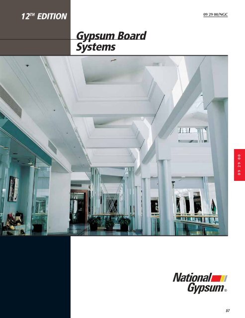
12 TH EDITION<br />
<strong>Gypsum</strong> <strong>Board</strong><br />
<strong>Systems</strong><br />
09 29 00/NGC<br />
®<br />
57<br />
09 29 00
Gold Bond ® BRAND <strong>Gypsum</strong> <strong>Board</strong> Products<br />
<strong>National</strong> <strong>Gypsum</strong> <strong>Company</strong><br />
features a wide variety of<br />
gypsum board products<br />
and accessories including<br />
regular gypsum board, Fire-<br />
Shield fire resistant board,<br />
1/4" High Flex <strong>Gypsum</strong><br />
<strong>Board</strong>, 1/2" High Strength<br />
Ceiling <strong>Gypsum</strong> <strong>Board</strong>, Hi-<br />
Impact <strong>Gypsum</strong> <strong>Board</strong>,<br />
Gridstone Ceiling <strong>Board</strong>s,<br />
<strong>Gypsum</strong> Sheathing, Fire-<br />
Shield Shaftliner, Durasan<br />
Prefinished <strong>Gypsum</strong> <strong>Board</strong>,<br />
Exterior Soffit <strong>Board</strong>, and<br />
Joint Treatment products.<br />
DESCRIPTION<br />
GOLD BOND ®<br />
GOLD BOND ®<br />
GOLD BOND ®<br />
GOLD BOND ®<br />
GOLD BOND ®<br />
GOLD BOND ®<br />
GOLD BOND ®<br />
GOLD BOND ®<br />
BRAND WALLBOARD<br />
BRAND WALLBOARD<br />
BRAND WALLBOARD<br />
BRAND WALLBOARD<br />
BRAND WALLBOARD<br />
BRAND WALLBOARD<br />
BRAND WALLBOARD<br />
BRAND WALLBOARD<br />
58 NATIONAL GYPSUM BOARD PRODUCTS<br />
Our concentration isn’t on<br />
building products alone,<br />
however. At the <strong>National</strong><br />
<strong>Gypsum</strong> Research and<br />
Testing Center, we develop<br />
complete construction systems.<br />
In such systems,<br />
products are evaluated<br />
together as complete building<br />
assemblies–walls, partitions,<br />
floors and ceilings.<br />
We have included in this section<br />
details and application<br />
instructions for many of<br />
those assemblies: Steel<br />
Frame Partitions, Steel<br />
Frame Ceilings/Furring<br />
Channels or Studs, Wood<br />
1/<br />
1/2<br />
1/2"<br />
1/2" x<br />
1/2" x 1/2"<br />
8' T<br />
x 1/2"<br />
8'<br />
x 1/2"<br />
8<br />
x 8<br />
Description Core Thickness/Type Width/Edge Lengths<br />
Gold Bond BRAND <strong>Gypsum</strong><br />
<strong>Board</strong> with tapered edge<br />
permits smooth joint<br />
treatment; surface takes any<br />
decoration. Basic<br />
recommendations:<br />
1/2" board for single layer;<br />
3/8" board for 2-layer; 1/4"<br />
board is regular gypsum<br />
board used in remodeling and<br />
for sound control in double<br />
layer applications. Refer to<br />
page 65.<br />
Gold Bond BRAND XP <strong>Gypsum</strong><br />
<strong>Board</strong> is designed to provide<br />
extra protection against mold<br />
and mildew compared to standard<br />
gypsum board products.<br />
Tapered edge permits smooth<br />
joint treatment. Refer to page<br />
70.<br />
Gold Bond BRAND Fire-Shield<br />
<strong>Gypsum</strong> <strong>Board</strong> is manufactured<br />
with a type X core to<br />
achieve fire resistance ratings<br />
when used in recommended<br />
systems. Refer to page 66.<br />
Gold Bond BRAND Fire-Shield C<br />
<strong>Gypsum</strong> <strong>Board</strong> has a specially<br />
formulated type X core to<br />
achieve superior performance<br />
when used in specific fire<br />
rated assemblies. May be used<br />
in designs requiring Fire-Shield<br />
<strong>Gypsum</strong> <strong>Board</strong> (type X core).<br />
Refer to page 66.<br />
Frame Wall and Ceilings,<br />
<strong>Gypsum</strong> <strong>Board</strong> Over Foam<br />
Insulated Masonry and<br />
Solid Laminated Partitions.<br />
Before a <strong>National</strong> <strong>Gypsum</strong><br />
System is released to the<br />
building industry, it is thoroughly<br />
tested, and results are<br />
correlated and charted to<br />
make it easier for the builder<br />
or specifier to match a system<br />
to their needs or to the<br />
building codes.<br />
The drywall construction systems<br />
referred to in this catalog<br />
are designed primarily<br />
with materials manufactured<br />
by <strong>National</strong> <strong>Gypsum</strong><br />
<strong>Company</strong>. Substitution of<br />
any product or other<br />
brands in a tested system<br />
is not recommended.<br />
Field installation of tested systems<br />
must be identical to<br />
laboratory installation to<br />
produce optimum performance<br />
of these systems.<br />
Performance tests are conducted<br />
in accordance with<br />
accepted national standards<br />
under controlled laboratory<br />
conditions to minimize<br />
variances and to permit<br />
comparison of test<br />
results with all types of systems,<br />
similar and dissimilar.<br />
Regular 1/4" (6.3 mm) 4' (1219 mm) 6' (1828 mm)<br />
3/8" (9.5 mm) Square thru<br />
1/2" (12.7 mm)* or 16' (4876 mm)<br />
Tapered<br />
Note: 1/2" gypsum board available in 54" widths.<br />
Regular 1/2" (12.7 mm) 4' (1219 mm) 8' (2438 mm)<br />
Square 10' (3048 mm)<br />
or 12' (3657 mm)<br />
Tapered<br />
Type X 5/8" (15.9 mm) FSW* 4' (1219 mm) 6' (1828 mm)<br />
Square thru<br />
or<br />
Tapered<br />
16' (4876 mm)<br />
Type X 1/2" (12.7 mm) FSW-C 4' (1219 mm) 6' (1828 mm)<br />
Square thru<br />
or<br />
Tapered<br />
16' (4876 mm)<br />
Type X 5/8" (15.9 mm) FSW-C 4' (1219 mm) 8' (2438 mm)<br />
Square thru<br />
or<br />
Tapered<br />
14' (4267 mm)<br />
Note: 5/8" Fire-Shield gypsum board available<br />
in 54" widths.<br />
* Available with Foil Backing. Refer to page 86.<br />
Reference www.nationalgypsum.com for fire safety information.
STA-SMOOTH ®<br />
STA-SMOOTH ®<br />
STA-SMOOTH ®<br />
STA-SMOOTH ®<br />
STA-SMOOTH ®<br />
STA-SMOOTH ®<br />
STA-SMOOTH ®<br />
STA-SMOOTH ®<br />
KAL-KORE ®<br />
KAL-KORE ®<br />
KAL-KORE ®<br />
KAL-KORE ®<br />
KAL-KORE ®<br />
KAL-KORE ®<br />
KAL-KORE ®<br />
KAL-KORE ®<br />
GOLD BOND ®<br />
GOLD BOND ®<br />
GOLD BOND ®<br />
GOLD BOND ®<br />
GOLD BOND ®<br />
GOLD BOND ®<br />
GOLD BOND ®<br />
GOLD BOND ®<br />
BRAND WALLBOARD<br />
BRAND WALLBOARD<br />
BRAND WALLBOARD<br />
BRAND WALLBOARD<br />
BRAND WALLBOARD<br />
BRAND WALLBOARD<br />
BRAND WALLBOARD<br />
BRAND WALLBOARD<br />
BRAND PLASTER BASE<br />
BRAND PLASTER BASE<br />
BRAND PLASTER BASE<br />
BRAND PLASTER BASE<br />
BRAND PLASTER BASE<br />
BRAND PLASTER BASE<br />
BRAND PLASTER BASE<br />
BRAND PLASTER BASE<br />
BRAND JUMBO SHEATHING<br />
BRAND JUMBO SHEATHING<br />
BRAND JUMBO SHEATHING<br />
BRAND JUMBO SHEATHING<br />
BRAND JUMBO SHEATHING<br />
BRAND JUMBO SHEATHING<br />
BRAND JUMBO SHEATHING<br />
BRAND JUMBO SHEATHING<br />
1/2<br />
1/2"<br />
1/2" x<br />
1/2" x<br />
1/2" x 1/2"<br />
12'<br />
x 1/2"<br />
12<br />
x 1/2"<br />
12<br />
x 1<br />
1/2"<br />
1/2" x<br />
1/2" x<br />
1/2" x 1/2"<br />
8' TE<br />
x 1/2"<br />
8' T<br />
x 1/2"<br />
8' T<br />
x 1/2"<br />
8<br />
x 8<br />
1/2"<br />
1/2"<br />
1/2" x<br />
1/2" x 8<br />
1/2" x 1/2"<br />
8' TE<br />
x 1/2"<br />
8' T<br />
x 1/2"<br />
8' T<br />
x 8<br />
Description Core Thickness/Type Width/Edge Lengths<br />
Gold Bond BRAND XP Fire-Shield<br />
<strong>Gypsum</strong> <strong>Board</strong> is manufactured<br />
with a fire resistive type X<br />
gypsum core and is designed to<br />
provide extra protection against<br />
mold and mildew. Refer to<br />
page 70.<br />
Gold Bond BRAND XP Fire-Shield C<br />
<strong>Gypsum</strong> <strong>Board</strong> has a specially<br />
formulated type X gypsum core<br />
to achieve superior fire resistance<br />
performance and is<br />
designed to provide extra protection<br />
against mold and<br />
mildew. Refer to page 70.<br />
Gold Bold BRAND Sta-Smooth<br />
<strong>Gypsum</strong> <strong>Board</strong>, used with<br />
ProForm BRAND Sta-Smooth Joint<br />
Compound, forms a drywall<br />
system offering maximum joint<br />
strength. Two edge<br />
configurations provide relief on<br />
joint deformities. The round<br />
edge configuration solves joint<br />
deformity problems caused by<br />
twisted framing, damaged board<br />
edges, poor alignment and<br />
extremes in humidity and<br />
temperature. Refer to page 67.<br />
Gold Bond BRAND Kal-Kore<br />
Plaster Base is a tapered edge<br />
gypsum board plastering base<br />
having a blue absorptive face<br />
paper surface designed to<br />
permit rapid trowel<br />
application and strong bond<br />
of veneer or conventional<br />
gypsum plaster. Refer to<br />
page 45.<br />
Gold Bond BRAND <strong>Gypsum</strong><br />
Sheathing is used<br />
as an underlayment on<br />
exterior walls. Finish<br />
materials are applied with<br />
fasteners through sheathing<br />
into studs or furring strips.<br />
Refer to page 28.<br />
Type X 5/8" (15.9 mm) FSW-3 4' (1219 mm) 8' (2438 mm)<br />
Square thru<br />
or<br />
Tapered<br />
12' (3657 mm)<br />
Type X 1/2" (12.7 mm) FSMR-C 4' (1219 mm) 8' (2438 mm)<br />
Square thru<br />
or<br />
Tapered<br />
12' (3657 mm)<br />
Type X 5/8" (15.9 mm) FSMR-C 4' (1219 mm 4' (1219 mm)<br />
Square thru<br />
or<br />
Tapered<br />
12' (3657 mm)<br />
Regular 1/2" (12.7 mm) 4' (1219 mm) 6' (1828 mm)<br />
Sta-Smooth thru<br />
16' (4876 mm)<br />
Type X 5/8" (1519 mm) FSW 4’ (1219 mm) 8' (2438 mm)<br />
Sta-Smooth thru<br />
16' (4876 mm)<br />
Type X 1/2" (12.7 mm) FSW-C 4' (1219 mm) 6' (1828 mm)<br />
Sta-Smooth thru<br />
16' (4876 mm)<br />
Note: 1/2" regular Sta-Smooth gypsum board<br />
available in 54" widths.<br />
09 29 00/NGC<br />
Regular 3/8" (9.5 mm) 4' (1219 mm) 8' (2438 mm)<br />
1/2" (12.7 mm) Square thru<br />
or 16' (4876 mm)<br />
Tapered<br />
Type X 1/2" (12.7 mm) FSK-C 4' (1219 mm) 8' (2438 mm)<br />
5/8" (15.9 mm) FSK Square thru<br />
or 16' (4876 mm)<br />
Tapered<br />
Note: 1/2" regular Kal-Kore plaster base available<br />
in 54" widths.<br />
Regular 1/2" (12.7 mm) 4' (1219 mm) 8' (2438 mm)<br />
Square 9' (2743 mm)<br />
10' (3048 mm)<br />
Type X 5/8" (15.9 mm) FSW-3 4' (1219 mm) 8' (2438 mm)<br />
Square 9' (2743 mm)<br />
10' (3048 mm)<br />
NATIONAL GYPSUM BOARD PRODUCTS<br />
59<br />
09 29 00
GOLD BOND ®<br />
GOLD BOND ®<br />
GOLD BOND ®<br />
GOLD BOND ®<br />
GOLD BOND ®<br />
GOLD BOND ®<br />
GOLD BOND ®<br />
GOLD BOND ®<br />
HIGH FLEX ®<br />
HIGH FLEX ®<br />
HIGH FLEX ®<br />
HIGH FLEX ®<br />
HIGH FLEX ®<br />
HIGH FLEX ®<br />
HIGH FLEX ®<br />
HIGH FLEX ®<br />
BRAND SOFFIT BOARD<br />
BRAND SOFFIT BOARD<br />
BRAND SOFFIT BOARD<br />
BRAND SOFFIT BOARD<br />
BRAND SOFFIT BOARD<br />
BRAND SOFFIT BOARD<br />
BRAND SOFFIT BOARD<br />
1/2"<br />
1/2"<br />
1/2" x<br />
1/2" x 8<br />
1/2" x 1/2"<br />
8' TE<br />
x 1/2"<br />
8' T<br />
x 1/2"<br />
8' T<br />
x 8<br />
60 NATIONAL GYPSUM BOARD PRODUCTS<br />
Description Core Thickness/Type Width/Edge Lengths<br />
Gold Bond BRAND Exterior Soffit<br />
<strong>Board</strong> is designed to provide,<br />
in a fire resistive gypsum<br />
ceiling board, the extra<br />
resistance to moisture and<br />
sagging required to meet<br />
protected outdoor conditions.<br />
Refer to page 71.<br />
BRAND SOFFIT BOARDRegular 1/2" (12.7 mm) 4' (1219 mm) 8' (2438 mm)<br />
BRAND WALLBOARD<br />
BRAND WALLBOARD<br />
BRAND WALLBOARD<br />
BRAND WALLBOARD<br />
BRAND WALLBOARD<br />
BRAND WALLBOARD<br />
BRAND WALLBOARD<br />
BRAND WALLBOARD<br />
1/4<br />
1/4"<br />
1/4" x<br />
1/4" x 1/4"<br />
8' EE<br />
x 1/4"<br />
8' E<br />
x 1/4"<br />
8'<br />
x 1/4"<br />
8<br />
x 8<br />
Gold Bond BRAND Fire-Shield<br />
Shaftliner is used as a<br />
component in shaftwall<br />
systems, in area separation<br />
walls and in solid gypsum<br />
partitions. The product has<br />
moisture resistant green paper<br />
on both faces. Refer to pages<br />
73, 110, 124 and 140.<br />
Gold Bond BRAND Fire-Shield<br />
Shaftliner XP is used as a<br />
component in shaftwall<br />
systems, area separation<br />
walls and solid laminated<br />
gypsum partitions. The<br />
product has moisture/<br />
mold/mildew resistant purple<br />
paper on both faces. Refer to<br />
page 74, 110, 124, and 140.<br />
Gold Bond BRAND High Flex<br />
<strong>Gypsum</strong> <strong>Board</strong> is specifically<br />
designed for radius<br />
construction such as curved<br />
walls, archways and<br />
stairways. It can be used for<br />
both concave and convex<br />
surfaces. 1/4" High Flex is<br />
typically applied in double<br />
layers. Refer to page 75.<br />
Sta-Smooth thru<br />
12' (3658 mm)<br />
Type X 5/8" (15.9 mm) FSW 4' (1219 mm) 8' (2438 mm)<br />
Sta-Smooth thru<br />
12' (3658 mm)<br />
Type X 1" (25.4 mm) FSW 2' (610 mm) Custom Cut<br />
Beveled 7' (2134 mm)<br />
Edges thru<br />
14' (4267 mm)<br />
Type X 1" (25.4 mm) FSW 2' (610 mm) Custom Cut<br />
Beveled 7' (2134 mm)<br />
Edges thru<br />
14' (4267 mm)<br />
Regular 1/4" (6.3 mm) 4' (1219 mm) 8' (2438 mm)<br />
Eased thru<br />
10' (3048 mm)
HIGH STRENGTH BRAND HIGH STRENGTH<br />
CEILING BOARD<br />
BRAND HIGH STRENGTH<br />
CEILING BOARD<br />
BRAND HIGH STRENGTH<br />
CEILING BOARD<br />
BRAND HIGH STRENGTH<br />
CEILING BOARD<br />
BRAND HIGH STRENGTH<br />
CEILING BOARD<br />
BRAND HIGH STRENGTH<br />
CEILING BOARD<br />
BRAND HIGH STRENGTH<br />
CEILING BOARD<br />
BRAND CEILING BOARD<br />
1/2<br />
1/2"<br />
1/2" x<br />
1/2" x 1<br />
1/2" x 1/2"<br />
12' T<br />
x 1/2"<br />
12'<br />
x 1/2"<br />
12<br />
x 12<br />
09 29 00/NGC<br />
Description Core Thickness/Type Width/Edge Lengths<br />
Gold Bond BRAND High Strength<br />
Ceiling <strong>Gypsum</strong> <strong>Board</strong> is<br />
designed to resist sagging<br />
equal to 5/8" gypsum board.<br />
Installed perpendicular to<br />
framing, span can be up to<br />
24" o.c. Can be decorated<br />
with spray textures and will<br />
support insulation. Refer to<br />
page 77.<br />
Gold Bond BRAND Hi-Abuse XP<br />
Fire-Shield <strong>Gypsum</strong> <strong>Board</strong> is<br />
designed for use in areas where<br />
surface durability and<br />
indentation resistance are major<br />
concerns. The product is<br />
manufactured with a mold and<br />
fire resistive Type X gypsum<br />
core encased in heavy smooth<br />
abrasion resistant, mold/mildew<br />
resistant purple paper on the<br />
face side and heavy<br />
mold/mildew resistant liner<br />
paper on the back side. Refer<br />
to page 78.<br />
Gold Bond BRAND Hi-Impact XP<br />
Fire-Shield <strong>Gypsum</strong> <strong>Board</strong> is<br />
designed for use in areas<br />
where impact/penetration<br />
resistance is a major concern.<br />
The product is manufactured<br />
with a mold, moisture and fire<br />
resistant Type X gypsum core<br />
encased in heavy smooth<br />
abrasion resistant, moisture,<br />
mold/mildew resistant purple<br />
paper on the face side and<br />
heavy mold/mildew resistant<br />
liner paper on the back side. A<br />
fiberglass mesh is embedded in<br />
the board to provide additional<br />
impact/penetration resistance.<br />
Refer to page 81.<br />
Gold Bond BRAND Soundbreak<br />
<strong>Gypsum</strong> <strong>Board</strong> is an<br />
acoustically enhanced<br />
gypsum board used in the<br />
contruction of high rated STC<br />
wall assemblies. This 5/8"<br />
thick gypsum board consists<br />
of a layer of viscoelastic<br />
damping polymer<br />
sandwiched between two<br />
pieces of enhanced high<br />
density mold resistant<br />
gypsum board, providing<br />
constrained layer damping.<br />
Refer to page 84.<br />
Regular 1/2" (12.7 mm) 4' (1219 mm) 6' (1828 mm)<br />
Tapered thru<br />
16' (4876 mm)<br />
Regular 5/8" (15.9 mm) FSW 4' (1219 mm) 8' (2438 mm)<br />
Square thru<br />
or 12' (3657 mm)<br />
Tapered<br />
Type X 5/8" (15.9 mm) FSW-5 4' (1219 mm) 8' (2438 mm)<br />
thru<br />
Tapered 12' (3657 mm)<br />
Regular 5/8" (15.9 mm) 4' (1219 mm) 8' (2438 mm)<br />
Tapered thru<br />
12' (3658 mm)<br />
NATIONAL GYPSUM BOARD PRODUCTS<br />
61<br />
09 29 00
62 NATIONAL GYPSUM BOARD PRODUCTS<br />
Description Core Thickness/Type Width/Edge Lengths<br />
Gridstone BRAND Ceiling Panels<br />
have a fire resistant Fire-<br />
Shield G, type X core with a<br />
2-mil textured vinyl laminate<br />
surface suited for interior<br />
or exterior application in<br />
exposed grid systems.<br />
Refer to page 86.<br />
Gridstone BRAND CleanRoom<br />
Panels are designed for areas<br />
requiring high levels of air<br />
cleanliness for airborne<br />
particulate. <strong>Board</strong>s are sealed<br />
on face, back and long edges<br />
with a 2-mil rigid vinyl film<br />
and exposed edges are factory<br />
sealed with durable coating<br />
providing a completely sealed<br />
panel. Refer to page 87.<br />
Gridstone BRAND Hi-Strength<br />
Ceiling Panels have a noncombustible<br />
high strength sag<br />
resistant gypsum core with a<br />
2-mil textured vinyl laminate<br />
surface suited for interior or<br />
exterior application in exposed<br />
grid systems. Refer to page 88.<br />
Type X 1/2" (12.7 mm) FSW-G 2' (610 mm) 2' (610 mm)<br />
2' (610 mm) 4' (1219 mm)<br />
Square<br />
Type X 1/2" (12.7 mm) FSW-G 2' (610 mm) 2' (610 mm)<br />
2' (610 mm) 4' (1219 mm)<br />
Square<br />
Regular 5/16" (7.9 mm) 2' (610 mm) 2' (610 mm)<br />
2' (610 mm) 4' (1219 mm)<br />
Square
METRIC CAPABILITIES<br />
The Federal Government has<br />
mandated that each federal<br />
agency make a transition to<br />
the use of metric units in<br />
all federal procurement,<br />
grants and business-related<br />
activities. <strong>National</strong><br />
<strong>Gypsum</strong> <strong>Company</strong>, in<br />
complying with this order,<br />
provides a full line of gypsum<br />
board products in<br />
“hard” metric dimensions<br />
with regard to width and<br />
length. Standard board<br />
offerings are made in the<br />
width of 1200 mm and a<br />
length of 3600 mm. Job<br />
size lengths are available<br />
on a special order basis<br />
requiring minimum orders<br />
and extended lead times.<br />
Contact your local<br />
<strong>National</strong> <strong>Gypsum</strong><br />
<strong>Company</strong> representative for<br />
further information.<br />
Thickness of gypsum board<br />
will be “soft” converted to<br />
the metric equivalent.<br />
ENVIRONMENTAL<br />
CONDITIONS<br />
Maintain a room temperature<br />
of not less than 40˚F (4˚C)<br />
during application of gypsum<br />
board except when<br />
adhesive is used for the<br />
attachment of gypsum<br />
board. For the bonding of<br />
adhesive, joint treatment,<br />
texturing, and decoration,<br />
the room temperature shall<br />
be maintained at least at<br />
50˚F (10˚C) for 48 hours<br />
prior to application and<br />
continuously thereafter<br />
until completely dry.<br />
Note 1: Precaution–When a<br />
temporary heat source is<br />
used, the temperature shall<br />
not exceed 95˚F (35˚C) in<br />
any given room or area.<br />
Note 2: Precaution–Maintain<br />
adequate ventilation in the<br />
working area during installation<br />
and curing period.<br />
Protect gypsum board products<br />
from direct exposure to rain,<br />
snow, sunlight, or other<br />
excessive weather conditions.<br />
GUIDELINES FOR<br />
PREVENTION OF MOLD<br />
GROWTH ON GYPSUM<br />
BOARD<br />
<strong>Gypsum</strong> board does not generate<br />
or support the<br />
growth of mold when it is<br />
properly transported,<br />
stored, handled, installed,<br />
and maintained. However,<br />
mold spores are present<br />
everywhere and when<br />
conditions are favorable,<br />
mold can grow on practically<br />
any surface.<br />
Observing these guidelines<br />
will help minimize<br />
the potential for mold<br />
growth on gypsum board.<br />
<strong>Gypsum</strong> board must be<br />
kept dry to prevent the<br />
growth of mold.<br />
Transportation and Receiving<br />
<strong>Gypsum</strong> board must be protected<br />
during transit with a<br />
weather-tight cover in<br />
good condition.<br />
Plastic shipping bags are<br />
intended to provided protection<br />
during transit only<br />
and must be promptly<br />
removed upon arrival of<br />
the load. Failure to<br />
remove the shipping bag<br />
can increase the likelihood<br />
of developing conditions<br />
favorable to the<br />
growth of mold.<br />
Storage and Handling<br />
<strong>Gypsum</strong> board must be<br />
stored in an area that protects<br />
it from adverse<br />
weather conditions, condensation,<br />
and other forms<br />
of moisture.<br />
Job site conditions that can<br />
expose gypsum board to<br />
water or moisture must be<br />
avoided.<br />
<strong>Gypsum</strong> board must be<br />
delivered to the job site as<br />
near to the time it will be<br />
used as possible.<br />
Application<br />
Provisions must be made to<br />
keep gypsum board dry<br />
throughout application.<br />
<strong>Gypsum</strong> board that has visible<br />
mold growth must not<br />
be used.<br />
<strong>Gypsum</strong> board on walls must<br />
be applied with a minimum<br />
1/4" (6.35 mm) gap<br />
between the gypsum<br />
board and the floor.<br />
<strong>Gypsum</strong> board must not be<br />
applied over building<br />
materials where conditions<br />
exist that are favorable<br />
to mold growth.<br />
Maintenance Following<br />
Application<br />
Essential elements of sound<br />
weather tight building<br />
envelope must be properly<br />
maintained, such as the<br />
roof, sealants, windows,<br />
etc.<br />
Immediate and appropriate<br />
remediation measures<br />
must be taken as soon as<br />
water leaks or condensation<br />
sources are identified.<br />
Routine cleaning and maintenance<br />
operations must be<br />
performed so as to prevent<br />
saturation of the gypsum<br />
board.<br />
Additional Sources of<br />
Information<br />
The following Web sites provide<br />
information and recommendations<br />
for treating<br />
mold growth; other sites<br />
also provide similar suggestions.<br />
California Indoor Air Quality<br />
Program at<br />
http://www.cal-iaq.<br />
org/iaqsheet.html<br />
Federal Emergency<br />
Management Agency at<br />
http://www.fema.gov/<br />
pdf/hazards/fststpbr.html<br />
New York City Department<br />
of Health at<br />
http://www.ci,nyc.ny.<br />
us/html/doh/html/epi/<br />
moldrpt1.html<br />
U. S. Environmental<br />
Protection Agency at<br />
http://www.epa.gov/<br />
iedweb00/pubs/<br />
moldresources.html<br />
GA-238, Copyright <strong>Gypsum</strong><br />
Association<br />
09 29 00/NGC<br />
LIMITATIONS<br />
1. Maximum stud spacing for<br />
single layer application of<br />
1/2" and 5/8" gypsum board<br />
is 24" o.c. If 3/8" gypsum<br />
board is used, it must be<br />
applied in two layers, with<br />
the second layer adhesively<br />
applied; 24" o.c. stud spacing<br />
may be used.<br />
2. Where long, continuous runs<br />
of this wall system are<br />
employed, control joints must<br />
be provided every 30' or less.<br />
3. Where structural movement<br />
may impose direct loads on<br />
these systems, isolation<br />
details are required.<br />
4. Partitions should not be used<br />
where frequently exposed to<br />
excessive moisture unless all<br />
surfaces are waterproofed.<br />
5. To prevent weakening due<br />
to calcining, gypsum board<br />
should not be exposed to<br />
temperatures over 125˚F<br />
(52˚C) for extended periods<br />
of time.<br />
6. <strong>Gypsum</strong> board joints on single<br />
layer, or the face layer<br />
on two layer applications,<br />
shall not occur within 12" of<br />
the corners of door frames<br />
unless control joints are<br />
installed at the corners.<br />
7. When gypsum board abuts<br />
concrete floors, cut board to<br />
allow for 1/8" to 1/4" clearance<br />
between board and<br />
floor to prevent potential<br />
wicking.<br />
NATIONAL GYPSUM BOARD PRODUCTS<br />
63<br />
09 29 00
GOLD BOND ® BRAND GRIDMARX ®<br />
DESCRIPTION<br />
Gold Bond ® BRAND <strong>Gypsum</strong><br />
<strong>Board</strong> comes standard with<br />
GridMarX guide marks,<br />
printed on the paper surface.<br />
These guide marks<br />
align with standard building<br />
dimensions and help to<br />
quickly identify fastener<br />
lines for stud and joist<br />
framing. Using GridMarX,<br />
accurate cuts can be made<br />
without having to draw<br />
lines. GridMarX also assist<br />
with quick identification of<br />
nail/screw pattern.<br />
GridMarX guide marks run the<br />
machine direction of the<br />
board at five points in 4"<br />
increments. Marks run<br />
along the edge in both<br />
tapers and at 16", 24" and<br />
32" in the field of the<br />
board. The marks cover<br />
DETAILS<br />
GRIDMARX —<br />
VERTICAL WALL APPLICATION<br />
64 NATIONAL GYPSUM BOARD PRODUCTS<br />
easily with no bleedthrough<br />
using standard<br />
paint products.<br />
Vertical Application - In a vertical<br />
application, GridMarX<br />
serve as a guide mark to<br />
help identify the exact<br />
location of framing members<br />
behind the gypsum<br />
board, eliminating the<br />
need for field applied<br />
vertical lines.<br />
Horizontal Application - In a<br />
horizontal application,<br />
GridMarX serve as a<br />
reference mark to help<br />
identify the location of<br />
framing members behind<br />
the gypsum board. (If framing<br />
member is located 2" to<br />
the right of the GridMarX<br />
at the top edge of the<br />
board, it will be located 2"<br />
to the right down the face<br />
of the board.)<br />
Studs in<br />
example are<br />
24" o.c.<br />
GridMarX<br />
spaced<br />
4" apart<br />
GRIDMARX — HORIZONTAL WALL<br />
AND CEILING APPLICATION<br />
GridMarX<br />
spaced<br />
4" apart<br />
Studs in example<br />
are 16" o.c.<br />
Represents a pipe or wiring
Gold Bond ® BRAND <strong>Gypsum</strong> <strong>Board</strong><br />
DESCRIPTION<br />
<strong>Gypsum</strong> <strong>Board</strong> is the name for<br />
a family of board products<br />
consisting of a<br />
noncombustible core,<br />
primarily of gypsum, with a<br />
paper surfacing on the face,<br />
back and long edges.*<br />
The popularity of gypsum board<br />
results from a number of<br />
factors. First, it takes virtually<br />
any decoration – from paint<br />
or textures to vinyl and<br />
paper laminates. It also lends<br />
itself to creative shaping of<br />
interior surfaces, allowing<br />
the maximum in design<br />
flexibility. <strong>Gypsum</strong> board is<br />
an economical alternative to<br />
other products. Because it is<br />
lightweight, it is easy to<br />
handle for speedy<br />
installation. With its natural<br />
properties, it is durable yet<br />
easy to repair. In addition,<br />
gypsum board’s fire<br />
resistance and sound control<br />
capabilities further<br />
demonstrate its desirability<br />
in building systems.<br />
Ever conscious of the<br />
environmental challenges<br />
we face in today’s world,<br />
<strong>National</strong> <strong>Gypsum</strong> produces<br />
its gypsum board with 100<br />
percent recycled paper on<br />
both the face and back.<br />
Gold Bond gypsum board is<br />
available with a variety of<br />
edge configurations. For easy<br />
joint finishing, the tapered<br />
edge is preferred to provide<br />
a monolithic surface. Where<br />
joints will be exposed,<br />
square or beveled edges<br />
should be considered.<br />
<strong>National</strong> <strong>Gypsum</strong> also<br />
manufactures gypsum board<br />
with proprietary edge<br />
configurations made to<br />
accommodate a variety of<br />
wall systems and finishing<br />
techniques.<br />
*GA-216<br />
Fire and sound ratings for<br />
building systems utilizing<br />
gypsum board are<br />
dependent on the core type<br />
and thickness of the gypsum<br />
SPECIFICATIONS<br />
TECHNICAL DATA<br />
Fire and sound ratings for<br />
building systems utilizing<br />
gypsum board are dependent<br />
on the core type and<br />
thickness of the gypsum<br />
board, its application in<br />
conjunction with the<br />
component parts, and the<br />
manner in which it is<br />
applied.<br />
Tests for fire resistance and<br />
sound transmission,<br />
performed by independent<br />
laboratories, have resulted in<br />
specific ratings for walls/<br />
partitions; floor/ceiling<br />
assemblies; shaftwalls,<br />
stairwells and area<br />
separation walls; and<br />
columns. For maximum fire<br />
resistance and sound control,<br />
double layer construction is<br />
generally recommended<br />
since the additional mass<br />
further retards heat and noise<br />
penetration.<br />
<strong>Gypsum</strong> board can be installed<br />
to both metal and wood<br />
framing using nails, screws<br />
or adhesives in combination<br />
with nails or screws. In many<br />
instances, the application<br />
will dictate which fastening<br />
method is appropriate.<br />
Control joints may be necessary<br />
to prevent cracking in the<br />
gypsum board facing of<br />
drywall systems, especially<br />
in areas where structural<br />
elements such as slabs,<br />
columns or exterior walls<br />
can bear directly on nonload-bearing<br />
partitions. To<br />
relieve the stresses which<br />
occur as a result of<br />
movement induced by<br />
changes in moisture,<br />
temperature or both, control<br />
joints are required in both<br />
partitions and ceilings.<br />
GYPSUM BOARD<br />
INSULATING PROPERTIES<br />
For purposes of calculating<br />
“U” values, the “C” factor for<br />
1" gypsum board is 1.2;<br />
Resistance “R” for 3/8" board<br />
is .32; for 1/2" board .45; for<br />
5/8" board .56 and for 1"<br />
board .83.<br />
WEIGHTS<br />
1/4" Regular - 1.2 lbs/SF<br />
3/8" Regular - 1.2 lbs/SF<br />
1/2" Regular - 1.6 lbs/SF<br />
RECOMMENDATIONS<br />
Examine and inspect materials<br />
to which gypsum board is to<br />
be applied. Remedy all<br />
defects prior to installation of<br />
drywall. Any defects in the<br />
finished installation due to<br />
misaligned framing or other<br />
cause will be the<br />
responsibility of the work<br />
performed under that section<br />
of the specification and such<br />
defects shall be remedied<br />
under that section of the<br />
specification.<br />
<strong>Gypsum</strong> board shall be applied<br />
first to ceiling at right angles<br />
to framing members, then to<br />
walls. <strong>Board</strong>s of maximum<br />
practical length shall be used<br />
so that an absolute minimum<br />
number of end joints occur.<br />
<strong>Board</strong> edges shall be brought<br />
into contact with each other<br />
but shall not be forced into<br />
place.<br />
<strong>Gypsum</strong> board joints at<br />
openings shall be located so<br />
that no end joint will align<br />
09 29 00/NGC<br />
with edges of opening unless<br />
control joints will be<br />
installed at these points. End<br />
joints shall be staggered, and<br />
joints on opposite sides of a<br />
partition shall not occur on<br />
the same stud.<br />
<strong>Gypsum</strong> board shall be held in<br />
firm contact with the framing<br />
member while fasteners are<br />
being driven. Fastening shall<br />
proceed from center portion<br />
of the board toward the<br />
edges and ends. Fasteners<br />
shall be set with the heads<br />
slightly below the surface of<br />
the board in a dimple<br />
formed by the hammer or<br />
power screwdriver. Care<br />
shall be taken to avoid<br />
breaking the face paper of<br />
the gypsum board.<br />
Improperly driven nails or<br />
screws shall be removed.<br />
See page 63, Environmental<br />
Conditions and Limitations.<br />
CURVED SURFACES<br />
To apply gypsum board over a curved surface, place a stop at one end<br />
of the board and then gently and gradually push on the other end,<br />
forcing the center against the framing until the curve is complete.<br />
Shorter radii than shown in the table may be obtained by moistening<br />
the face and back papers of the board with water, stacking on a<br />
flat surface, and allowing the water to soak into the core for at least<br />
one hour. When the board is dry it will regain its original hardness.<br />
<strong>Gypsum</strong> board may be applied to curved surfaces in accordance with<br />
the following:<br />
GYPSUM BOARD BENDING RADII<br />
Thickness Bending Lengthwise Bending Widthwise<br />
1/4" (6.4 mm) 5'-0" (1524 mm) 15'-0" (4572 mm)<br />
3/8" (9.4 mm) 7'-6" (2286 mm) 25'-0" (7620 mm)<br />
1/2" (12.7 mm) *10'-0" (3048 mm)<br />
5/8" (15.9 mm) 15'-0" (4572 mm)<br />
*Bending two layers of 1/4" (6.4 mm) board successively will permit a bending<br />
radius shown for 1/4" (6.4 mm) board.<br />
Note: To achieve tighter bending radii, use Gold Bond 1/4" High<br />
Flex <strong>Gypsum</strong> <strong>Board</strong>. See page 75 for additional information and<br />
1/4" High Flex minimum bending radii chart.<br />
SURFACE BURNING CHARACTERISTICS<br />
(Fire Hazard Classification) Tested in accordance with ASTM E 84<br />
<strong>Gypsum</strong> <strong>Gypsum</strong> Durasan<br />
<strong>Board</strong> Sheathing All Standard Patterns<br />
Flame Spread Index 15 20 25 or less<br />
Smoke Developed 0 0 50 or less<br />
THE FOLLOWING PARAGRAPHS ARE FOR INSERTION INTO SECTIONS OF GENERIC SPECIFICATIONS OR GENERIC/PROPRIETARY SPECIFICATIONS COVERING GYPSUM BOARD<br />
PRODUCTS. THE NATIONAL GYPSUM PRODUCT NAME FOLLOWS THE GENERIC DESCRIPTION IN PARENTHESES.<br />
PART 2 PRODUCTS 2.01 MATERIALS<br />
A. Regular <strong>Gypsum</strong> <strong>Board</strong>: A gypsum core board that is fire resistant and surfaced with paper on front/back and long edges and complies with<br />
ASTM C 1396.<br />
1. Thickness: 1/4", 3/8", 1/2" (Gold Bond BRAND <strong>Gypsum</strong> <strong>Board</strong>) 3. Length: 6' through 16'.<br />
2. Width: 4'. 4. Edges: Square, Tapered, or Beveled Tapered (Sta-Smooth Edge).<br />
PART 3 EXECUTION 3.01 INSTALLATION<br />
A. General: In accordance with the manufacturer’s recommendations, <strong>National</strong> <strong>Gypsum</strong> <strong>Company</strong> “<strong>Gypsum</strong> Construction Guide.”<br />
NATIONAL GYPSUM BOARD PRODUCTS<br />
65<br />
09 29 00
Gold Bond ® BRAND Fire-Shield ® <strong>Gypsum</strong> <strong>Board</strong><br />
66<br />
DESCRIPTION TECHNICAL DATA<br />
Gold Bond ® BRAND Fire-Shield ®<br />
<strong>Gypsum</strong> <strong>Board</strong> was<br />
developed to work in<br />
combination with other<br />
products in an assembly to<br />
retard heat transfer through<br />
the assembly. Fire-Shield<br />
gypsum boards are made<br />
with cores formulated to<br />
offer greater fire resistance<br />
than regular gypsum board.<br />
Generically, these fire<br />
resistant boards that are<br />
used to delay heat transfer<br />
to structural members are<br />
designated as “type X”<br />
products.<br />
The <strong>Gypsum</strong> core of Fire-<br />
Shield <strong>Gypsum</strong> <strong>Board</strong> works<br />
as a natural “sprinkler<br />
system.” <strong>Gypsum</strong> naturally<br />
contains about 21 percent<br />
water. When the board is<br />
heated, the water in the<br />
core begins to evaporate<br />
and is released as steam,<br />
retarding heat transfer.<br />
Fire-Shield gypsum board<br />
remains noncombustible.<br />
However, as shrinkage<br />
occurs because of the loss<br />
of water volume, cracks<br />
occur which permit<br />
passage of fire and heat.<br />
To lessen this process,<br />
Fire-Shield gypsum board<br />
is formulated by adding<br />
noncombustible fibers<br />
to the gypsum to help<br />
maintain the integrity of<br />
the core as water volume<br />
is lost while providing<br />
greater resistance to heat<br />
transfer.<br />
SYSTEM BURNING<br />
CHARACTERISTICS<br />
ASTM E84<br />
Flame Spread: 15<br />
Smoke Developed: 0<br />
According to ASTM C 1396,<br />
the standard for gypsum<br />
board, type X gypsum<br />
board must provide at least:<br />
a one-hour fire resistance<br />
rating for 5/8" board, or a<br />
3/4-hour fire resistance<br />
rating for 1/2" board<br />
applied in a single layer<br />
nailed on each face of<br />
load-bearing wood framing<br />
members when tested in<br />
accordance with the<br />
requirements of Methods of<br />
Fire Test of Building<br />
Constructions and<br />
Materials (ASTM<br />
designation E 119).<br />
For additional fire protection,<br />
Gold Bond Fire-Shield C<br />
products are formulated<br />
with a mineral core<br />
additive which expands<br />
when subjected to heat<br />
which aids in holding the<br />
gypsum board together.<br />
Fire-Shield gypsum boards<br />
also can be used as<br />
column protection,<br />
delaying the rapid transfer<br />
of heat to reduce the<br />
likelihood that structural<br />
members will lose strength<br />
and fail to carry the<br />
intended load.<br />
FIRE RESISTANCE RATINGS<br />
Fire resistance ratings<br />
represent the results of<br />
tests on assemblies made<br />
up of specific materials in a<br />
specific configuration.<br />
When selecting<br />
construction designs to<br />
meet certain fire resistance<br />
requirements, caution must<br />
be used to insure that each<br />
component of the assembly<br />
is the one specified in the<br />
test. Further, precaution<br />
should be taken that<br />
assembly procedures are in<br />
accordance with those of<br />
the tested assembly.<br />
(For copies of specific tests,<br />
call 1-800-NATIONAL.)<br />
NATIONAL GYPSUM WALLBOARD PRODUCTS<br />
WEIGHTS<br />
1/2" Type C - 1.9 lbs/SF<br />
5/8" Type X - 2.2 lbs/SF<br />
5/8" Type C - 2.2 lbs/SF<br />
For fire safety information, go to<br />
www.nationalgypsum.com.<br />
RECOMMENDATIONS<br />
Examine and inspect materials<br />
to which gypsum board is<br />
to be applied. Remedy all<br />
defects prior to installation<br />
of drywall. Any defects in<br />
the finished installation due<br />
to misaligned framing or<br />
other cause will be the<br />
responsibility of the work<br />
performed under that<br />
section of the specification<br />
and such defects shall be<br />
remedied under that<br />
section of the specification.<br />
<strong>Gypsum</strong> board shall be<br />
applied first to ceiling at<br />
right angles to framing<br />
members, then to walls.<br />
<strong>Board</strong>s of maximum<br />
practical length shall be<br />
used so that an absolute<br />
minimum number of end<br />
joints occur. <strong>Board</strong> edges<br />
shall be brought into<br />
contact with each other<br />
but shall not be forced<br />
into place.<br />
SPECIFICATIONS<br />
<strong>Gypsum</strong> board joints at<br />
openings shall be located<br />
so that no end joint will<br />
align with edges of<br />
opening unless control<br />
joints will be installed at<br />
these points. End joints<br />
shall be staggered, and<br />
joints on opposite sides of<br />
a partition shall not occur<br />
on the same stud.<br />
<strong>Gypsum</strong> board shall be held<br />
in firm contact with the<br />
framing member while<br />
fasteners are being driven.<br />
Fastening shall proceed<br />
from center portion of the<br />
board toward the edges<br />
and ends. Fasteners shall<br />
be set with the heads<br />
slightly below the surface<br />
of the gypsum board in a<br />
dimple formed by the<br />
hammer or power<br />
screwdriver. Care shall be<br />
taken to avoid breaking the<br />
face paper of the gysum<br />
board. Improperly driven<br />
nails or screws shall be<br />
removed.<br />
See page 63, Environmental<br />
Conditions and<br />
Limitations.<br />
THE FOLLOWING PARAGRAPHS ARE FOR INSERTION INTO SECTIONS OF<br />
GENERIC SPECIFICATIONS OR GENERIC/PROPRIETARY SPECIFICATIONS<br />
COVERING GYPSUM BOARD PRODUCTS. THE NATIONAL GYPSUM<br />
PRODUCT NAME FOLLOWS THE GENERIC DESCRIPTION IN PARENTHESES.<br />
PART 2 PRODUCTS<br />
2.01 MATERIALS<br />
A. Fire-Resistant <strong>Gypsum</strong> <strong>Board</strong>: A gypsum core gypsum<br />
board with additives to enhance fire resistance of the core<br />
and surfaced with paper on front, back, and long edges<br />
and complying with ASTM C 1396, type X.<br />
1. Thickness: 1/2" (Gold Bond BRAND Fire-Shield C<br />
<strong>Gypsum</strong> <strong>Board</strong>), 5/8" (Gold Bond BRAND Fire-Shield<br />
<strong>Gypsum</strong> <strong>Board</strong>), or 5/8" (Gold Bond BRAND Fire-Shield<br />
C <strong>Gypsum</strong> <strong>Board</strong>)<br />
2. Width: 4'<br />
3. Length: 6' through 16'<br />
(1/2" Fire-Shield C <strong>Gypsum</strong> <strong>Board</strong>,<br />
5/8" Fire-Shield <strong>Gypsum</strong> <strong>Board</strong>)<br />
Length: 8' through 14'<br />
(5/8" Fire-Shield C <strong>Gypsum</strong> <strong>Board</strong>)<br />
4. Edges: Square, Tapered, or Beveled Tapered<br />
(Sta-Smooth Edge)<br />
PART 3 EXECUTION<br />
3.01 INSTALLATION<br />
A. General: In accordance with the manufacturer’s<br />
recommendations, <strong>National</strong> <strong>Gypsum</strong> <strong>Company</strong> “<strong>Gypsum</strong><br />
Construction Guide.”
Gold Bond ® BRAND Sta-Smooth ® <strong>Gypsum</strong> <strong>Board</strong><br />
DESCRIPTION<br />
Sta-Smooth is a drywall<br />
system offering maximum<br />
joint strength and easy<br />
application. It can be used<br />
in any gypsum drywall<br />
system where conventional<br />
types of gypsum board are<br />
recommended. This<br />
system features Sta-Smooth<br />
Brand gypsum board with a<br />
unique edge. The two edge<br />
configurations relieve joint<br />
deformity problems caused<br />
by twisted framing,<br />
damaged gypsum board<br />
edges, poor alignment and<br />
extremes in humidity and<br />
temperature. Regular Sta-<br />
Smooth <strong>Board</strong>s are<br />
available in 1/2"<br />
thicknesses, 4' wide and in<br />
customary gypsum board<br />
lengths. The Sta-Smooth<br />
System is also composed of<br />
ProForm BRAND Sta-Smooth<br />
Joint Compounds, a<br />
hardening-type taping<br />
compound and regular<br />
Gold Bond tape and<br />
finishing compounds.<br />
ADVANTAGES<br />
Improved Durability – The<br />
Sta-Smooth System<br />
produces a smooth, flat,<br />
durable surface that relieves<br />
beading, ridging and other<br />
joint deformity problems.<br />
Greater Speed – All flat<br />
joints in the Sta-Smooth<br />
System are filled and taped<br />
with any Sta-Smooth<br />
Compounds all in one easy<br />
operation, the same as<br />
conventional gypsum board<br />
application methods. Sta-<br />
Smooth Compounds or<br />
regular compounds can be<br />
used to tape inside corners,<br />
cornerbeads, and spot<br />
fasteners. Regular ProForm<br />
finishing compounds or<br />
Sta-Smooth compounds are<br />
used for the remaining<br />
finishing coats.<br />
Easier Handling – The<br />
improved edge designs on<br />
Sta-Smooth <strong>Board</strong>s makes<br />
handling easier with greater<br />
comfort to the hands.<br />
No Special Equipment – All<br />
conventional fasteners,<br />
adhesives, and gypsum<br />
board application tools (Tsquares,<br />
knives, etc.) can be<br />
used to apply Sta-Smooth<br />
<strong>Board</strong>s. Nothing new to<br />
buy.<br />
Alignment – Sta-Smooth<br />
board with its unique edge<br />
(either configuration)<br />
allows for easy alignment<br />
of the boards in the same<br />
way as conventional<br />
tapered edge board. The<br />
taper is scientifically<br />
designed to reduce<br />
crowned joints.<br />
Stronger Bond – The bonding<br />
area of the Sta-Smooth<br />
Joint Compounds are<br />
increased with the “V”<br />
edge boards. The Sta-<br />
Smooth Joint Compound<br />
used to bond the joint tape<br />
and fill the joints is a<br />
hardening-type, high<br />
density material<br />
with low shrinkage<br />
characteristics.<br />
Strength – The Sta-Smooth<br />
joint shape and the joint<br />
compound are developed<br />
to provide greater mass<br />
and integral bond for<br />
increased strength. Sta-<br />
Smooth Joint Compounds<br />
add considerable strength<br />
which is unaffected by<br />
the amount of moisture<br />
normally introduced into a<br />
structure that could cause<br />
ridging or beading with<br />
conventional joint<br />
compounds.<br />
Cost – If application<br />
techniques are followed as<br />
recommended, the Sta-<br />
Smooth System should cost<br />
no more and can cost<br />
considerably less than<br />
conventional gypsum<br />
board drywall joint<br />
finishing. The initial<br />
savings are immediately<br />
demonstrated with reduced<br />
travel time that results from<br />
this perfected 2-trip, 3-step<br />
joint finishing system.<br />
Future cost savings will be<br />
realized with reduced<br />
callbacks.<br />
Better Butt Joints –<br />
Recommended with the<br />
Sta-Smooth System is an<br />
improved technique for<br />
providing a smoother,<br />
flatter, stronger butt joint.<br />
Although this technique<br />
could be used in<br />
conventional drywall<br />
work and produce better<br />
butt joints, it is further<br />
improved by the use of the<br />
high strength Sta-Smooth<br />
Compound.<br />
Easier Scheduling – Taping<br />
with Sta-Smooth Com -<br />
pounds and applying the<br />
first finishing coat, even<br />
before the Sta-Smooth used<br />
for taping has dried, allows<br />
easier job scheduling for<br />
the drywall contractor and<br />
finisher. This is particularly<br />
advantageous under slow<br />
drying conditions.<br />
DETAILS<br />
TECHNICAL DATA<br />
SURFACE BURNING<br />
CHARACTERISTICS<br />
ASTM E-84<br />
Flame Spread: 15<br />
Smoke Developed: 0<br />
09 29 00/NGC<br />
WEIGHTS<br />
1/2" Regular - 1.6 lbs/SF<br />
5/8" Type X - 2.2 lbs/SF<br />
5/8" Type C - 2.2 lbs/SF<br />
THE SECRET IS IN THE SHAPE OF THE JOINT AND THE<br />
STRENGTH OF THE COMPOUND<br />
Standard tapered-beveled edge configuration.<br />
Round edge configuration.<br />
The Sta-Smooth System produces a superior joint because the<br />
Sta-Smooth Compounds are a hardening-type compound that<br />
is not affected by humidity once it has hardened and dried. It<br />
also maintains its hard core even with moisture added by the<br />
use of the regular joint compounds for the finishing work.<br />
Sta-Smooth Compound firmly bonds the tape to the board<br />
and the board “V” edges to each other making a strong,<br />
rigidized joint.<br />
Consult your local <strong>National</strong> <strong>Gypsum</strong> sales representative for<br />
edge configuration available in your market.<br />
NATIONAL GYPSUM BOARD PRODUCTS<br />
67<br />
09 29 00
RECOMMENDATIONS<br />
Note: Sta-Smooth <strong>Gypsum</strong> <strong>Board</strong> may be used with any of the<br />
<strong>Gypsum</strong> Drywall <strong>Systems</strong> described in this <strong>Gypsum</strong><br />
Construction Guide.<br />
All specifications for the application of gypsum board as<br />
described in this literature may also serve for the application<br />
of Sta-Smooth <strong>Board</strong>s. Any deviation from these<br />
specifications is as indicated below.<br />
A. BOARD APPLICATION: Position each Sta-Smooth <strong>Board</strong> so<br />
that the long edges are in light contact with the edges of the<br />
previous boards. All boards positioned to form butt joints<br />
should have a gap approximately 1/16" between the board<br />
ends. This spacing can be assured by driving 2 extra fasteners<br />
at the end of the board to act as temporary spacers before<br />
abutting the next board. When the boards are fastened in<br />
place, drive the temporary spacers flush with surface. When<br />
gypsum board is applied horizontally, recess all butt joints on<br />
the job by shimming the face of the studs (or joists), on both<br />
sides of the studs (or joists), on which the joint will fall. The<br />
shim can be pressed paper, thickness of building felt or other<br />
suitable materials not to exceed 1/16" thickness and as wide as<br />
the stud or joist. It should be 6" longer than the butt joint and<br />
applied to the face of the stud or joist with staples or nails<br />
allowing the shim to extend under the edge of the abutting<br />
boards of gypsum board to assure that the board facings<br />
remain on the same plane.<br />
B. CORNERS AND OPENINGS: All exterior corners and all<br />
openings that require joint treatment should receive<br />
protective reinforcement of ProForm Multi-Flex Tape Bead or<br />
Steel Cornerbead or Steel Casing Bead as required.<br />
C. TREATMENT OF JOINTS*: All flat Sta-Smooth gypsum board<br />
joints are taped with ProForm BRAND Sta-Smooth Compounds,<br />
making sure that a sufficient amount of compound is forced<br />
into the “V” joint and spread under the tape to form a solid<br />
foundation for the finishing coats.**<br />
1. As soon as the Sta-Smooth Joint Compound used for taping has<br />
hardened, the first finishing coat can be applied even when<br />
the Sta-Smooth Compound is still wet.<br />
2. When the first finishing coat is completely dry the second<br />
finishing coat can be applied. Any of the ProForm Joint<br />
Compounds may be used for the finishing coats.<br />
3. Sta-Smooth Joint Compounds are recommended for the first<br />
coat on nail or screw heads. Regular finishing compounds<br />
may be used for subsequent spotting of the fasteners. Sta-<br />
Smooth Compounds are also recommended for the first coat<br />
on cornerbead and followed by one or more finishing coats<br />
as required of regular ProForm Joint or Topping Compounds.<br />
4. The inside corners may be treated with any of the ProForm<br />
Joint Treatment Compounds recommended for taping. If a<br />
two-trip joint treatment operation is planned, the inside<br />
corners are taped with Sta-Smooth Joint Compounds. This<br />
will permit finishing one side of the inside corners the first<br />
day. Cornerbead is treated with Sta-Smooth Compounds if a<br />
two-trip operation is employed.<br />
*Alternate Method: When mechanical tools are to be used for<br />
taping joints, Sta-Smooth Compounds are used to fill the “V”<br />
joint only. Other ProForm Joint Compounds are then used to<br />
bed the tape and finish the joints. (See page 69.)<br />
**Sta-Smooth, Sta-Smooth HS and Sta-Smooth Lite Joint<br />
Compounds are recommended for pre-fill or tape/bed coat<br />
operations in the Sta-Smooth system.<br />
See page 63, Environmental Conditions and Limitations.<br />
68 NATIONAL GYPSUM BOARD PRODUCTS<br />
SPECIFICATIONS<br />
THE FOLLOWING PARAGRAPHS ARE FOR INSERTION INTO SECTIONS OF GENERIC<br />
SPECIFICATIONS OR GENERIC/PROPRIETARY SPECIFICATIONS<br />
COVERING GYPSUM BOARD PRODUCTS. THE NATIONAL GYPSUM PRODUCT<br />
NAME FOLLOWS THE GENERIC DESCRIPTION IN PARENTHESES.<br />
PART 2 PRODUCTS<br />
2.01 MATERIALS<br />
A. <strong>Gypsum</strong> <strong>Board</strong>: A gypsum core wall board surfaced with<br />
paper on front, back, and long edges and complying with<br />
ASTM C 1396 (Gold Bond BRAND <strong>Gypsum</strong> <strong>Board</strong>).<br />
1. Thickness: 1/2"<br />
2. Width: 4'<br />
3. Length: 6' through 16'<br />
4. Edge: Beveled Tapered (Sta-Smooth Edge)<br />
B. Fire-Resistant <strong>Gypsum</strong> <strong>Board</strong>: A gypsum core wall board with<br />
additives to enhance fire resistance of the core and<br />
surfaced with paper on front, back, and long edges and<br />
complying with ASTM C 1396, type X.<br />
1. Thickness: 1/2" (Gold Bond BRAND Fire-Shield C<br />
<strong>Gypsum</strong> <strong>Board</strong>), 5/8" (Gold Bond BRAND Fire-Shield<br />
<strong>Gypsum</strong> <strong>Board</strong>), or 5/8" (Gold Bond BRAND Fire-Shield C<br />
<strong>Gypsum</strong> <strong>Board</strong>)<br />
2. Width: 4'<br />
3. Length: 6' through 16'<br />
(1/2" Fire-Shield C <strong>Gypsum</strong> <strong>Board</strong>,<br />
5/8" Fire-Shield C <strong>Gypsum</strong> <strong>Board</strong>)<br />
Length: 8' through 14'<br />
(5/8" Fire-Shield C <strong>Gypsum</strong> <strong>Board</strong>)<br />
4. Edge: Beveled Tapered (Sta-Smooth Edge)<br />
5. Edge: Rounded (Sta-Smooth Edge)<br />
C. Exterior <strong>Gypsum</strong> Soffit <strong>Board</strong>: A gypsum core soffit board<br />
with additives to enhance the sag resistance of the core;<br />
surfaced with water repellent paper on front, back, and<br />
long edges; and complying with ASTM C 1396<br />
(Gold Bond BRAND Exterior Soffit <strong>Board</strong>).<br />
1. Thickness: 1/2"<br />
2. Width: 4'<br />
3. Length: 8' through 12'<br />
4. Edge: Beveled Tapered (Sta-Smooth Edge)<br />
D. Fire-Resistant Exterior <strong>Gypsum</strong> Soffit <strong>Board</strong>: A gypsum core<br />
soffit board with additives to enhance the fire-resistance<br />
and the sag resistance of the core; surfaced with water<br />
repellent paper on front, back, and long edges; and<br />
complying with ASTM C 1396, type X<br />
(Gold Bond BRAND Fire-Shield Exterior Soffit <strong>Board</strong>).<br />
1. Thickness: 5/8"<br />
2. Width: 4'<br />
3. Length: 8' through 12'<br />
4. Edge: Beveled Tapered (Sta-Smooth Edge)<br />
PART 3 EXECUTION<br />
3.01 INSTALLATION<br />
A. General: In accordance with the manufacturer’s<br />
recommendations, <strong>National</strong> <strong>Gypsum</strong> <strong>Company</strong> “<strong>Gypsum</strong><br />
Construction Guide.”
INSTALLATION<br />
Application And Fastening<br />
1. Fill Joint And Bed Tape<br />
Simultaneously<br />
2. First Finishing Coat<br />
3. Second Finishing Coat<br />
09 29 00/NGC<br />
APPLICATION AND FASTENING<br />
Sta-Smooth <strong>Board</strong>s may be nailed, screwed or adhesively applied to wood studs or<br />
furring, or screwed or adhesively applied to steel studs or furring, using conventional<br />
type and length of fastener. All fasteners shall be applied a minimum of 3/8"<br />
(maximum 1/2") from the edges and ends of each board. Then treat the joints in three<br />
simple steps.<br />
CONVENTIONAL TAPING AND FINISHING<br />
1. Fill Joint And Bed Tape Simultaneously<br />
All flat gypsum board joints are to be filled and taped in one operation with ProForm<br />
BRAND Sta-Smooth Compounds, using ProForm Paper Tape in the conventional<br />
manner. When Sta-Smooth HS tape is used, the self-adhering fiberglass mesh tape is<br />
firmly pressed to the gypsum board, spanning the joints. Sta-Smooth Compounds can<br />
then immediately be applied to the joints. The compound must be forced through the<br />
tape to fill the channel formed by the “V” edges of the Sta-Smooth gypsum board. All<br />
inside corners may be taped using regular ProForm compounds. Sta-Smooth<br />
Compounds are used for the first coat on nail or screw heads and will decrease<br />
problems with fastener imperfections. Inside angles, first and second finishing coats<br />
may be done using regular ProForm joint compounds.<br />
2. First Finishing Coat<br />
As soon as the Sta-Smooth Compound used for taping has hardened, the first finishing<br />
coat may be applied on the flat joints even before it is dry. Any ProFrom joint<br />
compound may be used for this operation. A second coat may be applied at this time<br />
to nail or screw heads, one coat on cornerbead if Sta-Smooth Compound was used for<br />
the first coat.<br />
3. Second Finishing Coat<br />
As soon as the compounds used for the previous steps have thoroughly dried, a second<br />
finishing coat is applied to all flat joints using ProForm Joint Compound or Topping<br />
Compound. A third coat is applied over nail or screw heads and on cornerbead as<br />
required. The unfinished side of the inside corners is also finished at this time.<br />
STA-SMOOTH ROUND EDGE REQUIRES PRE-FILLING PRIOR TO BED & TAPING<br />
Application Instructions For Round Edge Sta-Smooth <strong>Gypsum</strong> <strong>Board</strong><br />
1) Mix Sta-Smooth Joint Compound, Sta-Smooth Lite Joint Compound or Sta-Smooth HS<br />
Joint Compound as per bag instructions. Care should be taken to mix no more<br />
compound than can be applied in the designated set time.<br />
2) Pre-fill all joints formed by the abutting round edge Sta-Smooth <strong>Gypsum</strong> <strong>Board</strong>s with<br />
Sta-Smooth Compound, Sta-Smooth Lite Joint Compound or Sta-Smooth HS Joint<br />
Compounds using a conventional joint finishing knife. Fill joints, level and wipe off<br />
excess compound to the lowest level of the taper, allowing enough room for<br />
embedding the tape. Allow prefill material to harden prior to application of tape and<br />
bed coat.<br />
3) Finish joints in the normal manner.<br />
TAPING AND FINISHING WITH MECHANICAL TOOLS<br />
Taping – Taping tools such as the “banjo” and “hopper” types are recommended for<br />
taping the flat joints with Sta-Smooth Compounds and the inside corners with ProForm<br />
regular joint compounds or with Sta-Smooth Compounds. Automatic taping tools are<br />
not recommended for use with hardening-type compounds. Mechanical tools can be<br />
used for taping the inside corners when a ProForm regular joint compound is used.<br />
When automatic taping tools are used for taping the flat joints, the “V” formed by the<br />
edges of Sta-Smooth board on the flat joints and all spaces between the gypsum board<br />
edges on butt joints are prefilled with Sta-Smooth Compounds and allowed to harden<br />
(30 minutes longer than the set time designated on the bag) prior to taping with a<br />
regular ProForm joint compound.<br />
Finishing – Mechanical type finishing tools can be used in the normal manner for the<br />
finishing operations of the Sta-Smooth System since conventional ProForm finishing<br />
compounds are used.<br />
MIXING INSTRUCTIONS<br />
ProForm BRAND Sta-Smooth Compounds are available in 20, 45, 90 and 210 minute set<br />
times. MIX NO MORE COMPOUND THAN CAN BE APPLIED IN THE DESIGNATED<br />
SET TIME. Contact your <strong>National</strong> <strong>Gypsum</strong> <strong>Company</strong> Representative for availability.<br />
A plastic container is recommended because of its ease in cleaning between batches.<br />
Do not use a wood or aluminum bucket. Add the compound gradually to clean water<br />
while stirring. Note: Use only fresh, clean water suitable for human consumption.<br />
Mix at the ratio of 13-14 pints of water to the 25 lb. bag. Mix the compound free of<br />
lumps with a mechanical mixer or by hand. Mechanical mixing is recommended.<br />
Allow to stand 5 minutes as a “wetting” period and remix to further improve the<br />
working qualities. If a slightly thinner compound is desired, add an additional pint of<br />
water, or less, after the compound is thoroughly mixed.<br />
NATIONAL GYPSUM BOARD PRODUCTS<br />
69<br />
09 29 00
Gold Bond ® BRAND XP ® <strong>Gypsum</strong> <strong>Board</strong><br />
DESCRIPTION<br />
Gold Bond ® BRAND XP ®<br />
<strong>Gypsum</strong> <strong>Board</strong> panels<br />
consist of a fire-resistant,<br />
mold and moistureresistant<br />
gypsum core<br />
encased in heavy<br />
moisture/mold/mildew<br />
resistant, 100% recycled<br />
purple paper on the face<br />
and backsides.<br />
XP <strong>Gypsum</strong> <strong>Board</strong> was<br />
designed to provide extra<br />
protection against mold<br />
and mildew compared to<br />
standard gypsum board<br />
products. The face paper<br />
is folded around the long<br />
edges to reinforce and<br />
protect the core, and the<br />
ends are square-cut and<br />
finished smooth. Long<br />
edges of panels are<br />
tapered. Tapered edges<br />
allow joints to be treated in<br />
the normal manner. For<br />
optimum mold and<br />
mildew resistance,<br />
<strong>National</strong> <strong>Gypsum</strong><br />
recommends ProForm<br />
BRAND XP Ready Mix or<br />
ProForm BRAND Sta-<br />
Smooth/Sta-Smooth Lite<br />
setting compounds.<br />
Gold Bond BRAND XP Fire-<br />
Shield ® <strong>Gypsum</strong> <strong>Board</strong><br />
features a type X core to<br />
provide additional fire<br />
resistance ratings when<br />
used in tested systems.<br />
Gold Bond BRAND XP Fire-<br />
Shield C <strong>Gypsum</strong> <strong>Board</strong><br />
Panels have a specially<br />
formulated type X core to<br />
achieve superior<br />
performance when used in<br />
specific fire-rated<br />
assemblies where the<br />
weight and number of<br />
gypsum board layers are a<br />
concern.<br />
TECHNICAL DATA<br />
SURFACE BURNING<br />
CHARACTERISTICS<br />
ASTM E 84<br />
Flame spread: 15<br />
Smoke developed: 0<br />
FIRE RESISTANCE RATINGS<br />
Fire resistance ratings represent<br />
the results of tests on<br />
assemblies made up of<br />
specific materials in a<br />
specific configuration. When<br />
selecting construction<br />
designs to meet certain fire<br />
resistance requirements,<br />
caution must be used to<br />
insure that each component<br />
of the assembly is the one<br />
specified in the test. Further,<br />
precaution should be taken<br />
that assembly procedures are<br />
in accordance with those of<br />
the tested assembly.(For<br />
copies of specific tests,<br />
70 NATIONAL GYPSUM BOARD PRODUCTS<br />
call 1-800-NATIONAL. For<br />
fire safety information, see<br />
www.nationalgypsum.com.)<br />
MOLD AND MILDEW<br />
RESISTANCE<br />
XP <strong>Gypsum</strong> <strong>Board</strong> was<br />
designed to provide extra<br />
protection against mold<br />
and mildew compared to<br />
standard gypsum board<br />
products. When tested by<br />
an independent lab per<br />
ASTM D3273 (“Standard<br />
Test Method for<br />
Resistance to Growth of<br />
Mold on the Surface of<br />
Interior Coatings in an<br />
Environmental Chamber”),<br />
XP <strong>Gypsum</strong> <strong>Board</strong><br />
achieved a score of 10,<br />
the best possible score for<br />
this test.<br />
The use of XP <strong>Gypsum</strong> <strong>Board</strong><br />
in actual installations may<br />
not produce the same<br />
results as were achieved<br />
in controlled, laboratory<br />
conditions. No material<br />
can be considered “moldproof,”<br />
nor is it certain<br />
that any material will<br />
resist mold or mildew<br />
indefinitely. When used in<br />
conjunction with good<br />
design, handling and<br />
construction practices, XP<br />
<strong>Gypsum</strong> <strong>Board</strong> can<br />
provide increased mold<br />
resistance versus standard<br />
gypsum board products.<br />
As with any building<br />
material, exposure during<br />
handling, storage, and<br />
installation, and after<br />
installation is complete, is<br />
the best way to avoid the<br />
formation of mold or<br />
mildew.<br />
WEIGHTS<br />
1/2” Regular - 1.75 lbs/SF<br />
1/2” Type C - 1.95 lbs/SF<br />
5/8” Type X - 2.4 lbs/SF<br />
RECOMMENDATIONS<br />
Exposure to excessive or<br />
continuous moisture and<br />
extreme temperatures should<br />
be avoided. XP <strong>Gypsum</strong> <strong>Board</strong><br />
is not recommended where it<br />
will be exposed to temperatures<br />
exceeding 125˚F (52˚C) for<br />
extended periods of time.<br />
XP <strong>Gypsum</strong> <strong>Board</strong> can be used as<br />
a tile backer board in dry areas<br />
or areas with limited water<br />
exposure such as directly<br />
behind tile in tub and shower<br />
areas.<br />
XP <strong>Gypsum</strong> <strong>Board</strong> can be<br />
installed on the interior south<br />
face of exterior walls.<br />
XP <strong>Gypsum</strong> <strong>Board</strong> should not be<br />
used as a backer board<br />
directly behind tile in tub and<br />
shower areas.<br />
XP Gypsm <strong>Board</strong> should not be<br />
used in areas subject to<br />
constant and/or excessive<br />
moisture and high humidity<br />
such as gang showers, saunas,<br />
steam rooms and swimming<br />
pool enclosures. PermaBase<br />
BRAND cement board is<br />
recommended for these areas.<br />
XP <strong>Gypsum</strong> <strong>Board</strong> must be<br />
stored off the ground and<br />
under cover. Sufficient risers<br />
must be used to ensure<br />
support for the entire length of<br />
the gypsum board to prevent<br />
sagging.<br />
XP <strong>Gypsum</strong> <strong>Board</strong> must be kept<br />
dry to minimize the potential<br />
for mold growth. Adequate<br />
care should be taken while<br />
transporting, storing, applying<br />
and maintaining gypsum<br />
board. For additional<br />
information, refer to the<br />
<strong>Gypsum</strong> Association<br />
publication, “Guidelines for<br />
the Prevention of Mold<br />
Growth on <strong>Gypsum</strong> <strong>Board</strong>”<br />
(GA-238-03), which is<br />
available at www.gypsum.org<br />
under the “Download Free<br />
<strong>Gypsum</strong> Association<br />
Publications” section.<br />
DECORATION<br />
For best painting results, all<br />
surfaces, including joint<br />
compound, should be clean,<br />
dust-free and not glossy. To<br />
improve fastener and joint<br />
concealment, a coat of a<br />
quality drywall primer is<br />
recommended to equalize<br />
the porosities between the<br />
paper and joint compound.<br />
The selection of a paint to give<br />
the specified or desired<br />
finished characteristics is the<br />
responsibility of the architect<br />
or contractor.<br />
MAXIMUM FRAMING SPACING - For Single Layer XP <strong>Gypsum</strong> <strong>Board</strong><br />
<strong>Gypsum</strong> <strong>Board</strong> <strong>Gypsum</strong> <strong>Board</strong> Maximum<br />
Thickness Orientation to Framing Framing Spacing<br />
Ceilings: 1/2" (12.7mm) Parallel 16" (406mm) o.c.<br />
1/2" (12.7mm) Perpendicular 24" (610mm) o.c.<br />
5/8" (15.9mm) Parallel 16" (406mm) o.c.<br />
5/8" (15.9mm) Perpendicular 24" (610mm) o.c.<br />
Walls: 1/2" (12.7mm) Perpendicular or Parallel 24” (610mm) o.c.<br />
5/8” (15.9mm) Perpendicular or Parallel 24” (610mm) o.c.<br />
NOTE: On ceilings to receive hand or spray applied, water based texture material,<br />
XP <strong>Gypsum</strong> <strong>Board</strong> products shall be applied perpendicular to framing.<br />
XP <strong>Gypsum</strong> <strong>Board</strong> that is to<br />
have a wallcovering applied<br />
to it should be prepared and<br />
primed as described for<br />
painting.<br />
SPECIFICATIONS<br />
PART 2 PRODUCTS<br />
THE FOLLOWING PARAGRAPHS ARE<br />
FOR INSERTION INTO SECTIONS<br />
OF GENERIC SPECIFICATIONS OR<br />
GENERIC/PROPRIETARY<br />
SPECIFICATIONS COVERING<br />
GYPSUM BOARD PRODUCTS. THE<br />
NATIONAL GYPSUM PRODUCT<br />
NAME FOLLOWS THE GENERIC<br />
DESCRIPTION IN PARENTHESES.<br />
2.01 MATERIALS<br />
A. Mold-Resistant <strong>Gypsum</strong><br />
<strong>Board</strong>: A gypsum core wall<br />
panel with additives to<br />
enhance the water resistance<br />
of the core; surfaced with<br />
moisture/mold/mildew<br />
resistant paper on front,<br />
back and long edges and<br />
complying with ASTM<br />
C 1396 (Gold Bond BRAND<br />
XP <strong>Gypsum</strong> <strong>Board</strong>).<br />
1. Thickness: 1/2”<br />
2. Width: 4'<br />
3. Length: 8', 10' or 12'<br />
4. Edges: Square or<br />
Tapered<br />
5. Mold and Mildew<br />
Resistance: Panel score<br />
of 10 when tested in<br />
accordance with ASTM<br />
D 3273<br />
B. Fire-Resistant Mold and<br />
Mildew-Resistant <strong>Gypsum</strong><br />
<strong>Board</strong>: A gypsum core wall<br />
panel with additives to<br />
enhance the fire resistance<br />
and water resistance of the<br />
core; surfaced with<br />
moisture/mold/mildew<br />
resistant paper on front,<br />
back and long edges and<br />
complying with ASTM<br />
C 1396, type X.<br />
1. Thickness: 1/2” (Gold<br />
Bond BRAND XP Fire-<br />
Shield C <strong>Gypsum</strong> <strong>Board</strong>),<br />
5/8” (Gold Bond BRAND<br />
XP Fire-Shield <strong>Gypsum</strong><br />
<strong>Board</strong>,) 5/8” (Gold Bond<br />
Brand XP Fire-Shield C<br />
<strong>Gypsum</strong> <strong>Board</strong>.)<br />
2. Width: 4'<br />
3. Length: 8', 10', or 12'<br />
4. Edges: Square or<br />
Tapered<br />
5. Mold and Mildew<br />
Resistance: Panel score<br />
of 10 when tested in<br />
accordance with ASTM<br />
D 3273<br />
PART 3 EXECUTION<br />
3.01 INSTALLATION<br />
A. General: In accordance<br />
with the manufacturer’s<br />
recommendations, <strong>National</strong><br />
<strong>Gypsum</strong> <strong>Company</strong> “<strong>Gypsum</strong><br />
Construction Guide.”
Gold Bond ® BRAND Exterior Soffit <strong>Board</strong><br />
DESCRIPTION<br />
Gold Bond ® BRAND Exterior<br />
Soffit <strong>Board</strong> is designed to<br />
provide, in a fire-resistive<br />
gypsum board, the extra<br />
resistance to moisture and<br />
sagging required to meet<br />
outdoor conditions. The<br />
specially treated gypsum<br />
core is covered on both<br />
sides with water-repellent<br />
paper formed to the Sta-<br />
Smooth edge. <strong>Board</strong>s are<br />
1/2" (regular) and 5/8" (Fire-<br />
Shield) x 4' x 8' through 12'<br />
lengths.<br />
TECHNICAL DATA<br />
1. WEIGHTS<br />
1/2" Regular - 1.8 lbs/SF<br />
5/8" Type X - 2.2 lbs/SF<br />
2. GENERAL<br />
Use longest practical board<br />
lengths to minimize the<br />
number of butt joints.<br />
Position end joints at<br />
supports, allowing 1/16" to<br />
1/8" between butted ends.<br />
When board is applied<br />
with long edges parallel to<br />
framing, framing spacing is<br />
16" o.c. max. When board<br />
is applied with long edges<br />
perpendicular to framing,<br />
framing spacing may be<br />
up to 24" o.c. max. Drive<br />
fasteners to provide<br />
uniform dimples not over<br />
1/32" deep.<br />
3. WOOD FRAMING AND<br />
FURRING<br />
Apply Soffit <strong>Board</strong> with the<br />
long edges at right angles to<br />
framing. Use Type “W”<br />
1 1/4" Drywall Screws<br />
spaced 12" o.c. max.<br />
Electric screw gun should<br />
be equipped with<br />
adjustable depth control<br />
and a #2 Phillips bit. 1 1/2"<br />
galvanized box nails or<br />
1 1/2" aluminum nails<br />
spaced 7" o.c. max., may<br />
be used if desired.<br />
Wood furring 1" x 4" nom.<br />
may be used for screw<br />
application of board where<br />
support member spacing<br />
does not exceed 24" o.c.<br />
Furring 2" x 2" nom. must<br />
be used for nail application<br />
of board or when support<br />
member spacing exceeds<br />
24" o.c. but is not greater<br />
than 48" o.c.<br />
Typical uses for sheltered<br />
exterior ceiling and soffit<br />
areas are covered parking<br />
areas, walkways and<br />
marquees in commercial<br />
construction and, in<br />
residential construction,<br />
carports, breezeways and<br />
open porches.<br />
4. METAL FRAMING AND<br />
FURRING<br />
A suspended framework for<br />
support of the ceiling board<br />
is composed of 1 1/2" coldrolled<br />
steel channels for<br />
main runners and either the<br />
Furring Channel or the<br />
Steel Stud for cross-furring.<br />
Space main runners as<br />
follows: 4' o.c. max. if<br />
Furring Channels are to be<br />
used, 6' o.c. max. for 2 1/2"<br />
Steel Studs, and 8' o.c. max<br />
for 3 5/8" Steel Studs. Main<br />
runners are suspended with<br />
8 gauge (min.) galvanized<br />
wire spaced 4' o.c. max.<br />
Secure Furring Channels to<br />
main runners with 1 1/2"<br />
Furring Channel Clips,<br />
alternating sides at each<br />
intersection, or saddle tie<br />
with double strands of 16<br />
gauge galvanized tie wire.<br />
Secure Steel Stud furring to<br />
main runners with double<br />
strand 16 gauge tie wire<br />
16" o.c. max. For added<br />
rigidity, nest an 8" length<br />
of track at each tie wire<br />
location.<br />
Main runners and furring must<br />
have a minimum clearance<br />
between their ends and any<br />
abutting structural element.<br />
A main runner must be<br />
located within 6" of parallel<br />
walls. The ends of these<br />
runners must be supported<br />
by hangers not more than<br />
6" from the ends. The<br />
closest edge of the furring<br />
member must be no more<br />
than 2" from the parallel<br />
wall. At any openings for<br />
vents, light fixtures, etc.,<br />
that interrupt runners or<br />
furring, reinforcement must<br />
be provided to maintain<br />
support equal to that of the<br />
interrupted members.<br />
Apply Soffit <strong>Board</strong> with 1"<br />
Type “S” Screws, 12" o.c.<br />
max.<br />
5. CONTROL JOINTS<br />
To compensate for the effect<br />
of structural movement on<br />
large ceiling areas, control<br />
joints in the Ceiling/Soffit<br />
<strong>Board</strong> are recommended.<br />
These should be E-Z Strip<br />
Expansion Joints.<br />
Install E-Z Strip with 1/2" min.<br />
staples 6" o.c. Use<br />
additional staples if<br />
necessary for snug contact<br />
with board. Install joints no<br />
more than 30' apart and, if<br />
possible, to coincide with<br />
expansion joints in the roof<br />
above. Control joints may<br />
be installed to intersect<br />
light fixture or other<br />
openings where stresses are<br />
usually concentrated.<br />
Wings of “L”, “U”, and “I”<br />
shaped areas should always<br />
be separated.<br />
6. INTERSECTION WITH<br />
OTHER BUILDING<br />
ELEMENTS<br />
Allow a minimum 1/4" space<br />
between ceiling board and<br />
any intersecting structure.<br />
Do not caulk this space.<br />
Install suitable trim<br />
moulding to conceal the<br />
gap or use J Casing Bead<br />
and flexible sealant .<br />
7. BOARD EDGE<br />
PROTECTION<br />
Install fascia so that its drip<br />
line is at least 1/4" below<br />
the Ceiling Soffit <strong>Board</strong><br />
molding.<br />
09 29 00/NGC<br />
8. VENTILATION<br />
Provide at least 1 sq. ft. of<br />
venting to exterior for each<br />
150 sq. ft. of Ceiling/Soffit<br />
<strong>Board</strong>. Vent each enclosed<br />
bay. If the space above the<br />
ceiling board is not open to<br />
areas above or below<br />
habitable rooms, provide<br />
ventilating area of not less<br />
than 1/300 of the ceiling<br />
area. Otherwise, vent in<br />
accordance with HUD<br />
Minimum Property<br />
Standard No. 4900.1 or in<br />
accordance with local<br />
codes.<br />
9. JOINT TREATMENT<br />
ProForm BRAND Sta-Smooth<br />
Joint Compound is required<br />
for filling, taping and<br />
finishing. Since Sta-Smooth<br />
is a setting material, cut any<br />
high points while still wet<br />
and wet sand as necessary.<br />
10. PAINTING<br />
The surface of the Soffit <strong>Board</strong><br />
should be painted with two<br />
coats of exterior paint as<br />
soon as joint compound is<br />
dry, about one week after<br />
joints are completed.<br />
NATIONAL GYPSUM BOARD PRODUCTS<br />
71<br />
09 29 00
"A"<br />
DETAILS<br />
VENTILATION<br />
1 1/2" C.R. CHANNEL<br />
VENTILATOR<br />
INSTALLATION<br />
CEILING/SOFFIT BOARD<br />
RECOMMENDATIONS<br />
EXTERIOR SOFFIT BOARD VENTILATION<br />
09250A<br />
Scale: 1 1/2" = 1'-0"<br />
72 NATIONAL GYPSUM BOARD PRODUCTS<br />
VIEW "A"<br />
HANGERS 48" O.C. MAX.<br />
FURRING<br />
CHANNEL<br />
FURRING<br />
CHANNEL CLIP<br />
Installation of Gold Bond Exterior Soffit <strong>Board</strong> should be in<br />
accordance with page 70 of the <strong>National</strong> <strong>Gypsum</strong> <strong>Company</strong><br />
“<strong>Gypsum</strong> Construction Guide.”<br />
A qualified structural engineer should evaluate design, including<br />
uplift bracing.<br />
See page 63, Environmental Conditions and Limitations.<br />
1/4"<br />
1/4"<br />
TO ROOF VENT<br />
SPECIFICATIONS<br />
J CASING BEAD<br />
FLEXIBLE SEALANT<br />
CONTROL JOINT<br />
09250B<br />
Scale: 1 1/2" = 1'-0"<br />
THE FOLLOWING PARAGRAPHS ARE FOR INSERTION INTO SECTIONS<br />
OF GENERIC SPECIFICATIONS OR GENERIC/PROPRIETARY<br />
SPECIFICATIONS COVERING GYPSUM BOARD PRODUCTS. THE<br />
NATIONAL GYPSUM PRODUCT NAME FOLLOWS THE GENERIC<br />
DESCRIPTION IN PARENTHESES.<br />
PART 2 PRODUCTS<br />
2.01 MATERIALS<br />
A. Exterior <strong>Gypsum</strong> Soffit <strong>Board</strong>: A gypsum core soffit<br />
board with additives to enhance the sag resistance<br />
of the core; surfaced with water repellent paper on<br />
front, back, and long edges; and complying with<br />
ASTM C 1396 (Gold Bond BRAND Exterior Soffit<br />
<strong>Board</strong>).<br />
1. Thickness: 1/2"<br />
2. Width: 4'<br />
3. Length: 8' through 12'<br />
4. Edges: Beveled Tapered (Sta-Smooth Edge)<br />
B. Fire-Resistant Exterior <strong>Gypsum</strong> Soffit <strong>Board</strong>: A<br />
gypsum core soffit board with additives to enhance<br />
the fire resistance of the core; surfaced with water<br />
repellent paper on front, back, and long edges; and<br />
complying with ASTM C 1396, type X (Gold Bond<br />
BRAND Fire-Shield Exterior Soffit <strong>Board</strong>).<br />
1. Thickness: 5/8"<br />
2. Width: 4'<br />
3. Length: 8' through 12'<br />
4. Edges: Beveled Tapered (Sta-Smooth Edge)<br />
PART 3 EXECUTION<br />
3.01 INSTALLATION<br />
A. General: In accordance with the manufacturer’s<br />
recommendations, <strong>National</strong> <strong>Gypsum</strong> <strong>Company</strong><br />
“<strong>Gypsum</strong> Construction Guide.”
Gold Bond ® BRAND 1" Fire-Shield ® Shaftliner<br />
DESCRIPTION<br />
Gold Bond ® BRAND 1" Fire-<br />
Shield Shaftliner panels<br />
consist of a fire-resistant<br />
type X gypsum core<br />
encased in a heavy<br />
moisture-resistant green,<br />
100% recycled paper on<br />
the face and back sides.<br />
The face paper is folded<br />
around the long edges to<br />
reinforce and protect the<br />
core, and the ends are<br />
square-cut and finished<br />
smooth. Long edges of<br />
panels are beveled for ease<br />
of installation.<br />
1" Shaftliner panels are<br />
designed to be used to<br />
construct lightweight fire<br />
barriers for cavity shafts<br />
and area separation walls<br />
in multifamily housing. The<br />
panels are key components<br />
in the Cavity Shaftwall<br />
<strong>Systems</strong> and the I-Stud<br />
and H-Stud Area<br />
Separation Wall <strong>Systems</strong>.<br />
TECHNICAL DATA<br />
SURFACE BURNING<br />
CHARACTERISTICS<br />
ASTM E84<br />
Flame Spread: 15<br />
Smoke Developed: 0<br />
WEIGHTS<br />
1" Shaftliner - 3.75 lbs/SF<br />
FIRE RESISTANCE RATINGS<br />
Fire resistance ratings represent<br />
the results of tests on<br />
assemblies made up of<br />
materials authorized by<br />
<strong>National</strong> <strong>Gypsum</strong> in specific<br />
configurations. When<br />
selecting construction<br />
designs to meet certain fire<br />
requirements, caution must<br />
be used to ensure that each<br />
component of the assembly<br />
is the one specified in the<br />
test.<br />
Further, precaution should be<br />
taken that assembly<br />
procedures are in accordance<br />
with those of the<br />
tested assembly. (For copies<br />
of specific tests, call 1-800-<br />
NATIONAL.)<br />
RECOMMENDATIONS<br />
Installation of 1" Fire-Shield<br />
Shaftliner should be<br />
consistent with methods<br />
described in specific<br />
application details for Cavity<br />
Shaftwall <strong>Systems</strong> or H-Stud<br />
Area Separation Wall<br />
<strong>Systems</strong> or other fire-rated<br />
designs shown in <strong>National</strong><br />
<strong>Gypsum</strong> <strong>Company</strong> “<strong>Gypsum</strong><br />
Construction Guide.”<br />
Exposure to excessive or<br />
continuous moisture or<br />
standing water and extreme<br />
temperatures should be<br />
avoided.<br />
To prevent weakening due to<br />
calcining, 1" Fire-Shield<br />
Shaftliner panels, like any<br />
gypsum board, should not<br />
be exposed to temperatures<br />
over 125˚F (52˚C) for<br />
extended periods of time.<br />
Not to be used in an unlined<br />
air supply duct.<br />
Always store Shaftliner <strong>Gypsum</strong><br />
Panels flat on a level surface<br />
and support with properly<br />
placed risers. Care should be<br />
taken to avoid impact,<br />
unwarranted flexing and<br />
subsequent damage to board<br />
edges, ends and corners.<br />
SPECIFICATIONS<br />
THE FOLLOWING PARAGRAPHS ARE<br />
FOR INSERTION INTO SECTIONS<br />
OF GENERIC SPECIFICATIONS OR<br />
GENERIC/PROPRIETARY<br />
SPECIFICATIONS COVERING<br />
GYPSUM BOARD PRODUCTS.<br />
THE NATIONAL GYPSUM<br />
PRODUCT NAME FOLLOWS THE<br />
GENERIC DESCRIPTION IN<br />
PARENTHESES.<br />
PART 2 PRODUCTS<br />
2.01 MATERIALS<br />
A. Fire-Resistant <strong>Gypsum</strong><br />
Shaftliner <strong>Board</strong>: A<br />
gypsum core shaftwall<br />
board with additives to<br />
enhance fire resistance of<br />
the core and surfaced with<br />
water resistant paper on<br />
front, back and long<br />
edges; and complying with<br />
ASTM C 1396, type X<br />
(Gold Bond BRAND Fire-<br />
Shield Shaftliner).<br />
1. Thickness: 1"<br />
2. Width: 2'<br />
3. Length: 7' through 14'<br />
4. Edges: Beveled<br />
PART 3 EXECUTION<br />
3.01 INSTALLATION<br />
A. General: In accordance<br />
with the manufacturer’s<br />
recommendations,<br />
<strong>National</strong> <strong>Gypsum</strong><br />
<strong>Company</strong> “<strong>Gypsum</strong><br />
Construction Guide.”<br />
09 29 00/NGC<br />
NATIONAL GYPSUM BOARD PRODUCTS<br />
73<br />
09 29 00
Gold Bond ® BRAND 1" Fire-Shield ® Shaftliner XP ®<br />
DESCRIPTION<br />
Shaftliner XP <strong>Gypsum</strong> Panels<br />
consist of a mold and fireresistant<br />
type X gypsum<br />
core encased in a heavy<br />
moisture/mold/mildewresistant,<br />
100% recycled<br />
purple paper on the face<br />
and back sides. Shaftliner<br />
XP was designed to<br />
provide extra protection<br />
against mold and mildew.<br />
The face paper is folded<br />
around the long edges to<br />
reinforce and protect the<br />
core, and the ends are<br />
square-cut and finished<br />
smooth. Long edges of<br />
panels are beveled for<br />
ease of installation.<br />
1" Shaftliner XP Panels are<br />
designed to be used to<br />
construct lightweight fire<br />
barriers for cavity shaft<br />
walls and area separation<br />
walls in multifamily<br />
housing. The panels are<br />
key components in Cavity<br />
Shaftwall <strong>Systems</strong> and<br />
H-Stud Area Separation<br />
Wall <strong>Systems</strong>.<br />
TECHNICAL DATA<br />
SURFACE BURNING<br />
CHARACTERISTICS<br />
ASTM E84<br />
Flame Spread: 15<br />
Smoke Developed: 0<br />
WEIGHT<br />
1" XP - 3.75 lbs/SF<br />
FIRE RESISTANCE RATINGS<br />
Fire resistance ratings represent<br />
the results of tests on<br />
assemblies made up of<br />
materials authorized by<br />
<strong>National</strong> <strong>Gypsum</strong> in<br />
specific configurations.<br />
When selecting contruction<br />
designs to meet certain<br />
fire requirements, caution<br />
must be used to ensure that<br />
each component of the<br />
assembly is the one<br />
specified in the test.<br />
Further, precaution should<br />
be taken that assembly<br />
procedures are in<br />
accordance with those of<br />
the tested assembly.<br />
(For copies of specific tests,<br />
call 1-800-NATIONAL)<br />
MOLD AND MILDEW<br />
RESISTANCE<br />
Shaftliner XP was designed to<br />
provide extra protection<br />
against mold and mildew.<br />
74 NATIONAL GYPSUM BOARD PRODUCTS<br />
When tested by an<br />
independent lab per ASTM<br />
D3273 (Standard Test<br />
Method for Resistance to<br />
Growth of Mold on the<br />
Surface of Interior Coatings<br />
in an Environmental<br />
Chamber), Shaftliner XP<br />
achieved a score of 10, the<br />
best possible score for this<br />
test.<br />
The use of Shaftliner XP in<br />
actual installations may not<br />
produce the same results as<br />
were achieved in<br />
controlled, laboratory<br />
conditions. No material can<br />
be considered “mold proof,”<br />
nor is it certain that any<br />
material will resist mold<br />
indefinitely. When used in<br />
conjunction with good<br />
design, handling and<br />
construction practices,<br />
Shaftliner XP can provide<br />
increased mold resistance<br />
versus standard shaftliner<br />
products. As with any<br />
building material, avoiding<br />
water exposure during<br />
handling, storage and<br />
installation, and after<br />
installation is complete, is<br />
the best way to avoid the<br />
formation of mold or<br />
mildew.<br />
RECOMMENDATIONS<br />
Installation of 1" Shaftliner XP<br />
<strong>Gypsum</strong> Panels should be<br />
consistent with methods<br />
described in specific<br />
application details for<br />
Cavity Shaftwall <strong>Systems</strong>, or<br />
H-Stud Area Separation Wall<br />
<strong>Systems</strong>, or other fire-rated<br />
designs shown in <strong>National</strong><br />
<strong>Gypsum</strong> <strong>Company</strong> “<strong>Gypsum</strong><br />
Construction Guide.”<br />
Exposure to excessive or<br />
continuous moisture or<br />
standing water and<br />
extreme temperatures should<br />
be avoided.<br />
To prevent weakening due<br />
to calcining, 1" Fire-Shield<br />
Shaftliner panels, like any<br />
gypsum board, should not<br />
be exposed to temperatures<br />
over 125˚F (52˚C) for<br />
extended periods of time.<br />
Not to be used in an unlined<br />
air supply duct.<br />
Always store Shaftliner XP<br />
<strong>Gypsum</strong> Panels flat on a<br />
level surface, and support<br />
with properly placed risers.<br />
to Growth of Mold on the<br />
Surface of Interior Coatings.<br />
Care should be taken to<br />
avoid impact, unwarranted<br />
flexing and subsequent<br />
damage to board edges,<br />
ends and corners.<br />
Shaftliner XP may be<br />
substituted for <strong>National</strong><br />
<strong>Gypsum</strong>’s Gold Bold<br />
BRAND Fire-Shield Shaftliner<br />
in Cavity Shaftwall, Area<br />
Separation Wall <strong>Systems</strong><br />
and solid laminated<br />
partitions.<br />
SPECIFICATIONS<br />
THE FOLLOWING PARAGRAPHS ARE<br />
FOR INSERTION INTO SECTIONS<br />
OF GENERIC SPECIFICATIONS OR<br />
GENERIC/PROPRIETARY<br />
SPECIFICATIONS COVERING<br />
GYPSUM BOARD PRODUCTS.<br />
THE NATIONAL GYPSUM<br />
PRODUCT NAME FOLLOWS THE<br />
GENERIC DESCRIPTION IN<br />
PARENTHESES.<br />
PART 2 PRODUCTS<br />
2.01 MATERIALS<br />
A. Fire and Mold-Resistant<br />
<strong>Gypsum</strong> Shaftliner <strong>Board</strong>:<br />
A gypsum core shaftwall<br />
board with additives to<br />
enhance fire resistance of<br />
the core and surfaced with<br />
a moisture/mold/mildew<br />
resistant paper on front,<br />
back and long edges; and<br />
complying with ASTM<br />
C1396, Type X (Gold<br />
Bond BRAND Fire-Shield<br />
Shaftliner XP).<br />
1. Thickness: 1"<br />
2. Width: 2'<br />
3. Length: 7' through 14'<br />
4. Edges: Beveled<br />
5. Mold and Mildew<br />
Resistance: Panel score<br />
of 10 when tested in<br />
accordance with<br />
ASTM D3273.<br />
PART 3 EXECUTION<br />
3.01 INSTALLATION<br />
A. General: In accordance<br />
with the manufacturer’s<br />
recommendations,<br />
<strong>National</strong> <strong>Gypsum</strong><br />
<strong>Company</strong> “<strong>Gypsum</strong><br />
Construction Guide.”
Gold Bond ® BRAND High Flex ® <strong>Gypsum</strong> <strong>Board</strong><br />
DESCRIPTION<br />
Gold Bond BRAND High Flex<br />
<strong>Gypsum</strong> <strong>Board</strong> consists of<br />
a fire-resistive gypsum core<br />
encased in heavy naturalfinish<br />
paper on the face<br />
side and strong liner paper<br />
on the back side. The face<br />
paper is folded around the<br />
long edges to reinforce<br />
and protect the core and<br />
the ends are square-cut<br />
and finished smooth. Long<br />
edges of boards are slightly<br />
tapered, allowing joints to<br />
be reinforced and<br />
concealed with ProForm<br />
Joint Tape and Joint<br />
Treatment Compounds.<br />
1/4" High Flex <strong>Gypsum</strong> <strong>Board</strong><br />
is specifically designed for<br />
radius construction such as<br />
curved walls, archways<br />
and stairways. It can be<br />
used for both concave and<br />
convex surfaces. 1/4" High<br />
Flex is typically applied in<br />
double layers.<br />
1/4" High Flex <strong>Gypsum</strong> <strong>Board</strong><br />
is a lightweight, costefficient<br />
material that<br />
readily accepts a wide<br />
range of decorative<br />
finishes.<br />
1/4" High Flex <strong>Gypsum</strong> <strong>Board</strong><br />
is easily cut for quick<br />
installation, permitting<br />
painting or other<br />
decoration and the<br />
installation of metal or<br />
wood trim almost<br />
immediately.<br />
The gypsum core is noncombustible.<br />
With joints reinforced by<br />
ProForm BRAND Joint<br />
Compounds, Gold Bond<br />
<strong>Gypsum</strong> <strong>Board</strong> forms walls<br />
and ceilings exceptionally<br />
resistant to cracks caused<br />
by structural and thermal<br />
changes.<br />
Expansion and contraction<br />
under normal atmospheric<br />
changes is negligible.<br />
TECHNICAL DATA<br />
SURFACE BURNING<br />
CHARACTERISTICS<br />
ASTM E 84<br />
Flame spread: 15<br />
Smoke developed: 0<br />
WEIGHT<br />
1/4" High Flex - .95 lbs/SF<br />
RECOMMENDATIONS<br />
Installation of Gold Bond BRAND<br />
gypsum board should be<br />
consistent with methods<br />
described in GA216<br />
“Recommended<br />
Specifications for the<br />
Application of <strong>Gypsum</strong><br />
<strong>Board</strong>,” ASTM C 840,<br />
“Standard Specifications for<br />
Application and Finishing of<br />
<strong>Gypsum</strong> <strong>Board</strong>,” and<br />
GA214, “Recommended<br />
Levels of <strong>Gypsum</strong> <strong>Board</strong><br />
Finish.”<br />
Exposure to extreme<br />
temperatures should be<br />
avoided. 1/4" High Flex<br />
<strong>Gypsum</strong> <strong>Board</strong> is not<br />
recommended where it will<br />
be exposed to temperatures<br />
exceeding 125˚F.<br />
Installing 1/4" High Flex<br />
<strong>Gypsum</strong> <strong>Board</strong> over an<br />
insulating blanket, installed<br />
continuously across the face<br />
of the framing members, is<br />
not recommended. Blankets<br />
should be recessed and<br />
flanges attached to the sides<br />
of the studs or joists.<br />
For best painting results, all<br />
surfaces, including joint<br />
compound, should be<br />
clean, dust-free and not<br />
glossy. To improve fastener<br />
and joint concealment, a<br />
coat of a quality latex<br />
primer is recommended to<br />
equalize the absorption<br />
between surface paper and<br />
joint compound.<br />
1/4" High Flex <strong>Gypsum</strong> <strong>Board</strong><br />
should be applied first to<br />
ceiling at right angles to<br />
framing members, then to<br />
walls. <strong>Board</strong>s of maximum<br />
practical length should be<br />
used so that an absolute<br />
minimum number of end<br />
joints occur. <strong>Board</strong> edges<br />
should be brought into<br />
contact with each other but<br />
should not be forced into<br />
place.<br />
1/4" High Flex <strong>Gypsum</strong> <strong>Board</strong><br />
is significantly more flexible<br />
in the vertical direction<br />
(long edges parallel to the<br />
framing) than in the<br />
horizontal direction. (See<br />
Table 1.)<br />
<strong>Gypsum</strong> board joints at<br />
openings should be located<br />
so that no end joint will<br />
align with edges of openings<br />
unless control joints will be<br />
installed at these points. End<br />
joints should be staggered,<br />
and joints on opposite sides<br />
of a partition should not<br />
occur on the same stud.<br />
1/4" High Flex <strong>Gypsum</strong> <strong>Board</strong><br />
is typically installed in<br />
double layer construction.<br />
To prevent flat spots,<br />
framing members should be<br />
spaced closer together than<br />
required for typical flat wall<br />
and ceiling surfaces (see<br />
Table 1). 1/4" High Flex<br />
<strong>Gypsum</strong> <strong>Board</strong> should be<br />
held in firm contact with<br />
the framing member while<br />
fasteners are being driven.<br />
For concave surfaces, a stop<br />
shall be applied to one end<br />
of the curve to restrain one<br />
end or edge of the board<br />
during installation. Pressure<br />
shall be applied to the<br />
unrestrained end or edge of<br />
the gypsum board forcing<br />
the field of the gypsum<br />
board into firm contact<br />
with the framing. <strong>Gypsum</strong><br />
board shall be fastened by<br />
working from the<br />
“stopped” end or edge. The<br />
gypsum board shall be held<br />
tightly against the framing<br />
while fasteners are being<br />
driven.<br />
Table 1<br />
09 29 00/NGC<br />
For convex surfaces, one end<br />
of the gypsum board shall<br />
be attached to the framing<br />
with nails or screws. The<br />
gypsum board shall be<br />
progressively pushed into<br />
contact with the framing<br />
members, working from<br />
the fixed end to the free<br />
end. The gypsum board<br />
shall be held tightly against<br />
each framing member<br />
while fasteners are being<br />
driven.<br />
Fasteners should be set with<br />
the heads slightly below<br />
the surface of the gypsum<br />
board in a dimple formed<br />
by the hammer or power<br />
screwdriver. Care should<br />
be taken to avoid breaking<br />
the face paper of the<br />
gypsum board. Improperly<br />
driven nails or screws<br />
should be removed.<br />
MINIMUM BENDING RADII FOR 1/4" HIGH FLEX GYPSUM BOARD<br />
Lengthwise Widthwise<br />
Bend Max. Stud Bend Max. Stud<br />
Application Radii Spacing Radii Spacing<br />
Inside (Concave) Dry 32" 9" o.c. 20" 9" o.c.<br />
Outside (Convex) Dry 30" 9" o.c. 15" 8" o.c.<br />
Inside (Concave) Wet 20" 9" o.c. 10" 6" o.c.<br />
Outside (Convex) Wet 14" 6" o.c. 7" 5" o.c.<br />
Lengthwise denotes long edges perpendicular to the framing<br />
members. Widthwise denotes long edges parallel to the framing<br />
members. The values listed in Table 1 were achieved at 65° F and<br />
45% relative humidity. Lower temperatures and lower humidity<br />
will decrease the flexibility.<br />
Wetting the board is only required on extremely tight radii, or when<br />
temperature and humidity conditions are lower than 65° F and<br />
45% relative humidity. When wetting the board, apply 10-15<br />
ounces of clean water per side with a paint roller or sprayer.<br />
Allow to soak 10-15 minutes before bending.<br />
NATIONAL GYPSUM BOARD PRODUCTS<br />
75<br />
09 29 00
SPECIFICATIONS<br />
THE FOLLOWING PARAGRAPHS ARE<br />
FOR INSERTION INTO SECTIONS<br />
OF GENERIC SPECIFICATIONS OR<br />
GENERIC/PROPRIETARY<br />
SPECIFICATIONS COVERING<br />
GYPSUM BOARD PRODUCTS.<br />
THE NATIONAL GYPSUM<br />
PRODUCT NAME FOLLOWS THE<br />
GENERIC DESCRIPTION IN<br />
PARENTHESES.<br />
PART 2 PRODUCTS<br />
2.01 MATERIALS<br />
A. Flexible <strong>Gypsum</strong> <strong>Board</strong>:<br />
A gypsum core wall<br />
board with additives to<br />
enhance flexibility<br />
surfaced with paper on<br />
front, back and long<br />
edges and complying<br />
with ASTM C 1396.<br />
(High Flex BRAND<br />
<strong>Gypsum</strong> <strong>Board</strong>).<br />
1. Thickness: 1/4"<br />
2. Width: 4'<br />
3. Length: 8' through 12'<br />
4. Edges: Slightly tapered<br />
PART 3 EXECUTION<br />
3.01 INSTALLATION<br />
A. General: In accordance<br />
with the manufacturer’s<br />
recommendations,<br />
<strong>National</strong> <strong>Gypsum</strong><br />
<strong>Company</strong> “<strong>Gypsum</strong><br />
Construction Guide.”<br />
76 NATIONAL GYPSUM BOARD PRODUCTS
Gold Bond ® BRAND High Strength Ceiling <strong>Board</strong><br />
DESCRIPTION<br />
Gold Bond BRAND High<br />
Strength Ceiling <strong>Board</strong> is a<br />
specialty gypsum board with<br />
increased uniformity and<br />
integrity of its gypsum core,<br />
making its sag resistance<br />
equivalent to 5/8" type X<br />
gypsum board.<br />
1/2" High Strength Ceiling<br />
<strong>Board</strong> is specifically<br />
designed for ceilings where<br />
framing members are spaced<br />
up to 24" o.c. and a waterbased<br />
texture will be used.<br />
1/2" High Strength Ceiling<br />
<strong>Board</strong> is available<br />
nationwide as a stocked<br />
item at all <strong>National</strong> <strong>Gypsum</strong><br />
plants.<br />
Excellent working characteristics,<br />
improved score and<br />
snap properties reduce the<br />
need for rasping.<br />
Excellent sag resistance.<br />
Witnessed test results show<br />
overall sag on tested<br />
assembly to be equivalent to<br />
5/8" type X gypsum board.<br />
Test report available upon<br />
request.<br />
Eliminates need for two board<br />
sizes on the job. Scrap from<br />
ceiling is reduced since this<br />
material also can be used on<br />
the walls.<br />
TECHNICAL DATA<br />
In independent tests, High<br />
Strength Ceiling <strong>Board</strong><br />
exhibited an average sag of<br />
only .033 (approx. 1/32")<br />
on joists spaced 24" on<br />
center with a spray texture<br />
applied. This test was<br />
conducted over one month<br />
at temperatures between<br />
66˚-79˚F (19˚C-26˚C) and<br />
relative humidities between<br />
30%-60%. (Reference: PSI<br />
report #722600-R71 March<br />
25, 1991)<br />
Under the strict ASTM C-473<br />
Physical Testing for<br />
Humidified Deflection,<br />
Gold Bond BRAND 1/2"<br />
High Strength Ceiling<br />
<strong>Board</strong> exhibited sagresistant<br />
properties equal to<br />
5/8" type X gypsum board.<br />
SURFACE BURNING<br />
CHARACTERISTICS<br />
ASTM E 84<br />
Flame spread index: 15<br />
Smoke developed: 0<br />
WEIGHT<br />
1/2" Hi Strength - 1.8 lbs/SF<br />
RECOMMENDATIONS<br />
Installation of Gold Bond BRAND<br />
<strong>Gypsum</strong> <strong>Board</strong> should be<br />
consistent with methods<br />
described in, GA216,<br />
“Recommended<br />
Specifications for the<br />
Application of <strong>Gypsum</strong><br />
<strong>Board</strong>,” ASTM C 840,<br />
“Standard Specification for<br />
Application and Finishing of<br />
<strong>Gypsum</strong> <strong>Board</strong>.”<br />
Not recommended in areas of<br />
continuous high humidity<br />
such as saunas, steam<br />
rooms, gang shower rooms,<br />
and indoor pool enclosures.<br />
Prime with sealing latex<br />
primer and allow to dry<br />
thoroughly. Apply insulation<br />
and polyethylene vapor<br />
barrier (if used) before<br />
installing ceiling board.<br />
Insulation not to exceed 2.2<br />
lbs./square foot (10.7 kg/m2). Adequate ventilation<br />
required.<br />
1/2" High Strength Ceiling<br />
<strong>Board</strong> must be stored off the<br />
ground and under cover.<br />
Sufficient risers must be<br />
used to ensure support for<br />
the entire length of the<br />
gypsum board to prevent<br />
sagging.<br />
Not to be exposed to<br />
temperatures exceeding<br />
125˚F (52˚C) for extended<br />
periods of time.<br />
Installing gypsum board over<br />
an insulating blanket,<br />
installed continuously across<br />
the face of the framing<br />
members, is not<br />
recommended. Blankets<br />
should be recessed and<br />
flanges attached to the sides<br />
of the studs or joists.<br />
DECORATION<br />
For best painting results, all<br />
surfaces, including joint<br />
compound, should be clean,<br />
dust-free and not glossy. To<br />
improve fastener and joint<br />
concealment, a coat of a<br />
quality primer is<br />
recommended to equalize<br />
the porosities between<br />
surface paper and joint<br />
compound. Drywall primer<br />
is a product specially<br />
formulated for this purpose.<br />
The selection of a paint to give<br />
the specified or desired<br />
finished characteristics is the<br />
responsibility of the<br />
architect or contractor.<br />
<strong>Gypsum</strong> board that is to have a<br />
wallcovering applied to it<br />
should be prepared and<br />
primed as described for<br />
painting.<br />
<strong>Gypsum</strong> Association GA-214,<br />
Recommended Specification<br />
for Levels of <strong>Gypsum</strong> <strong>Board</strong><br />
Finish, should be referred to<br />
in order to determine the<br />
level of finishing needed to<br />
ensure a surface properly<br />
prepared to accept the<br />
desired decoration.<br />
SPECIFICATIONS<br />
THE FOLLOWING PARAGRAPHS ARE<br />
FOR INSERTION INTO SECTIONS<br />
OF GENERIC SPECIFICATIONS OR<br />
GENERIC/PROPRIETARY<br />
SPECIFICATIONS COVERING<br />
GYPSUM BOARD PRODUCTS.<br />
THE NATIONAL GYPSUM<br />
PRODUCT NAME FOLLOWS THE<br />
GENERIC DESCRIPTION IN<br />
PARENTHESES.<br />
PART 2 PRODUCTS<br />
2.01 MATERIALS<br />
A. <strong>Gypsum</strong> Ceiling <strong>Board</strong>:<br />
A gypsum core ceiling<br />
board with additives to<br />
enhance the sag<br />
resistance of the core<br />
and surfaced with paper<br />
on front, back, and long<br />
edges, complying with<br />
ASTM C 1396 and<br />
Federal specification<br />
09 29 00/NGC<br />
SS-L-30D type III,<br />
Grade R, Class 1. (Gold<br />
Bond BRAND High Strength<br />
Ceiling <strong>Board</strong>).<br />
1. Thickness: 1/2"<br />
2. Width: 4'<br />
3. Length: 6' through 16'<br />
4. Edge: Tapered<br />
PART 3 EXECUTION<br />
3.01 INSTALLATION<br />
A. General: In accordance<br />
with the manufacturer’s<br />
recommendations,<br />
<strong>National</strong> <strong>Gypsum</strong><br />
<strong>Company</strong> “<strong>Gypsum</strong><br />
Construction Guide.”<br />
NATIONAL GYPSUM BOARD PRODUCTS<br />
77<br />
09 29 00
Gold Bond ® BRAND Hi-Abuse XP ® <strong>Gypsum</strong> <strong>Board</strong><br />
Gold Bond ® BRAND Hi-Abuse XP ® <strong>Gypsum</strong> <strong>Board</strong> panels consist<br />
of a mold and fire resistant type x gypsum core encased in<br />
heavy mooth abrasion resistant, moisture, mold/mildewresistant,<br />
100% recycled purple paper on the face side and<br />
heavy mold/mildew-resistant liner paper on the back side. Hi-<br />
Abuse XP <strong>Gypsum</strong> <strong>Board</strong> is designed to provide extra<br />
protection against mold and mildew compared to standard<br />
gypsum board products. The panels feature a specifically<br />
formulated core to provide greater resistance to surface<br />
indentation and impact than fiber-reinforced gypsum panels.<br />
Long edges of the panels are tapered. Tapered edges allow<br />
joints to be treated in the normal manner. For optimum mold<br />
and mildew resistance, <strong>National</strong> <strong>Gypsum</strong> recommends<br />
ProForm BRAND XP Ready Mix, or Sta-Smooth/Sta-Smooth Lite<br />
setting compounds.<br />
300<br />
250<br />
200<br />
150<br />
100<br />
50<br />
0<br />
TECHNICAL DATA<br />
Surface Abrasion Test<br />
ASTM – D 4977 (Modified)<br />
5/8" 5/8" <strong>Gypsum</strong> <strong>Board</strong><br />
Hi-Abuse XP Type X<br />
Mean Depth Abrasion 0.009 in. 0.576 in.<br />
Performance Classification Level 3 Does Not Qualify<br />
Procedure Summary – A sample is laid flat and subjected to 50 abrasion cycles of a wire brush<br />
with additional 25 lbs. weight. The depth of abrasion in three consecutive samples is measured and<br />
reported as a mean depth of abrasion in inches. This test measures the ability of a panel to withstand<br />
surface scuffs and abrasions.<br />
Depth of Abrastion (in.)<br />
5/8" Hi-Abuse XP<br />
210<br />
Surface Abrasion Test<br />
ASTM-D 4977 (Modified)<br />
Single Drop Soft Body Impact Test<br />
Modified ASTM – E 695 (Modified)<br />
5/8" 5/8" <strong>Gypsum</strong> <strong>Board</strong><br />
Hi-Abuse XP Type X<br />
Ft.-Lbs. required to penetrate 210 120<br />
Performance Classification Level 2 Level 1<br />
Procedure Summary – This test is conducted with a leather bag loaded with steel pellets to a<br />
weight of 60 lbs. The bag is suspended by a rope and dropped at an angular distance until<br />
specimen is impacted.<br />
Impact Force in ft.lbs.<br />
DESCRIPTION<br />
5/8" Hi-Abuse XP<br />
Single Drop Soft Body Test<br />
ASTM -E 695 (Modified)<br />
5/8" <strong>Gypsum</strong> <strong>Board</strong>, Type X<br />
78 NATIONAL GYPSUM BOARD PRODUCTS<br />
120<br />
5/8" <strong>Gypsum</strong> <strong>Board</strong>, Type X<br />
Walls and ceilings in school corridors and cafeterias are ideal<br />
applications for Gold Bond ® BRAND Hi-Abuse XP ® <strong>Gypsum</strong> <strong>Board</strong>.<br />
Surface Indentation Resistance<br />
Modified ASTM – D 5420 (Gardner Impact)<br />
5/8" 5/8" <strong>Gypsum</strong> <strong>Board</strong><br />
Hi-Abuse XP Type X<br />
Mean Depth of indentation 0.132 in. 0.230 in.<br />
Performance Classification Level 1 Does Not Qualify<br />
Procedure Summary – A sample is laid flat and impacted by a 5/8" hemispherical rod raised to<br />
height that provides 72 in.-lbs. of impact energy. The depth of the indentation is measured from<br />
three board samples and reported as a mean depth of indentation in inches. This test measures the<br />
ability for a panel to resist dents.<br />
Depth of Indentation (in.)<br />
0.400<br />
0.350<br />
0.300<br />
0.250<br />
0.200<br />
0.150<br />
0.100<br />
0.050<br />
0.000<br />
Surface Indentation Test<br />
ASTM-D 5420<br />
0.132<br />
5/8" Hi-Abuse XP<br />
0.230<br />
5/8" <strong>Gypsum</strong> <strong>Board</strong>, Type X
SURFACE BURNING<br />
CHARACTERISTICS<br />
ASTM E 84<br />
Flame spread (Face): 15<br />
Smoke developed: 0<br />
WEIGHT<br />
1/2" Hi-Abuse XP - 2.4 lbs/SF<br />
5/8" Type X Hi-Abuse - 2.8 lbs/SF<br />
FIRE RESISTANCE RATINGS<br />
Fire resistance ratings represent<br />
the results of tests on assemblies<br />
made up of specific<br />
materials in a specific configuration.<br />
When selecting<br />
construction designs to meet<br />
certain fire resistance requirements,<br />
caution must be<br />
used to ensure that each<br />
component of the assembly<br />
is the one specified in the<br />
test. Further, precaution<br />
should be taken that assembly<br />
procedures are in accordance<br />
with those of the<br />
tested assembly. (For copies<br />
of specific tests, call<br />
1-800-NATIONAL.)<br />
MOLD AND MILDEW<br />
RESISTANCE<br />
Hi-Abuse ® BRAND XP <strong>Gypsum</strong><br />
<strong>Board</strong> has been designed to<br />
provide extra protection<br />
against mold and mildew<br />
compared to standard<br />
gypsum board products.<br />
When tested by an<br />
independent lab per ASTM<br />
D3273 (“Standard Test<br />
Method for Resistance to<br />
Growth of Mold On the<br />
Surface of Interior Coatings in<br />
an Environmental Chamber”),<br />
Hi-Abuse XP <strong>Gypsum</strong> <strong>Board</strong><br />
achieved a score of 10, the<br />
best possible score for this<br />
test.<br />
The use of Hi-Abuse XP<br />
<strong>Gypsum</strong> <strong>Board</strong> in actual<br />
installations may not<br />
produce the same results as<br />
were achieved in controlled,<br />
laboratory conditions. No<br />
material can be considered<br />
“mold proof,” nor is it<br />
certain any material will<br />
resist mold or mildew<br />
indefinitely. When used in<br />
conjunction with good<br />
design, handling and<br />
construction practices, Hi-<br />
Abuse XP <strong>Gypsum</strong> <strong>Board</strong><br />
can provide increased mold<br />
resistance versus standard<br />
gypsum board products. As<br />
with any building material,<br />
avoiding water exposure<br />
during handling, storage and<br />
installation, and after<br />
installation is complete, is<br />
the best way to avoid the<br />
formation of mold or<br />
mildew.<br />
RECOMMENDATIONS<br />
Installation of Hi-Abuse XP<br />
<strong>Gypsum</strong> <strong>Board</strong> should be<br />
consistent with methods<br />
described in the standards<br />
references noted. For best<br />
performance, use vertical<br />
application.<br />
GridMarX ®<br />
Hi-Abuse ® BRAND XP <strong>Gypsum</strong><br />
<strong>Board</strong> comes standard with<br />
GridMarX ® guide marks<br />
printed on the paper surface.<br />
These guide marks align with<br />
standard building dimensions<br />
and help to quickly<br />
identify fastener lines for stud<br />
and joist framing. Using<br />
GridMarX, accurate cuts can<br />
be made without having to<br />
draw lines. The use of<br />
GridMarX also provides<br />
quick identification and<br />
uniform nail/screw patterns.<br />
GridMarX guide marks run the<br />
machine direction of the<br />
board at five points in 4"<br />
increments. Marks run along<br />
the edge in both tapers and<br />
and at 16", 24" and 32" in<br />
the field of the board. The<br />
marks cover easily with no<br />
bleed-through using standard<br />
products.<br />
Vertical Application - In a<br />
vertical application,<br />
GridMarX serves as a<br />
guide mark to help identify<br />
the exact location of framing<br />
members behind the gypsum<br />
board, eliminating the need<br />
for field-applied vertical<br />
lines.<br />
Horizontal Application - In a<br />
horizontal application,<br />
GridMarX serves as a<br />
reference mark to help<br />
identify the location of<br />
framing members behind the<br />
gypsum board. (If framing<br />
member is located 2" to the<br />
right of the GridMarX at the<br />
top edge of the board, it will<br />
be located 2" to the right<br />
down the face of the board.)<br />
Provides greater resistance<br />
to surface abuse, indentation<br />
and impact than fiber-reinforced<br />
gypsum panels.<br />
Hi-Abuse XP smooth face<br />
paper is highly resistant to<br />
scuffing when sanding<br />
gypsum board joints and<br />
fasteners providing a<br />
superior surface for decoration.<br />
Hi-Abuse XP <strong>Gypsum</strong> <strong>Board</strong> is<br />
easily scored and snapped<br />
for quick installation. Openings<br />
and outlet boxes are<br />
cut out in same manner as<br />
regular gypsum board.<br />
09 29 00/NGC<br />
Minimum bending radii for<br />
5/8" Hi-Abuse XP <strong>Gypsum</strong><br />
<strong>Board</strong> is 20'-0" applied<br />
lengthwise perpendicular to<br />
framing spaced not greater<br />
than 12" on center.<br />
Lightweight, cost-efficient<br />
material that readily accepts<br />
a wide range of decorative<br />
finishes.<br />
The gypsum core will not<br />
support combustion or<br />
transmit temperatures greatly<br />
in excess of 212˚F (100˚C)<br />
until completely calcined, a<br />
slow process.<br />
Expansion and contraction<br />
under normal atmospheric<br />
changes are negligible.<br />
Hi-Abuse XP 5/8" Fire-Shield<br />
panels may be used where<br />
Type X gypsum panels are<br />
specified in fire-rated wall<br />
and floor-ceiling assemblies<br />
(i.e. UL, U300, U400, V400<br />
and L500 series.)<br />
Exposure to excessive or<br />
continuous moisture and<br />
extreme temperatures should<br />
be avoided. Hi-Abuse XP<br />
<strong>Gypsum</strong> <strong>Board</strong> is not recommended<br />
where it will be<br />
exposed to temperatures<br />
exceeding 125˚F (52˚C) for<br />
extended periods of time.<br />
Hi-Abuse XP <strong>Gypsum</strong> <strong>Board</strong><br />
shall not be used where<br />
there will be direct exposure<br />
to water or continuous high<br />
humidity conditions, such as<br />
found in tub and shower<br />
enclosures, saunas, steam<br />
rooms and gang showers. If<br />
the area is to be exposed to<br />
water or continuous high<br />
humidity, <strong>National</strong><br />
<strong>Gypsum</strong>’s PermaBase ®<br />
BRAND Cement <strong>Board</strong> should<br />
be used.<br />
Hi-Abuse XP <strong>Gypsum</strong> <strong>Board</strong><br />
must be stored off the<br />
ground and under cover.<br />
Sufficient risers must<br />
be used to ensure support<br />
for the entire length of the<br />
gypsum board to prevent<br />
sagging.<br />
NATIONAL GYPSUM BOARD PRODUCTS<br />
79<br />
09 29 00
Hi-Abuse XP <strong>Gypsum</strong> <strong>Board</strong><br />
must be kept dry to minimize<br />
the potential for mold<br />
growth. Adequate care<br />
should be taken while transporting,<br />
storing, applying<br />
and maintaining gypsum<br />
board. For additional<br />
information, refer to the<br />
<strong>Gypsum</strong> Association publication,<br />
“Guidelines for<br />
the Prevention of Mold<br />
Growth on <strong>Gypsum</strong> <strong>Board</strong>”<br />
(GA-238-03), which<br />
is available at www.<br />
gypsum.org under the<br />
“Download Free <strong>Gypsum</strong><br />
Association Publications”<br />
section.<br />
DECORATION<br />
For best painting results, all surfaces,<br />
including joint compound,<br />
should be clean,<br />
dust-free and not glossy. To<br />
improve fastener and joint<br />
concealment, a coat of a<br />
quality drywall primer is recommended<br />
to equalize the<br />
porosities between surface<br />
and joint compound.<br />
The selection of a paint to give<br />
the specified or desired<br />
finished characteristics is the<br />
responsibility of the architect<br />
or contractor.<br />
Hi-Abuse XP <strong>Gypsum</strong> <strong>Board</strong><br />
that is to have a wall<br />
covering applied to it should<br />
be prepared and primed as<br />
described for painting.<br />
<strong>Gypsum</strong> Association GA-214,<br />
“Recommended Specifications<br />
for Levels of <strong>Gypsum</strong><br />
<strong>Board</strong> Finish,” should be referred<br />
to in order to determine<br />
the level of finishing<br />
needed to ensure a surface<br />
properly prepared to accept<br />
the desired decoration.<br />
80 NATIONAL GYPSUM BOARD PRODUCTS<br />
SPECIFICATIONS<br />
THE FOLLOWING PARAGRAPHS ARE<br />
FOR INSERTIONS INTO SECTIONS<br />
OF GENERIC SPECIFICATIONS OR<br />
GENERIC/PROPRIETARY SPECIFI-<br />
CATIONS COVERING GYPSUM<br />
BOARD PRODUCTS. THE<br />
NATIONAL GYPSUM PRODUCT<br />
NAME FOLLOWS THE GENERIC<br />
DESCRIPTION IN PARENTHESES.<br />
PART 2 PRODUCTS<br />
2.01 MATERIALS<br />
A.Fire, Abuse and Mold<br />
Resistant <strong>Gypsum</strong> <strong>Board</strong>: A<br />
gypsum core wall panel<br />
with additives to enhance<br />
fire resistance, surface<br />
indentation resistance and<br />
impact resistance of the<br />
core and surfaced with abrasion,<br />
moisture/mold/mildew<br />
resistant paper on front,<br />
back and long edges; and<br />
complying with ASTM<br />
C 1396 Type X (Hi-Abuse<br />
BRAND XP Fire-Shield<br />
<strong>Gypsum</strong> <strong>Board</strong>).<br />
1. Thickness: 5/8"<br />
2. Width: 4'<br />
3. Length: 8' through 12'<br />
4. Edges: Tapered<br />
5. Surface Abrasion Resistance:<br />
Not greater than<br />
0.009 depth when tested<br />
at 50 cycles in accordance<br />
with ASTM D 4977,<br />
modified.<br />
6. Indentation Resistance:<br />
Not greater than 0.132"<br />
depth when tested at an<br />
impact load of 72 in.-lbs.<br />
In accordance with ASTM<br />
D 5420.<br />
7. Impact/Penetration Resistance:<br />
Not less than 210<br />
ft.-lbs. required to penetrate<br />
when tested in accordance<br />
with ASTM E 695,<br />
modified.<br />
8. Mold/Mildew Resistance:<br />
Panel score of 10 when<br />
tested in accordance with<br />
ASTM D 3273.<br />
PART 3 EXECUTION<br />
3.01 INSTALLATION<br />
A. General: In accordance<br />
with the manufacturer’s<br />
recommendations,<br />
<strong>National</strong> <strong>Gypsum</strong> <strong>Company</strong><br />
“<strong>Gypsum</strong> Construction<br />
Guide.”
Gold Bond ® BRAND Hi-Impact XP ® <strong>Gypsum</strong> <strong>Board</strong><br />
600<br />
500<br />
400<br />
300<br />
200<br />
100<br />
0<br />
DESCRIPTION<br />
Gold Bond ® BRAND Hi-Impact XP ® <strong>Gypsum</strong> <strong>Board</strong> panels consist<br />
of a mold, moisture and fire resistant type X gypsum core<br />
encased in heavy, smooth, abrasion-resistant, mold/mildewresistant,<br />
100% recycled purple paper on the face side and<br />
heavy mold/mildew resistant liner paper on the back side. A<br />
fiberglass mesh is embedded in the core, close to the back of<br />
the board to provide additional impact/penetration resistance.<br />
Hi-Impact XP <strong>Gypsum</strong> <strong>Board</strong> features a specially formulated<br />
core to provide fire resistance ratings when used in tested<br />
systems in addition to providing extra protection against mold<br />
and mildew compared to standard gypsum board products.<br />
Long edges of panels are tapered. Tapered edges allow joints<br />
to be treated in the normal manner. For optimum mold and<br />
mildew resistance, <strong>National</strong> <strong>Gypsum</strong> recommends ProForm<br />
BRAND XP Ready Mix, or Sta-Smooth/Sta-Smooth Lite<br />
compounds.<br />
TECHNICAL DATA<br />
Surface Abrasion<br />
ASTM – D 4977 (Modified)<br />
5/8" Hi-Impact XP 5/8" <strong>Gypsum</strong> <strong>Board</strong><br />
with Fiberglass Scrim Type X<br />
Mean Depth Abrasion 0.009 in. 0.576 in.<br />
Performance Classification Level 3 Does Not Qualify<br />
Procedure Summary – A sample is laid flat and subjected to 50 abrasion cycles of a wire brush<br />
with additional 25 lbs. weight. The depth of abrasion in three consecutive samples is measured and<br />
reported as a mean depth of abrasion in inches. This test measures the ability of a panel to withstand<br />
surface scuffs and abrasions.<br />
Depth of Abrasion (in.)<br />
5/8" Hi-Impact XP<br />
with Fiberglass Scrim<br />
Surface Abrasion<br />
ASTM – D 4977(Modified)<br />
Single Drop Soft Body Impact Test<br />
ASTM – E 695 (Modified)<br />
5/8" Hi-Impact 5/8" <strong>Gypsum</strong> <strong>Board</strong><br />
with Fiberglass Scrim Type X<br />
Ft.-Lbs. required to penetrate >540* 120<br />
Performance Classification Level 3 Level 1<br />
Procedure Summary – This test is conducted with a leather bag loaded with steel pellets to a<br />
weight of 120 lbs. The bag is suspended by a rope and dropped at an angular distance until specimen<br />
is impacted.* In the test the framing collapsed without failure to the Hi-Impact panels.<br />
Impact Force in ft.-lbs.<br />
Single Drop Soft Body Test<br />
ASTM-E 695 (Modified)<br />
> 540 *<br />
5/8" Hi-Impact XP<br />
with Fiberglass Scrim<br />
5/8" <strong>Gypsum</strong> <strong>Board</strong>, Type X<br />
120<br />
5/8" <strong>Gypsum</strong> <strong>Board</strong>, Type X<br />
0.400<br />
0.350<br />
0.300<br />
0.250<br />
0.200<br />
0.150<br />
0.100<br />
0.050<br />
0.000<br />
0.114<br />
0.230<br />
09 29 00/NGC<br />
Prison walls have to be strong. And, with GOLD BOND ® BRAND<br />
Hi-Impact XP ® <strong>Gypsum</strong> <strong>Board</strong>, strong walls can be installed as<br />
easily as regular gypsum board.<br />
Surface Indentation Test<br />
ASTM – D 5420 (Gardner Impact)<br />
5/8" Hi-Impact XP 5/8" <strong>Gypsum</strong> <strong>Board</strong><br />
with Fiberglass Scrim Type X<br />
Mean Depth of indentation 0.114 in. 0.230 in.<br />
Performance Classification Level 1 Does Not Qualify<br />
Procedure Summary – A sample is laid flat and impacted by a 5/8" hemispherical rod raised to<br />
height that provides 72 in.-lbs. of impact energy. The depth of the indentation is measured from three<br />
board samples and reported as a mean depth of indentation in inches. This test measures the ability<br />
for a panel to resist dents.<br />
Depth of Indentation (in.)<br />
5/8" Hi-Impact XP<br />
with Fiberglass Scrim<br />
Surface Indentation Test<br />
ASTM – D 5420<br />
5/8" <strong>Gypsum</strong> <strong>Board</strong>, Type X<br />
NATIONAL GYPSUM BOARD PRODUCTS 81<br />
09 29 00
Hard Body Impact - ASTM C 1629<br />
5/8" Hi-Impact XP 5/8" <strong>Gypsum</strong> <strong>Board</strong><br />
with Fiberglass Scrim Type X<br />
Ft.-lbs. to penetrate into cavity >160 35<br />
Performance Classification Level 3 Does Not Qualify<br />
Procedure Summary – A 2' x 2' board sample is mounted to a 3-5/8", 20 gauge steel frame and<br />
runners using drywall screws. The sample is impacted with a ram mounted on a pendulum which is<br />
faced with a 2-3/4" steel cylinder dropped from a fixed height. Weights are added to increase the<br />
impacting energy. The maximum impact force that the sample can withstand without penetration<br />
through the sample and into the stud cavity is reported in foot-pounds. This test measures the ability<br />
to withstand the impact of a hard object such as a hammer or heel of a boot.<br />
Impact Force in ft.-lbs.<br />
180<br />
160<br />
140<br />
120<br />
100<br />
80<br />
60<br />
40<br />
20<br />
0<br />
>160<br />
5/8" Hi-Impact XP<br />
with Fiberglass Scrim<br />
Hard Body Impact<br />
Water Absorption<br />
ASTM C 473<br />
5/8" High-Impact XP 5/8" <strong>Gypsum</strong> <strong>Board</strong><br />
with Fiberglass Scrim Type X<br />
Percentage of Weight Gained 4% 47%<br />
Procedure Summary – Three dry board samples were cut and weighed. Each sample was then<br />
submerged in a 3-inch water bath for two hours. The samples were removed, wiped and weighed<br />
again. The weight gained is calculated and reported as a percentage. The higher the percentage the<br />
more water the panel absorbed.<br />
% of Weight Gain<br />
50%<br />
45%<br />
40%<br />
35%<br />
30%<br />
25%<br />
20%<br />
15%<br />
10%<br />
5%<br />
0<br />
82 NATIONAL GYPSUM BOARD PRODUCTS<br />
4%<br />
5/8" Hi-Impact XP<br />
with Fiberglass Scrim<br />
SURFACE BURNING<br />
CHARACTERISTICS<br />
ASTM E 84<br />
(Face)<br />
Flame spread: 15<br />
Smoke developed: 0<br />
WEIGHT<br />
5/8" Hi-Impact XP - 2.8 lbs/SF<br />
MOLD AND MILDEW<br />
RESISTANCE<br />
Hi-Impact ® XP <strong>Gypsum</strong> <strong>Board</strong> has<br />
been designed to provide extra<br />
protection against mold and<br />
mildew compared to standard<br />
gypsum board products. When<br />
tested by an independent lab<br />
per ASTM D3273 (“Standard<br />
Test Method for Resistance to<br />
Growth of Mold On the<br />
Surface of Interior Coatings in<br />
an Environmental Chamber”),<br />
Hi-Impact XP <strong>Gypsum</strong> <strong>Board</strong><br />
achieved a score of 10, the best<br />
possible score for this test.<br />
The use of Hi-Impact XP<br />
<strong>Gypsum</strong> <strong>Board</strong> in actual<br />
installations may not<br />
produce the same results as<br />
were achieved in controlled,<br />
Water Absorption<br />
ASTM C 473<br />
Less is Better<br />
35<br />
5/8" <strong>Gypsum</strong> <strong>Board</strong>, Type X<br />
47%<br />
5/8" <strong>Gypsum</strong> <strong>Board</strong>, Type X<br />
laboratory conditions. No<br />
material can be considered<br />
“mold proof,” nor is it certain<br />
any material will resist mold<br />
or mildew indefinitely. When<br />
used in conjunction with<br />
good design, handling and<br />
construction practices, Hi-<br />
Impact XP <strong>Gypsum</strong> <strong>Board</strong><br />
can provide increased mold<br />
resistance versus standard<br />
gypsum board products. As<br />
with any building material,<br />
avoiding water exposure<br />
during handling, storage and<br />
installation, and after<br />
installation is complete, is the<br />
best way to avoid the<br />
formation of mold or mildew.<br />
FIRE RESISTANCE RATINGS<br />
Fire resistance ratings represent<br />
the results of tests on assemblies<br />
made up of specific<br />
configuration. When<br />
selecting construction<br />
designs to meet certain fire<br />
resistance requirements,<br />
caution must be used to<br />
ensure that each component<br />
of the assembly is the one<br />
specified in the test. Further<br />
precaution should be<br />
taken specified in the test.<br />
Further precaution should be<br />
taken that assembly<br />
procedures are in accordance<br />
with those of the tested<br />
assembly. (For copies of<br />
specific tests, call 1-800-<br />
NATIONAL.)<br />
FIRE ENDURANCE<br />
1-Hour Rating: Hi-Impact XP<br />
<strong>Gypsum</strong> <strong>Board</strong> screw<br />
attached vertically to both<br />
sides of 20 gauge 3-5/8" studs<br />
spaced16" o.c. with 1-1/4"<br />
long, type S screws spaced 8"<br />
o.c. along edges and 12" o.c.<br />
in the field of the board.<br />
<strong>Gypsum</strong> board joints<br />
staggered. UL U465<br />
2-Hour Rating: Constructed<br />
with a base layer of<br />
Hi-Impact XP <strong>Gypsum</strong> <strong>Board</strong><br />
with an additional layer<br />
of 5/8" Fire-Shield <strong>Gypsum</strong><br />
<strong>Board</strong> Type X screw attached<br />
vertically to both sides of<br />
20 gauge 3-5/8" studs<br />
spaced 16" o.c. with joints<br />
staggered between face and<br />
base layer. Base layer<br />
attached with 1-1/4" long<br />
type S screws spaced 8"<br />
o.c. along edges and 12"<br />
o.c. in the field of the board.<br />
Outer layer attached with<br />
2-1/2" long type S screws<br />
spaced 8" o.c. in the field<br />
and along vertical edges and<br />
to the floor and ceiling<br />
runners. UL U411<br />
For additional UL Design<br />
Listings, please reference<br />
the UL Directory.<br />
RECOMMENDATIONS<br />
Installation of 5/8" Hi-Impact<br />
XP Fire-Shield Type X<br />
<strong>Gypsum</strong> <strong>Board</strong> should be<br />
consistent with methods<br />
described in Applicable<br />
Standards with one<br />
exception - for best results,<br />
cutting and scoring of<br />
Hi-Impact XP should be from<br />
the back side of the board.<br />
GridMarX ®<br />
Hi-Impact XP <strong>Gypsum</strong> <strong>Board</strong><br />
comes standard with<br />
GridMarX ® guide marks<br />
printed on the paper surface.<br />
These guide marks align with<br />
standard building dimensions<br />
and help to quickly identify<br />
fastener lines for stud and<br />
joist framing. Using GridMarX,<br />
accurate cuts can be made<br />
without having to draw lines.<br />
The use of GridMarX also<br />
provides quick identification<br />
and uniform nail/screw<br />
patterns.<br />
GridMarX guide marks run the<br />
machine direction of the<br />
board at five points in 4"<br />
increments. Marks run along<br />
the edge in both tapers and<br />
at 16", 24" and 32" in the<br />
field of the board. The marks<br />
at 16", 24" and 32" in the<br />
field of the board. The marks<br />
cover easily with no bleedthrough<br />
using standard<br />
products.<br />
Vertical Application - In a<br />
vertical application,<br />
GridMarX serves as a guide<br />
mark to help identify the<br />
exact location of framing<br />
members behind the gypsum<br />
board, eliminating the need<br />
for field-applied vertical<br />
lines.<br />
Horizontal Application - In a<br />
horizontal application,<br />
GridMarX serves as a<br />
reference mark to help<br />
identify the location of<br />
framing members behind the<br />
gypsum board. (If framing<br />
member is located 2" to the<br />
right of the GridMarX at the<br />
top edge of the board, it will<br />
be located 2" to the right<br />
down the face of the board.)<br />
Hi-Impact XP <strong>Gypsum</strong> <strong>Board</strong> can<br />
be used as a tile backer board<br />
in dry areas and areas with<br />
limited water exposures such<br />
as toilet/sink areas and areas<br />
above tile in tubs and showers<br />
Hi-Impact XP <strong>Gypsum</strong> <strong>Board</strong><br />
should not be used as a backer<br />
board directly behind tile in<br />
tub and shower areas.<br />
Hi-Impact XP should not be used<br />
in areas subject to constant<br />
and/or excessive moisture and<br />
high humidity such as gang<br />
showers, saunas, steam rooms<br />
and swimming pool enclosures.<br />
PermaBase BRAND<br />
cement board is recommended<br />
for these areas.<br />
Hi-Impact XP <strong>Gypsum</strong> <strong>Board</strong> can<br />
be used on the interior side<br />
of exterior walls in hot, humid<br />
climates such as the<br />
Southern Atlantic and Gulf<br />
Coast areas.<br />
Hi-Impact XP <strong>Gypsum</strong> <strong>Board</strong><br />
features a type X core to<br />
provide additional fire<br />
resistance when used in<br />
tested systems.<br />
Hi-Impact XP <strong>Gypsum</strong> <strong>Board</strong> is<br />
easily cut for quick installation,<br />
permitting painting or<br />
other decoration and the<br />
installation of most metal<br />
or wood trim almost<br />
immediately.<br />
Minimum bending radii for 5/8"<br />
Hi-Impact XP <strong>Gypsum</strong> <strong>Board</strong> is<br />
20'-0" applied lengthwise<br />
perpendicular to framing<br />
spaced not greater than 12"<br />
on center.<br />
The gypsum core will not<br />
support combustion or transmit<br />
temperatures greatly in<br />
excess of 212˚F (100˚C)<br />
until completely calcined,<br />
a slow process.
Exposure to excessive or<br />
continuous moisture and<br />
extreme temperatures should<br />
be avoided.<br />
Listed impact/penetration<br />
ratings apply to walls constructed<br />
with Hi-Impact XP<br />
<strong>Gypsum</strong> <strong>Board</strong> applied with<br />
long edges parallel to and<br />
centered over minimum 20<br />
gauge framing members<br />
spaced a maximum of 16"<br />
o.c.<br />
Hi-Impact XP <strong>Gypsum</strong> <strong>Board</strong><br />
must be stored off the<br />
ground and under cover.<br />
Sufficient risers must be<br />
used to ensure support for<br />
the entire length of the<br />
gypsum board to prevent<br />
sagging.<br />
Hi-Impact XP <strong>Gypsum</strong> <strong>Board</strong><br />
must be kept dry to minimize<br />
the potential for mold<br />
growth. Adequate care<br />
should be taken while transporting,<br />
storing, applying<br />
and maintaining gypsum<br />
board. For additional<br />
information, refer to the<br />
<strong>Gypsum</strong> Association publication,<br />
“Guidelines for<br />
the Prevention of Mold<br />
Growth on <strong>Gypsum</strong> <strong>Board</strong>”<br />
(GA-238-03), which<br />
is available at www.<br />
gypsum.org under the<br />
“Download Free <strong>Gypsum</strong><br />
Association Publications”<br />
section.<br />
DECORATION<br />
For best painting results, all<br />
surfaces, including joint<br />
compound, should be clean,<br />
dust-free and not glossy. To<br />
improve fastener and joint<br />
concealment, a coat of high<br />
quality latex primer is<br />
recommended to equalize<br />
the absorption between surface<br />
paper and joint compound.<br />
Drywall primer is<br />
specially formulated for this<br />
purpose.<br />
The selection of a paint to give<br />
the specified or desired<br />
finished characteristics is the<br />
responsibility of the architect<br />
or contractor.<br />
Hi-Impact XP <strong>Gypsum</strong> <strong>Board</strong><br />
that is to have a wall<br />
covering applied to it should<br />
be prepared and primed as<br />
described for painting.<br />
<strong>Gypsum</strong> Association GA-214,<br />
“Recommended Specification<br />
for Levels of <strong>Gypsum</strong><br />
<strong>Board</strong> Finish,” should be<br />
referred to in order to determine<br />
the level of finishing<br />
needed to ensure a surface<br />
properly prepared to accept<br />
the desired decoration.<br />
SPECIFICATIONS<br />
THE FOLLOWING PARAGRAPHS ARE<br />
FOR INSERTION INTO SECTIONS<br />
OF GENERIC SPECIFICATIONS FOR<br />
GENERIC/PROPRIETARY SPECIFI-<br />
CATIONS COVERING GYPSUM<br />
BOARD PRODUCTS. THE<br />
NATIONAL GYPSUM PRODUCT<br />
NAME FOLLOWS THE GENERIC<br />
DESCRIPTION IN PARENTHESES.<br />
PART 2 PRODUCTS<br />
2.01 MATERIALS<br />
A. Fire, Impact/Penetration<br />
and Mold-Resistant <strong>Gypsum</strong><br />
<strong>Board</strong>: A gypsum core wall<br />
panel with additives to<br />
enhance the fire and<br />
resistance, and mold/mildew<br />
resistance of the core; surfaced<br />
with abrasion/moisture/mold/<br />
mildew resistant paper on the<br />
front, back and long edges<br />
with a fiberglass mesh<br />
embedded in the board to<br />
enhance impact/penetration<br />
resistance and complying with<br />
ASTM C 1396, Type X.<br />
(Gold Bond BRAND Hi-Impact<br />
XP Fire-Shield <strong>Gypsum</strong> <strong>Board</strong>).<br />
1. Thickness: 5/8"<br />
2. Width: 4'<br />
3. Length: 8' through 12'<br />
4. Edges: Tapered<br />
5. Surface Abrasion Resistance:<br />
Not greater than<br />
0.009" depth when<br />
tested at 50 cycles in<br />
accordance with ASTM<br />
D 4977, Modified.<br />
6. Indentation Resistance:<br />
Not greater than 0.114"<br />
depth when tested at<br />
an impact load of 72<br />
in.-lbs. in accordance<br />
with ASTM D 5420.<br />
7. Impact/Penetration<br />
Resistance: Not less than<br />
720 ft.-lbs. required to<br />
penetrate when tested in<br />
accordance with ASTM<br />
E 695, Modified.<br />
8. Mold/Mildew<br />
Resistance: Panel score<br />
of 10 when tested in<br />
accordance with ASTM<br />
D 3273.<br />
PART 3 EXECUTION<br />
3.01 INSTALLATION<br />
A. General: In accordance<br />
with the manufacturer’s<br />
recommendations,<br />
<strong>National</strong> <strong>Gypsum</strong><br />
<strong>Company</strong> “<strong>Gypsum</strong><br />
Construction Guide.”<br />
09 29 00/NGC<br />
NATIONAL GYPSUM BOARD PRODUCTS<br />
83<br />
09 29 00
GOLD BOND ® BRAND SoundBreak <strong>Gypsum</strong> <strong>Board</strong><br />
DESCRIPTION<br />
Gold Bond ® BRAND<br />
SoundBreak <strong>Gypsum</strong><br />
<strong>Board</strong> is an acoustically<br />
enhanced gypsum board<br />
used in the construction of<br />
high rated STC wall<br />
assemblies. This 5/8" thick<br />
gypsum board consists of a<br />
layer of viscoelastic<br />
damping polymer<br />
sandwiched between two<br />
pieces of enhanced high<br />
density mold resistant<br />
gypsum board, providing<br />
constrained layer damping.<br />
For speed of installations,<br />
GridMarX ® guide marks are<br />
printed on the paper<br />
surface.<br />
Long edges of the panels are<br />
tapered. Tapered edges<br />
allow joints to be<br />
reinforced with ProForm ®<br />
BRAND Joint Tape and<br />
concealed with ProForm ®<br />
BRAND Ready Mix, Easy<br />
Finish ® BRAND Ready Mix or<br />
ProForm ® BRAND Sta-<br />
Smooth ® Joint Compounds.<br />
For optimum mold and<br />
mildew performance,<br />
<strong>National</strong> <strong>Gypsum</strong><br />
recommends ProForm ®<br />
BRAND XP ® Ready Mix.<br />
Use of SoundBreak <strong>Gypsum</strong><br />
<strong>Board</strong> results in wall<br />
partitions with high rated<br />
STC values that are thinner<br />
than traditionally built high<br />
rated STC wall partitions,<br />
providing increased usable<br />
floor space.<br />
Superior sound damping, costefficient<br />
material that is<br />
easily finished and<br />
decorated in the same<br />
manner as regular gypsum<br />
board.<br />
All SoundBreak <strong>Gypsum</strong><br />
<strong>Board</strong> designs were tested<br />
by an independent thirdparty<br />
acoustical laboratory<br />
using the full scale ASTM<br />
E90 test procedure.<br />
SoundBreak <strong>Gypsum</strong> <strong>Board</strong> is<br />
installed like traditional<br />
gypsum board offering a<br />
more reliable and less<br />
complicated solution than<br />
alternative methods<br />
requiring clips and/or<br />
channels.<br />
84 NATIONAL GYPSUM BOARD PRODUCTS<br />
SoundBreak <strong>Gypsum</strong> <strong>Board</strong><br />
can be cut by scoring<br />
deeply from both sides of<br />
the board before snapping,<br />
or with the use of a hand<br />
or reciprocating saw.<br />
TECHNICAL DATA<br />
SURFACE BURNING<br />
CHARACTERISTICS<br />
ASTM E 84<br />
Flame spread: 15<br />
Smoke developed: 0<br />
WEIGHT<br />
SoundBreak - 2.7 lbs/SF<br />
FIRE RESISTANCE RATINGS<br />
As an option, SoundBreak<br />
<strong>Gypsum</strong> <strong>Board</strong> may be<br />
used as an additional layer<br />
on one or both sides of firerated<br />
wall assemblies (i.e.,<br />
U300, W300, U400, W400<br />
and V400 series designs).<br />
SoundBreak <strong>Gypsum</strong> <strong>Board</strong><br />
cannot be used as a<br />
substitute for 5/8" Type X<br />
gypsum board in a firerelated<br />
assembly.<br />
SoundBreak <strong>Gypsum</strong> <strong>Board</strong><br />
shall be attached in<br />
accordance with<br />
manufacturer’s<br />
recommendations. When<br />
SoundBreak <strong>Gypsum</strong> <strong>Board</strong><br />
is installed between the<br />
framing and the UL/ULC<br />
Classified gypsum board,<br />
the UL/ULC Classified<br />
gypsum board layer(s)<br />
required for the design<br />
is/are to be installed as<br />
indicated in the design as<br />
to fastener type and<br />
spacing, except that the<br />
required fastener length<br />
shall be increased by a<br />
minimum of 5/8" (16 mm).<br />
For U300, W300, U400,<br />
W400 and V400 series<br />
designs, outer layer treated<br />
with joint compound and<br />
paper tape as specified in<br />
the design.<br />
For additional information go<br />
to UL/ULC Online<br />
Certifications Directories,<br />
Product Category Code<br />
CLBV.R25426 – Wall and<br />
Partition Facings and<br />
Accessories.<br />
Enhanced<br />
High Density<br />
Mold Resistant Core<br />
**MOLD AND MILDEW<br />
RESISTANCE<br />
SoundBreak <strong>Gypsum</strong> <strong>Board</strong><br />
was designed to provide<br />
extra protection against<br />
mold and mildew<br />
compared to standard<br />
gypsum board products.<br />
Mold and Moisture<br />
Resistant Face<br />
Paper<br />
For additional information go to<br />
www.SoundBreak.info.<br />
Viscoelastic<br />
Polymer<br />
Mold and<br />
Moisture Resistant<br />
Back Paper<br />
When tested by an<br />
independent lab per ASTM<br />
D3273 (“Standard Test<br />
Method for Resistance to<br />
Growth of Mold on the<br />
Surface of Interior Coatings<br />
in an Environmental<br />
Chamber”), SoundBreak<br />
<strong>Gypsum</strong> <strong>Board</strong> achieved a<br />
score of 10, the best<br />
possible score for this test.
RECOMMENDATIONS<br />
Installation of SoundBreak<br />
<strong>Gypsum</strong> <strong>Board</strong> should be<br />
consistent with methods<br />
described in the standards<br />
and references noted.<br />
Stagger SoundBreak <strong>Gypsum</strong><br />
<strong>Board</strong> joints from one side of<br />
the wall to another.<br />
Allow a 1/4" gap along all<br />
perimeter edges and<br />
completely seal 1/4" gap with<br />
acoustical sealant or caulk.<br />
Refrain from wall penetrations<br />
when possible.<br />
Limit necessary wall<br />
penetrations to one per stud<br />
cavity.<br />
Seal all penetrations with<br />
acoustical sealant and/or<br />
putty pads.<br />
The use of SoundBreak <strong>Gypsum</strong><br />
<strong>Board</strong> in actual installations<br />
may not produce the same<br />
results as were achieved in<br />
controlled, laboratory<br />
conditions.<br />
Use an acoustical sealant that is<br />
applied per ASTM C919,<br />
such as Grabber Acoustical<br />
Sealant GSC, STI SpecSeal<br />
Smoke N Sound Caulk, BOSS<br />
824 Acoustical Sound Sealant<br />
or equivalent.<br />
Use a putty pad that has been<br />
tested per ASTM E90, such as<br />
STI SpecSeal SSP Putty Pads<br />
or BOSS 818 Fire-Rated Putty<br />
Pads or equivalent.<br />
Exposure to excessive or<br />
continuous moisture and<br />
extreme temperatures should<br />
be avoided. SoundBreak<br />
<strong>Gypsum</strong> <strong>Board</strong> is not<br />
recommended where it will<br />
be exposed to temperatures<br />
exceeding 125˚ (52˚C) for<br />
extended periods of time.<br />
SoundBreak <strong>Gypsum</strong> <strong>Board</strong> is<br />
for use in wall assemblies.<br />
Installing SoundBreak <strong>Gypsum</strong><br />
<strong>Board</strong> panels over an<br />
insulating blanket, installed<br />
continuously across the face<br />
of the framing members, is<br />
not recommended. Blankets<br />
should be recessed and<br />
flanges attached to the sides<br />
of the studs.<br />
SoundBreak <strong>Gypsum</strong> <strong>Board</strong><br />
must be stored off the ground<br />
and under cover. Sufficient<br />
risers must be used to ensure<br />
support for the entire length<br />
of the gypsum board to<br />
prevent sagging.<br />
SoundBreak <strong>Gypsum</strong> <strong>Board</strong><br />
must be kept dry to minimize<br />
the potential for mold<br />
growth. Adequate care<br />
should be taken while<br />
transporting, storing, applying<br />
and maintaining SoundBreak<br />
<strong>Gypsum</strong> <strong>Board</strong>. For<br />
additional information, refer<br />
to the <strong>Gypsum</strong> Association<br />
publication, “Guidelines for<br />
the Prevention of Mold<br />
Growth on <strong>Gypsum</strong> <strong>Board</strong>”<br />
(GA-238-03), which is<br />
available at<br />
www.gypsum.org under the<br />
“Download Free <strong>Gypsum</strong><br />
Association Publications”<br />
section.<br />
DECORATION<br />
For best painting results, all<br />
surfaces, including joint<br />
compound, should be clean,<br />
dust-free and not glossy. To<br />
improve fastener and joint<br />
concealment, a coat of<br />
quality drywall primer is<br />
recommended to equalize<br />
the porosities between<br />
surface paper and joint<br />
compound.<br />
The selection of a paint to give<br />
the specified or desired<br />
finished characteristics is the<br />
responsibility of the architect<br />
or contractor.<br />
SoundBreak <strong>Gypsum</strong> <strong>Board</strong> that<br />
is to have a wall covering<br />
applied should be prepared<br />
and primed as described for<br />
painting.<br />
<strong>Gypsum</strong> Association GA-214,<br />
Recommended Specification<br />
for Levels of <strong>Gypsum</strong> <strong>Board</strong><br />
Finish, should be referred to<br />
in order to determine the<br />
level of finishing required to<br />
ensure a properly prepared<br />
surface that accepts the<br />
desired decoration.<br />
SPECIFICATIONS<br />
09 29 00/NGC<br />
PART 2 PRODUCTS<br />
THE FOLLOWING PARAGRAPHS ARE<br />
FOR INSERTION INTO SECTIONS OF<br />
GENERIC SPECIFICATIONS OR<br />
GENERIC/PROPRIETARY<br />
SPECIFICATIONS COVERING<br />
GYPSUM BOARD PRODUCTS. THE<br />
NATIONAL GYPSUM PRODUCT<br />
NAME FOLLOWS THE GENERIC<br />
DESCRIPTION IN PARENTHESES.<br />
2.01 MATERIALS<br />
A. Acoustically Enhanced Mold<br />
and Mildew Resistant<br />
<strong>Gypsum</strong> <strong>Board</strong>: A gypsum<br />
core wall panel with a<br />
constrained viscoelastic<br />
polymer center layer; surfaced<br />
with moisture/mold/mildew<br />
resistant paper on front, back<br />
and long edges and<br />
complying with ASTM C<br />
1396 (Gold Bond ® BRAND<br />
SoundBreak <strong>Gypsum</strong> <strong>Board</strong>)<br />
1. Thickness: 5/8"<br />
2. Width: 4'<br />
3. Length: 8' , 9' , 10' or 12'<br />
4. Edges: Tapered<br />
5. Mold and Mildew<br />
Resistance: Panel Score<br />
of 10 when tested in<br />
Accordance with ASTM<br />
D 3273<br />
PART 3 EXECUTION<br />
3.01 INSTALLATION<br />
A. General: In accordance<br />
with the manufacturer’s<br />
recommendations,<br />
<strong>National</strong> <strong>Gypsum</strong><br />
<strong>Company</strong> “<strong>Gypsum</strong><br />
Construction Guide.”<br />
NATIONAL GYPSUM WALLBOARD PRODUCTS<br />
85<br />
09 29 00
Gridstone ® BRAND Ceiling Panels<br />
DESCRIPTION TECHNICAL DATA<br />
Gridstone ® BRAND prefinished<br />
ceiling panels have a noncombustible,<br />
Fire-Shield G<br />
gypsum core. The 2-mil<br />
white, stipple-textured<br />
vinyl laminate combines<br />
high light reflectance with<br />
easy cleanability.<br />
Gridstone panels can be used<br />
for interior and exterior<br />
ceiling applications.<br />
Gridstone Ceiling Panels<br />
install easily in standard 2'<br />
x 2' and 2' x 4' exposed<br />
grid systems. Ceiling panels<br />
have a rigid gypsum core<br />
which provides extra<br />
resistance to sagging and<br />
warping.<br />
A noncombustible gypsum<br />
core ensures fire safety with<br />
1 1/2- and 2-hour fire<br />
rating achievable<br />
depending on installation.<br />
The sturdy white vinyl<br />
laminate eliminates<br />
additional finishing.<br />
As little as 1" of material can<br />
be cut from Gridstone<br />
panels with practically<br />
none of the crumbling<br />
common with mineral fiber<br />
panels.<br />
For exterior application,<br />
protect grid panels from<br />
direct exposure to weather,<br />
water and continuous high<br />
humidity. Under no<br />
circumstances should<br />
water be in contact with<br />
the back of the panels.<br />
Overlaid insulation may cause<br />
excessive panel deflection<br />
and is not recommended<br />
where high humidity is<br />
likely to occur.<br />
Extreme lighting conditions<br />
may distort texture<br />
appearance.<br />
The use of strong organic<br />
solvents (such as ketones),<br />
harsh abrasive cleansers or<br />
steel wool are not<br />
recommended. These<br />
materials may cause<br />
dulling, discoloration,<br />
softening and other<br />
permanent damage to the<br />
vinyl surface.<br />
USDA Acceptance: Gridstone<br />
panels are accepted by the<br />
USDA for use in food<br />
service and food<br />
processing areas.<br />
86 NATIONAL GYPSUM BOARD PRODUCTS<br />
A. Specification Compliance<br />
Gridstone panels conform to ASTM C 1396 Type X Class I.<br />
B. Light Reflectance<br />
LRI (75% or greater)<br />
C. Sound Attenuation<br />
(Per ASTM E1414)<br />
Type Thickness Construction CAC NGC Report #<br />
Gridstone<br />
D. Abrasion<br />
1/2" FSW-G<br />
(12.7 mm)<br />
Continuous 46dB 6098001<br />
Wet: (Gardner Scrub Tester) 2000 oscillations with no film<br />
break-through and only minor erosions.<br />
Dry: (Taber Abrasion Test with CS-17 Wheel) 500 cycles with no<br />
break-through to the substrate.<br />
E. Surface Burning Characteristics<br />
(Per ASTM E 84)<br />
Flame Smoke<br />
Type Spread Developed Class Test<br />
Gridstone<br />
F. Weight<br />
5 0 A WHI 694-0700.7<br />
1/2" FSW-G - 2.18 lbs/SF<br />
G. Fire Rating<br />
(Per ASTM E 119)<br />
Type Thickness<br />
Nominal<br />
Size Design* Rating<br />
Gridstone 1/2" FSW-G 2' x 2' UL G222 2 hr.<br />
(12.7 mm) (610 mm x 610 mm) FM FC-299<br />
1/2" FSW-G 2' x 4' UL G259 1 1/2 hr.<br />
(12.7 mm) (610 mm x 1219 mm) FM FC-300<br />
*See Quick Selector, page 25, for fire rated assembly details.<br />
RECOMMENDATIONS<br />
Gridstone ceiling panels are<br />
designed to be mounted in<br />
standard 15/16" exposed<br />
tee grid systems or<br />
environmental type grids<br />
for severe conditions, with<br />
grids either 2' x 2' or 2' x<br />
4'. Grid installation should<br />
be conducted according to<br />
manufacturer's specification.<br />
Each panel must be supported<br />
on all four (4) edges.<br />
Cross ventilation must be<br />
provided in unheated or<br />
enclosed space above<br />
ceiling panels.<br />
General: Install panels in layin<br />
suspension systems with<br />
edges concealed by flanges<br />
of suspension members.<br />
Cut boards to fit tightly at<br />
borders and penetrations so<br />
that cut edges are<br />
concealed by trim pieces<br />
and escutcheons.<br />
Cleaning: Common dirt and<br />
stains on the vinyl surface<br />
can be removed with mild<br />
soap or detergent in<br />
lukewarm water. Use a<br />
light, scrubbing action with<br />
a cloth, sponge or soft<br />
brush.<br />
If the suitability of any<br />
cleaning agent is unknown,<br />
check its effect on the<br />
Gridstone panel surface in<br />
a hidden area or on a scrap<br />
piece before attempting to<br />
remove a field stain.<br />
Gridstone Ceiling Panels are<br />
not recommended for use<br />
in areas exposed to<br />
extreme or continuous<br />
moisture such as found in<br />
saunas, steam rooms, gang<br />
shower rooms or indoor<br />
pool enclosures, per ASTM<br />
C840 17.3.1.1.<br />
DECORATION<br />
Gridstone Brand Ceiling<br />
Panels are factory-finished<br />
decorative products which<br />
do not require painting.<br />
However, if desired,<br />
Gridstone can be painted<br />
with the following two<br />
products:<br />
1. Two coats of an alkyd or<br />
latex enamel.<br />
2. Oil primer with finish<br />
coat of oil or latex paint.<br />
3. Two coats of latex paint.<br />
Vinyl laminate on face<br />
of 2' x 2' Gridstone<br />
panel is directional.<br />
Install with all factory<br />
edges parallel (same<br />
direction).
PACKAGING<br />
2' x 2' – 4 pcs./bundle, 16 sq.<br />
ft., 80 bundles/Unit<br />
Catalog Code – GB5044<br />
2' x 4' – 4 pcs./bundle, 32 sq.<br />
ft., 40 bundles/Unit<br />
Catalog Code – GB5045<br />
All bundles are doublewrapped<br />
with long corner<br />
protectors.<br />
SPECIFICATIONS<br />
THE FOLLOWING PARAGRAPHS ARE<br />
FOR INSERTION INTO SECTIONS OF<br />
GENERIC SPECIFICATIONS OR<br />
GENERIC/PROPRIETARY<br />
SPECIFICATIONS COVERING<br />
GYPSUM BOARD PRODUCTS. THE<br />
NATIONAL GYPSUM PRODUCT<br />
NAME FOLLOWS THE GENERIC<br />
DESCRIPTION IN PARENTHESES.<br />
PART 2<br />
2.02 MATERIALS<br />
A. Fire Resistant Vinyl<br />
Laminated <strong>Gypsum</strong> Grid<br />
<strong>Board</strong>: A gypsum core<br />
lay-in ceiling board with<br />
additives to enhance<br />
sag and fire resistance of<br />
the core; surfaced with<br />
paper on the front and<br />
back and finished on<br />
the front with a 2 mil,<br />
white, stipple textured<br />
vinyl laminate; and<br />
complying with ASTM<br />
C 1396, type X; Class 1;<br />
E 1264, type XX,<br />
patterns E, G. (Gridstone<br />
Brand Ceiling Panel).<br />
1. Thickness: 1/2"<br />
2. Width and Length:<br />
2' x 2'<br />
2' x 4'<br />
PART 3<br />
3.03 INSTALLATION<br />
A. Install boards in lay-in<br />
suspension systems with<br />
edges concealed by<br />
flanges of suspension<br />
members. Cut panels<br />
to fit tightly at borders<br />
and penetrations so that<br />
cut edges are concealed<br />
by trim pieces and<br />
escutcheons.<br />
GRIDSTONE ® BRAND CLEANROOM CEILING PANELS<br />
DESCRIPTION TECHNICAL DATA<br />
SPECIFICATIONS<br />
Gridstone BRAND CleanRoom<br />
Ceiling Panels are<br />
sealed on the face, back<br />
and long edges with a 2<br />
mil rigid vinyl film. The<br />
exposed edges are factory<br />
sealed with a durable<br />
coating providing a<br />
completely sealed panel.<br />
Gridstone CleanRoom panels<br />
are for use in systems<br />
designed for areas requiring<br />
high levels of air cleanliness<br />
for airborne particulate<br />
levels such as clean rooms<br />
and clean zones.<br />
Designed for clean room<br />
use. Approved for use in<br />
systems, Class 100,000,<br />
Class 10,000, Class<br />
1,000, Class 100 per<br />
Federal Standard 209E<br />
“Airborne Particulate<br />
Cleanliness Classes in<br />
Clean Rooms and Clean<br />
Zones.”<br />
Fire-resistant. A noncombustible<br />
gypsum<br />
core ensures fire safety<br />
with 1 1/2 and 2-hour<br />
fire rating achievable<br />
depending on installation.<br />
Sag-resistant. Gridstone<br />
CleanRoom panels’ rigid<br />
gypsum core prevents<br />
sagging and warping<br />
problems and is backed<br />
by a 15-year limited<br />
warranty.<br />
Do not install panels in<br />
areas exposed to<br />
continuous high humidity<br />
such as saunas, steam<br />
rooms, gang showers, and<br />
indoor pools per ASTM<br />
C840, 17.3.1.1.<br />
Overlaid insulation may<br />
cause excessive panels<br />
deflection and is not<br />
recommended where<br />
high humidity is likely to<br />
occur.<br />
Extreme lighting<br />
conditions may distort<br />
texture appearance.<br />
The use of strong organic<br />
solvents (such as ketones),<br />
harsh abrasive cleansers or<br />
steel wool are not<br />
recommended.<br />
These materials may<br />
cause dulling, discoloration,<br />
softening and other<br />
permanent damage to the<br />
vinyl surface.<br />
Gridstone CleanRoom<br />
panels are USDA accepted<br />
for use in food service and<br />
food processing areas.<br />
Reference Gridstone technical<br />
data on page 86.<br />
RECOMMENDATIONS<br />
Gridstone CleanRoom Ceiling<br />
Panels are designed to be<br />
used in a gasket seal<br />
suspended grid system<br />
using hold down clips.<br />
Recommended use of Gordon<br />
DS-20 gasket Seal System<br />
or equivalent gasket sealed<br />
grid systems designed for<br />
clean room applications.<br />
Grid installation should be<br />
conducted according to<br />
manufacturer's<br />
specification.<br />
Each panel must be supported<br />
on all four (4) edges.<br />
Cross ventilation must be<br />
provided in unheated or<br />
enclosed space above<br />
ceiling panels.<br />
General: Install panels in<br />
lay-in suspension systems<br />
with edges concealed by<br />
flanges of suspension<br />
members. Cut panels to fit<br />
tightly at borders and<br />
penetrations so that cut<br />
edges are concealed by trim<br />
pieces and escutcheons.<br />
If panel cuts are required,<br />
exposed core should be<br />
sealed to maintain<br />
performance of the system.<br />
Cleaning: Common dirt and<br />
stains on the vinyl surface<br />
can be removed with mild<br />
soap or detergent in<br />
lukewarm water. Use a light<br />
scrubbing action with a<br />
cloth, sponge or soft brush.<br />
If the suitability of any<br />
cleaning agent is unknown,<br />
check its effect on the<br />
Gridstone CleanRoom<br />
panel surface in a hidden<br />
area or on a scrap piece<br />
before attempting to remove<br />
a field stain.<br />
Vinyl laminate on face of 2' x<br />
2' Gridstone CleanRoom<br />
panel is directional. Install<br />
with all factory edges<br />
parallel (same direction).<br />
PACKAGING<br />
2' x 2' – 4 pcs./bundle, 16 sq.<br />
ft., 80 bundles/Unit<br />
Catalog Code – GB5040<br />
2' x 4' – 4 pcs./bundle, 32 sq.<br />
ft., 40 bundles/Unit<br />
Catalog Code – GB5030<br />
All bundles are doublewrapped<br />
with long corner<br />
protectors.<br />
THE FOLLOWING PARAGRAPHS<br />
ARE FOR INSERTION INTO SECTIONS<br />
OF GENERIC SPECIFICATIONS OR<br />
GENERIC/PROPRIETARY<br />
SPECIFICATIONS COVERING GYPSUM<br />
BOARD PRODUCTS. THE NATIONAL<br />
GYPSUM PRODUCTS NAME<br />
FOLLOWS THE GENERIC<br />
DESCRIPTION IN PARENTHESES.<br />
PART 2<br />
2.02 MATERIALS<br />
A. Fire-Resistant Sealed<br />
Vinyl Laminated <strong>Gypsum</strong><br />
Grid <strong>Board</strong>: A gypsum<br />
core lay-in ceiling panel<br />
with additives to enhance<br />
sag and fire resistance of<br />
the core. Panels are<br />
sealed on face, back and<br />
long edges with a 2-mil<br />
rigid vinyl film and<br />
exposed edges are factory<br />
sealed with a durable<br />
coating providing a<br />
completely sealed panel;<br />
and complying with<br />
ASTM C 1396, type X;<br />
Class 1; E 1264, type XX,<br />
Patterns E, G.<br />
Federal Standard 209E<br />
“Airborne Particulate<br />
Cleanliness Classes in<br />
Clean Rooms and Clean<br />
Zones.” (Gridstone BRAND<br />
CleanRoom Ceiling<br />
Panels).<br />
1. Thickness: 1/2"<br />
2. Width and length:<br />
2' x 2'<br />
2' x 4'<br />
PART 3<br />
3.03 INSTALLATION<br />
A. Install panels in lay-in<br />
suspension systems with<br />
edges concealed by<br />
flanges of suspension<br />
members. Cut panels to<br />
fit tightly at borders and<br />
penetrations so that cut<br />
edges are concealed by<br />
trim pieces and<br />
escutcheons.<br />
NATIONAL GYPSUM BOARD PRODUCTS<br />
87<br />
09 29 00
Gridstone ® BRAND Hi-Strength Ceiling Panels<br />
DESCRIPTION<br />
Gridstone ® BRAND Hi-Strength<br />
prefinished ceiling panels<br />
have a non-combustible<br />
high strength gypsum core<br />
formulated with increased<br />
uniformity and integrity<br />
which increases its sag<br />
resistance.<br />
Gridstone Hi-Strength panels<br />
can be used for interior and<br />
exterior ceiling applications<br />
in protected, well-ventilated<br />
spaces that receive<br />
intermittent exposure to<br />
moisture.<br />
Lightweight. Gridstone<br />
Hi-Strength 5/16" panels<br />
are 40% lighter in weight<br />
than standard gypsum<br />
ceiling panels.<br />
Quick, dry installation.<br />
Gridstone Hi-Strength<br />
Ceiling panels score and<br />
snap clean and install<br />
easily in standard<br />
exposed grid systems.<br />
Pre-decorated. The sturdy<br />
white vinyl laminate<br />
eliminates additional<br />
finishing.<br />
Do not install panels in<br />
areas exposed to<br />
continuous high humidity<br />
such as saunas, steam<br />
rooms, gang showers, and<br />
indoor pools per ASTM<br />
C840, 17.3.1.1.<br />
For exterior application,<br />
protect grid panels from<br />
direct exposure to<br />
weather, water and<br />
continuous high<br />
humidity. Under no<br />
circumstances should<br />
water be in contact with<br />
the back of the panels.<br />
Overlaid insulation may<br />
cause excessive panel<br />
deflection and is not<br />
recommended. These<br />
materials may cause<br />
dulling, discoloration,<br />
softening and other<br />
permanent damage to the<br />
vinyl surface.<br />
Gridstone Hi-Strength<br />
panels are not listed in<br />
fire-rated assemblies.<br />
USDA Acceptance: Gridstone<br />
Hi-Strength panels are<br />
accepted by the USDA for<br />
use in food service and food<br />
processing areas.<br />
88 NATIONAL GYPSUM BOARD PRODUCTS<br />
TECHNICAL DATA<br />
SURFACE BURNING<br />
CHARACTERISTICS<br />
ASTM E 84<br />
Flame Spread: 5<br />
Smoke Developed: 0<br />
WEIGHT<br />
5/16" Hi-Strength - 1.24 lbs/SF<br />
SOUND ATTENUATION<br />
ASTM E 1414 Test Method<br />
Ceiling Attenuation Class<br />
(CAC)-41 dB<br />
LIGHT REFLECTANCE<br />
LR 1 (75% or greater)<br />
RECOMMENDATIONS<br />
Gridstone Hi-Strength ceiling<br />
panels are designed to be<br />
mounted in standard 15/16"<br />
exposed tee grid systems<br />
or environmental type<br />
grids for severe conditions,<br />
with grids either 2' x 2'<br />
or 2' x 4'. Grid installation<br />
should be conducted<br />
according to manufacturer's<br />
specification.<br />
Each panel must be supported<br />
on all four (4) edges.<br />
Cross ventilation must be<br />
provided in unheated or<br />
enclosed space above<br />
ceiling panels.<br />
General: Install panels in layin<br />
suspension systems with<br />
edges concealed by flanges<br />
of suspension members. Cut<br />
panels to fit tightly at<br />
borders and penetrations so<br />
that cut edges are<br />
concealed by trim pieces<br />
and escutcheons.<br />
Cleaning: Common dirt and<br />
stains on the vinyl surface<br />
can be removed with mild<br />
soap or detergent in<br />
lukewarm water. Use a light<br />
scrubbing action with a<br />
cloth, sponge or soft brush.<br />
If the suitability of any<br />
cleaning agent is unknown,<br />
check its effect on the<br />
Gridstone Hi-Strength panel<br />
surface in a hidden area<br />
before attempting to remove<br />
a field stain.<br />
NOTE: Vinyl laminate on<br />
face of 2' x 2' Gridstone<br />
Hi-Strength panel is<br />
directional. Install with all<br />
factory edges parallel (same<br />
direction).<br />
DECORATION<br />
Gridstone Hi-Strength Ceiling<br />
panels are factory-finished<br />
decorative products which<br />
do not require painting.<br />
However, if desired,<br />
Gridstone can be painted<br />
with the following products:<br />
1. Two coats of alkyd or latex<br />
enamel.<br />
2. Oil primer with finish coat<br />
of oil or latex paint.<br />
3. Two coats of latex paint.<br />
PACKAGING<br />
2' x 2' – 6 pcs./bundle, 24 sq.<br />
ft., 80 bundles/Unit<br />
Catalog Code – GB5020<br />
2' x 4' – 6 pcs./bundle, 48 sq.<br />
ft., 40 bundles/Unit<br />
Catalog Code – GB5010<br />
All bundles are doublewrapped<br />
with long corner<br />
protectors.<br />
SPECIFICATIONS<br />
THE FOLLOWING PARAGRAPHS ARE<br />
FOR INSERTION INTO SECTIONS OF<br />
GENERIC SPECIFICATIONS OR<br />
GENERIC/PROPRIETARY SPECIFICATIONS<br />
COVERING GYPSUM BOARD<br />
PRODUCTS. THE NATIONAL GYPSUM<br />
PRODUCT NAME FOLLOWS THE GENERIC<br />
DESCRIPTION IN PARENTHESES.<br />
PART 2<br />
2.02 MATERIALS<br />
A. Vinyl laminated <strong>Gypsum</strong><br />
Grid board: A gypsum<br />
core lay-in ceiling panel<br />
with additives to enhance<br />
sag resistance of the<br />
core; surfaced with paper<br />
on the front and back and<br />
finished on the front with<br />
a 2 mil, white, stipple<br />
textured vinyl laminate;<br />
and complying with<br />
ASTM C 1396, Class 1,<br />
E 1264 Type XX, Patterns<br />
E, G (Gridstone BRAND Hi-<br />
Strength Ceiling Panels)<br />
1. Thickness: 5/16"<br />
2. Width and length:<br />
2' x 2'<br />
2' x 4'<br />
PART 3<br />
3.03 INSTALLATION<br />
A. Install panels in lay-in<br />
suspension systems with<br />
edges concealed by<br />
flanges of suspension<br />
members. Cut panels to<br />
fit tightly at borders and<br />
penetrations so that cut<br />
edges are concealed by<br />
trim pieces and escutcheons.
Gold Bond ® BRAND Foil Back <strong>Gypsum</strong> <strong>Board</strong><br />
DESCRIPTION<br />
Gold Bond ® Foil Back <strong>Gypsum</strong><br />
<strong>Board</strong> consist of a fireresistive<br />
gypsum core<br />
encased in heavy naturalfinish<br />
paper on the face side<br />
and strong liner paper on the<br />
backside to which aluminum<br />
foil is laminated. The ends<br />
are square cut and finished<br />
smooth.<br />
BASIC USES<br />
Foil Back <strong>Gypsum</strong> <strong>Board</strong> can be<br />
used for exterior walls and<br />
ceilings in new construction<br />
and remodeling. The<br />
aluminum foil, laminated to<br />
the back surface, is a vapor<br />
retarder to keep interior<br />
moisture within the building<br />
at a suitable comfort level. For<br />
use with furred masonry,<br />
wood or steel framing, Gold<br />
Bond Foil Back <strong>Gypsum</strong><br />
<strong>Board</strong> is effective for singlelayer<br />
applications and as a<br />
base layer in double-layer<br />
applications where a vapor<br />
retarder of 1.0 perm or less is<br />
required.<br />
ADVANTAGES<br />
1. In tests conducted according<br />
to ASTM Test Procedure E 96<br />
(desiccant method), 1/2" Foil<br />
Back <strong>Gypsum</strong> <strong>Board</strong> showed<br />
a performance of 0.06 perm<br />
compared to 34 perm for<br />
1/2" regular gypsum board<br />
and 28 perm for 1/2" gypsum<br />
board with two coats of flat<br />
latex paint.<br />
2. In-place cost of Foil Back<br />
<strong>Gypsum</strong> <strong>Board</strong> installation is<br />
lower per thousand sq. ft.<br />
than a similar installation for<br />
regular gypsum board and<br />
polyethylene-film retarder<br />
installed separately.<br />
3. Easy-to-handle Foil Back<br />
<strong>Gypsum</strong> <strong>Board</strong> is adaptable to<br />
virtually all exterior wall and<br />
ceiling construction: wood<br />
frame, furred masonry.<br />
LIMITATIONS<br />
1. Not recommended for<br />
use where exposure to<br />
moisture and high outside<br />
temperature is extreme and<br />
continuous. Under these<br />
conditions, a qualified<br />
mechanical engineer<br />
should determine location<br />
of the vapor retarder.<br />
2. Not to be used as a base for<br />
ceramic or other tile or as a<br />
base layer for prefinished<br />
vinyl wall boards in doublelayer<br />
assemblies. Also, not<br />
to be used as a base for<br />
adhesively applied vinyl or<br />
other highly water-vaporresistant<br />
wall coverings.<br />
3. To prevent objectionable<br />
sag in ceilings, weight of<br />
overlaid unsupported<br />
insulation should not exceed:<br />
1.3 lb./sq. ft. for 1/2" thick<br />
boards with frame spacing<br />
24" o.c.; 2.2 lb./sq. ft. for<br />
boards with frame spacing<br />
16" o.c. <strong>Board</strong>s 3/8" thick<br />
must not be overlaid with<br />
unsupported insulation.<br />
Unheated attic spaces should<br />
be properly ventilated.<br />
4. Foil Back <strong>Gypsum</strong> <strong>Board</strong> is<br />
not recommended for use<br />
in hot, humid, climates such<br />
as the Southern Atlantic and<br />
Gulf Coast areas.<br />
MATERIALS<br />
Manufactured boards with<br />
gypsum core, paper-encased<br />
with aluminum foil<br />
laminated backing.<br />
SIZES AND TYPES<br />
Thickness Width Length<br />
1/2" 4' 6' to 16'<br />
5/8" 4' 6' to 16'<br />
Edges: Square, tapered or<br />
Sta-Smooth.<br />
APPLICABLE STANDARDS<br />
ASTM C 1396<br />
TECHNICAL DATA<br />
SURFACE BURNING<br />
CHARACTERISTICS<br />
(ASTM E 84)<br />
Flame spread: 15<br />
Smoke developed: 0<br />
WEIGHT<br />
1/2" Regular - 1.6 lbs/SF<br />
5/8" Type X - 2.2 lbs/SF<br />
FIRE RESISTANCE RATINGS<br />
Foil Back <strong>Gypsum</strong> <strong>Board</strong> has<br />
not been used in fire<br />
resistance tests. Fire<br />
resistance ratings represent<br />
the results of tests on<br />
assemblies made up of<br />
specific materials in a<br />
specific configuration.<br />
When selecting<br />
construction designs to<br />
meet certain fire resistance<br />
requirements, caution must<br />
be used to ensure that each<br />
component of the assembly<br />
is the one specified in the<br />
test. Further, precaution<br />
should be taken that<br />
assembly procedures are in<br />
accordance with that of the<br />
tested assembly. (For<br />
copies of specific tests,<br />
call 1-800-NATIONAL or<br />
1-800-628-4662.)<br />
RECOMMENDATIONS<br />
Examine and inspect materials<br />
to which gypsum board is<br />
to be applied. Remedy all<br />
defects prior to installation<br />
of gypsum board. Any<br />
defects in the finished<br />
installation due to<br />
misaligned framing or<br />
other cause will be the<br />
responsibility of the work<br />
performed under that<br />
section of the specification<br />
and such defects shall be<br />
remedied under that<br />
secton of the specification<br />
<strong>Gypsum</strong> board should be<br />
applied first to ceiling at<br />
right angles to framing<br />
members, then to walls.<br />
09 29 00/NGC<br />
<strong>Board</strong>s of maximum<br />
practical length should be<br />
used so that an absolute<br />
minimum number of end<br />
joints occur. <strong>Board</strong> edges<br />
should be brought into<br />
contact with each other but<br />
should not be forced into<br />
place.<br />
<strong>Gypsum</strong> board joints at<br />
openings should be located<br />
so that no end joint will<br />
align with edges of openings<br />
unless control joints will be<br />
installed at these points.<br />
End joints should be<br />
staggered, and joints on<br />
opposite sides of a partition<br />
should not occur on the<br />
same stud.<br />
<strong>Gypsum</strong> board should be<br />
held in firm contact with<br />
the framing member while<br />
fasteners are being driven.<br />
Fastening should proceed<br />
from center portion of the<br />
gypsum board toward the<br />
edges and ends. Fasteners<br />
should be set with the heads<br />
slightly below the surface<br />
of the gypsum board in a<br />
dimple formed by the<br />
hammer or power<br />
screwdriver. Care should<br />
be taken to avoid breaking<br />
the face paper of the<br />
gypsum board. Improperly<br />
driven nails or screws shall<br />
be removed.<br />
For best painting results, all<br />
interior surfaces, including<br />
joint compound, should be<br />
clean, dust-free and not<br />
glossy. To improve fastener<br />
and joint concealment, a<br />
prime coat of drywall<br />
primer is recommended to<br />
equalize the porosities<br />
between surface paper and<br />
joint compound.<br />
See page 63, Environmental<br />
Conditions and Limitations.<br />
NATIONAL GYPSUM BOARD PRODUCTS<br />
89<br />
09 29 00
GYPSUM SYSTEMS<br />
Nonload-Bearing Steel Frame Partitions<br />
DESCRIPTION<br />
Steel framed drywall partitions<br />
are comprised of steel floor<br />
and ceiling tracks, steel<br />
studs and Gold Bond<br />
<strong>Gypsum</strong> <strong>Board</strong> which is<br />
attached with self-drilling<br />
drywall screws. Metal<br />
products are to meet or<br />
exceed all applicable<br />
ASTM standards.<br />
<strong>Gypsum</strong> board may be<br />
applied horizontally or<br />
vertically in single or<br />
double layers. In double<br />
layer construction, the face,<br />
or finish layer, may be<br />
Durasan panels adhesively<br />
applied to the base layer.<br />
For specific fire and sound<br />
ratings for this system, see<br />
test data on pages 11<br />
through 26.<br />
ADVANTAGES<br />
1. Openings provided<br />
throughout the length of<br />
the steel studs permit the<br />
easy horizontal routing of<br />
water, gas and electrical<br />
conduit. These openings<br />
may also be used to install<br />
C.R. Channel stiffeners<br />
where increased rigidity is<br />
required. Interruption of the<br />
floor or ceiling track allows<br />
the vertical installation of<br />
larger utilities.<br />
2. Fire resistance: 1-, 2-, 3and<br />
4-hour fire ratings have<br />
been assigned to these<br />
systems (see pages 11-26).<br />
3. Sound resistance: where<br />
a superior Sound<br />
Transmission Class is<br />
required, it can be<br />
achieved through the use<br />
of several variations with<br />
this system.<br />
TECHNICAL DATA<br />
PARTITION HEIGHTS<br />
Light Gauge Steel Studs are<br />
designed to frame nonloadbearing<br />
partitions which<br />
are limited in height by<br />
deflection resulting from<br />
extraneous horizontal<br />
forces. For any given<br />
horizontal load, the amount<br />
of deflection increases as<br />
the height of the partition<br />
increases.<br />
Tables 1 and 2 on the next<br />
page show maximum<br />
partition heights based on<br />
specific design criteria. The<br />
height limits shown are<br />
based on the gypsum board<br />
90 NATIONAL GYPSUM BOARD PRODUCTS<br />
and the steel studs acting as<br />
a composite section to<br />
provide a maximum<br />
deflection of L/120, L/240,<br />
L/360<br />
(L = partition height in<br />
inches) with a horizontal<br />
load of 5 psf, 7.5 psf, and<br />
10 psf of partition surface.<br />
Increased rigidity may be<br />
obtained by placing<br />
stiffener channels through<br />
the steel stud cut-outs, by<br />
using two layer application<br />
of gypsum board or by<br />
decreasing stud spacing.<br />
Standard 25 and 20 gauge<br />
studs, recommended for<br />
interior partitions, have<br />
height limits as shown in<br />
Tables 1 and 2. <strong>Gypsum</strong><br />
board must be attached to<br />
full height on both sides of<br />
studs with Type S Bugle<br />
Head Drywall Screws<br />
(Type S-12 for 20 gauge<br />
studs) spaced not more<br />
than 12" o.c. on all studs<br />
when framing is 24" o.c.<br />
and 16" o.c. if framing is<br />
16" o.c. or less. Screw<br />
lengths must be not less<br />
than 3/8" greater than the<br />
total thickness of the<br />
gypsum board being<br />
fastened.<br />
Light steel 20 gauge studs are<br />
designed for exterior,<br />
nonload-bearing curtain<br />
wall systems, but are also<br />
used for interior partitions<br />
to provide more ridigity or<br />
greater heights than can be<br />
obtained with Standard 25<br />
gauge studs.<br />
LIMITATIONS<br />
1. Maximum stud spacing for<br />
single layer application of<br />
1/2" and 5/8" gypsum<br />
board is 24" o.c. If 3/8"<br />
gypsum board is used, it<br />
must be applied in two<br />
layers, with the second<br />
layer adhesively applied;<br />
24" o.c. stud spacing may<br />
be used.<br />
2. Where long, continuous<br />
runs of this wall system are<br />
employed, control joints<br />
must be provided every 30'<br />
or less.<br />
3. Where structural movement<br />
may impose direct loads on<br />
these systems, isolation<br />
details are required.<br />
4. Partitions should not be<br />
used where frequently<br />
exposed to excessive<br />
moisture unless all surfaces<br />
are waterproofed.<br />
5. To prevent weakening<br />
due to calcining, gypsum<br />
board should not be<br />
exposed to temperatures<br />
over 125˚F for extended<br />
periods of time.<br />
6. <strong>Gypsum</strong> board joints on<br />
single layer, or the face<br />
layer on two layer<br />
applications, shall not<br />
occur within 12" of the<br />
corners of door frames<br />
unless control joints are<br />
installed at the corners.<br />
7. For limitations regarding<br />
selection of doors and<br />
doorframes, refer to table<br />
on page 92.<br />
8. Where reference is made<br />
to nominal gauges, 25<br />
gauge relates to a<br />
minimum base steel of<br />
.0179", and 20 gauge to<br />
.0329".
Table 1<br />
25 GAUGE STUDS/PARTITION LIMITING HEIGHTS<br />
Stud Stud Deflection Lateral Pressure<br />
5 psf 7.5 psf 10 psf<br />
Depth Spacing Limit (240 Pa) (360 Pa) (480 Pa)<br />
1-5/8 in. 12 in. L/120 11-2 (3400) 9-9 (2970) 8-10 (2690)<br />
(41.3mm) (305mm) L/240<br />
L/360<br />
8-10 (2690)<br />
16 in. L/120 10-7 (3230) 8-10 (2690) 8-4 (2540)<br />
(406mm) L/240<br />
L/360<br />
8-4 (2540)<br />
24 in. L/120 9-9 (2970) 8-0 (2440)<br />
(610mm) L/240<br />
L/360<br />
7-11 (2410)<br />
2-1/2 in. 12 in. L/120 15-1 (4600) 12-4 (3760) 10-9 (3280)<br />
(63.5mm) (305mm) L/240 11-11 (3630) 10-5 (3180) 9-6 (2900)<br />
L/360 10-5 (3180) 9-1 (2770)<br />
16 in. L/120 13-3 (4040) 10-10 (3300) 9-5 (2570)<br />
(406mm) L/240 11-3 (3430) 9-10 (3000) 8-11 (2720)<br />
L/360 9-10 (3000) 8-7 (2620)<br />
24 in. L/120 11-10 (3610) 9-8 (2950) 8-5 (2570)<br />
(610mm) L/240 10-7 (3230) 9-3 (2820) 8-5 (2570)<br />
L/360 9-3 (2820) 8-1 (2460)<br />
3-1/2 in. 12 in. L/120 17-8 (5380) 14-3 (4340) 12-5 (3780)<br />
(88.9mm) (305mm) L/240 15-4 (4670) 13-3 (4040) 12-0 (3660)<br />
L/360 13-3 (4040) 11-7 (3530) 10-5 (3180)<br />
*<br />
l6 in. L/120 15-4 (4670) 12-5 (3780) 10-9 (3280)<br />
(406mm) L/240 14-4 (4370) 12-5 (3780) 10-9 (3280)<br />
L/360 12-4 (3760) 10-10 (3300) 9-9 (2970)<br />
24 in. L/120 13-9 (4190) 11-0 (3350) 9-5 (2870)<br />
(610mm) L/240 13-5 (4090) 11-0 (3350) 9-5 (2870)<br />
L/360 11-7 (3530) 10-1 (3070) 9-1 (2770)<br />
4 in. 12 in. L/120 19-6 (5940) 15-9 (4800) 13-8 (4170)<br />
(101.6mm) (305mm) L/240 16-5 (5000) 14-4 (4370) 13-0 (3960)<br />
L/360 14-4 (4370) 12-6 (3810) 11-4 (3450)<br />
16 in. L/120 17-2 (5230) 13-10 (4220) 11-11(3630)<br />
(406mm) L/240 15-4 (4670) 13-4 (4060) 11-11(3630)<br />
L/360 13-4 (4060) 11-8 (3560) 10-6 (3200)<br />
24 in. L/120 15-1 (4600) 12-1 (3680) 10-5 (3180)<br />
(610mm) L/240 14-2 (4320) 12-1 (3680) 10-5 (3180)<br />
L/360 12-4 (3760) 10-9 (3280) 9-9 (2970)<br />
6 in. 12 in. L/120 22-10 (6960) 18-7 (5660) 16-2 (4930)<br />
(152.4mm) (305mm) L/240 22-1 (6730) 18-7 (5660) 16-2 (4930)<br />
L/360 19-4 (5890) 16-9 (5110) 15-0 (4570)<br />
16 in. L/120 19-9 (6020) 16-2 (4930) 14-0 (4270)<br />
(406mm) L/240 19-9 (6020) 16-2 (4930) 14-0 (4270)<br />
L/360 17-11 (5460) 15-7 (4750) 3-10 (4220)<br />
24 in. L/120 16-9 (5110) 13-5 (4090) 11-5 (3480)<br />
(610mm) L/240 16-9 (5110) 13-5 (4090) 11-5 (3480)<br />
L/360 16-9 (5110) 13-5 (4090) 11-5 (3480)<br />
Note: Limiting height tables adapted with permission from ASTM C 754. Copyright ASTM.<br />
Tables based on tests conducted with gypsum board attached with screws<br />
12" o.c. to framing.<br />
* Applicable for 3 5/8" stud depth.<br />
Table 2<br />
20 GAUGE STUDS/PARTITION LIMITING HEIGHTS<br />
09 29 00/NGC<br />
Stud Stud Deflection Lateral Pressure<br />
5 psf 7.5 psf 10 psf<br />
Depth Spacing Limit (240 Pa) (360 Pa) (480 Pa)<br />
1-5/8 in. 12 in. L/120 13-0 (3960) 11-4 (3450) 10-4 (3150)<br />
(41.3mm) (305mm) L/240 10-4 (3150) 9-0 (2740)<br />
L/360 9-0 (2740)<br />
16 in. L/120 12-1 (3680) 10-7 (3230) 9-8 (2950)<br />
(406mm) L/240 9-8 (2950) 8-5 (2570)<br />
L/360 8-5 (2570)<br />
24 in. L/120 11-0 (3350) 9-7 (2920) 8-9 (2670)<br />
(610mm) L/240 8-9 (2670) 7-8 (2340)<br />
L/360 7-8 (2340)<br />
2-1/2 in. 12 in. L/120 17-9 (5410) 15-6 (4720) 13-11 (4240)<br />
(63.5mm) (305mm) L/240 13-11 (4240) 12-1 (3680) 10-11 (3300)<br />
L/360 12-1 (3680) 10-6(3200) 9-5 (2870)<br />
16 in. L/120 16-5 (5000) 14-4 (4370) 12-10 (3910)<br />
(406mm) L/240 12-10 (3910) 11-2 (3400) 10-0 (3050)<br />
L/360 11-2 (3400) 9-8 (2950) 8-8 (2640)<br />
24 in. L/120 14-10 (4520) 13-0 (3960) 11-7 (3530)<br />
(610mm) L/240 11-7 (3530) 10-0 (3050) 8-11 (2720)<br />
L/360 10-0 (3050) 8-7 (2620) 7-8 (2340)<br />
3-1/2 in. 12 in. L/120 22-6 (6860) 19-8 (5990) 17-10 (5440)<br />
(88.9mm) (305mm) L/240 17-10 (5440) 15-6 (4720) 14-1 (4290)<br />
L/360 15-6 (4720) 13-7 (4140) 12-4 (3760)<br />
*<br />
16 in. L/120 20-8 (6300) 18-1 (5510) 16-5 (5000)<br />
(406mm) L/240 16-5 (5000) 14-3 (4340) 12-11 (3940)<br />
L/360 14-3 (4340) 12-6 (3810) 11-4 (3450)<br />
24 in. L/120 18-6 (5640) 16-2 (5840) 14-9 (4500)<br />
(610mm) L/240 14-9 (4500) 12-9 (3890) 11-7 (3530)<br />
L/360 12-9 (3890) 11-2 (3400) 10-1 (3070)<br />
4 in. 12 in. L/120 25-1 (7650) 21-11 (6680) 19-11(6070)<br />
(101.6mm) (305mm) L/240 19-11 (6070) 17-4 (5280) 15-8 (4780)<br />
L/360 17-4 (5280) 15-0 (4570) 13-7 (4140)<br />
16 in. L/120 23-1 (7040) 20-2 (6150) 18-4 (5590)<br />
(406mm) L/240 18-4 (5590) 15-11 (4850) 14-5 (4390)<br />
L/360 15-11 (4850) 13-9 (4190) 12-6 (3810)<br />
24 in. L/120 20-9 (6320) 18-1 (5510) 16-5 (5000)<br />
(610mm) L/240 16-5 (5000) 14-3 (4340) 12-10 (3910)<br />
L/360 14-3 (4340) 12-4 (3760) 11-2 (3400)<br />
6 in. 12 in. L/120 33-9 (10290) 29-6 (8990) 26-9 (8150)<br />
(152.4mm) (305mm) L/240 26-9 (8150) 23-5 (7140) 21-3 (6480)<br />
L/360 23-5 (7140) 20-6 (6250) 18-7 (5660)<br />
16 in. L/120 30-10 (9400) 27-0 (8230) 24-6 (7470)<br />
(406mm) L/240 24-6 (7470) 21-4 (6500) 19-5 (5920)<br />
L/360 21-4 (6500) 18-9 (5720) 17-0 (5180)<br />
24 in. L/120 27-2 (8280) 23-10 (7260) 19-1 (5820)<br />
(610mm) L/240 21-7 (6580) 18-10 (5740) 17-3 (5260)<br />
L/360 18-10 (5740) 16-7 (5050) 15-0 (4570)<br />
NATIONAL GYPSUM BOARD PRODUCTS<br />
91<br />
09 29 00
SINGLE LAYER CONSTRUCTION<br />
TRACK - CUT AND<br />
BENT DOWN<br />
FASTEN JAMB STUDS TO TRACK<br />
TOP AND BOTTOM<br />
JAMB<br />
ANCHORS<br />
92 NATIONAL GYPSUM BOARD PRODUCTS<br />
C.R. CHANNEL<br />
STIFFENERS<br />
FRICTION FIT<br />
(OPTIONAL)<br />
STEEL DOOR<br />
FRAME<br />
FRAMING REQUIREMENTS AT DOORS<br />
(Type of Door Frame) (Special Details) Partition Height Limits*<br />
Jamb Steel Studs Knock Knock Bracing Requires Stud Size<br />
Door Min. Down Down Fixed Over Mechanical 1 5/8" 2 1/2" 3 5/8" 4" 6"<br />
Weight Base Steel, In. Alum. Steel Steel Headers Closure (41.3mm) (63.5mm) (92.1mm) (102mm) (152mm)<br />
Up to<br />
50 lbs.<br />
(23 kg)<br />
50 lbs.<br />
(23 kg) to<br />
80 lbs.<br />
(36 kg)<br />
80 lbs.<br />
(36 kg) to<br />
120 lbs.<br />
(54 kg)<br />
16' MAX. HEIGHT<br />
20" MAX. WIDTH<br />
PER ASTM C754<br />
CHASE WALL<br />
0.0179<br />
0.0179<br />
x<br />
x<br />
x<br />
x<br />
x<br />
x x<br />
NA**<br />
10'(3048mm)<br />
10'(3048mm)<br />
12'(3657mm)<br />
14'(4267mm)<br />
16'(4876mm)<br />
15'(4572mm)<br />
17'(5181mm)<br />
14'(4267mm)<br />
16'(4876mm)<br />
0.0329 x x x x – 16'(4876mm) 21'(6400mm) 22'(6705mm) 22'(6705mm)<br />
0.0179<br />
0.0179<br />
0.0179<br />
x<br />
x x<br />
x<br />
x<br />
x<br />
x<br />
x<br />
x<br />
–<br />
10'(3048mm)<br />
12'(3657mm)<br />
10'(3048mm)<br />
12'(3657mm)<br />
14'(4267mm)<br />
14'(4267mm)<br />
14'(4267mm)<br />
16'(4876mm)<br />
15'(4572mm)<br />
15'(4572mm)<br />
17'(5181mm)<br />
14'(4267mm)<br />
14'(4267mm)<br />
16'(4876mm)<br />
0.0329 x 10'(3048mm) 14'(4267mm) 15'(4572mm) 15'(4572mm)<br />
0.0329 x x x 12'(3657mm) 16'(4876mm) 17'(5181mm) 17'(5181mm)<br />
0.0329 x x x 12'(3657mm) 16'(4876mm) 17'(5181mm) 17'(5181mm)<br />
0.0329 dbl. web to web x 16'(4876mm) 21'(6400mm) 22'(6705mm) 22'(6705mm)<br />
0.0329 dbl. web to web x x 16'(4876mm) 21'(6400mm) 22'(6705mm) 22'(6705mm)<br />
0.0179 x x x 12'(3657mm) 14'(4267mm) 15'(4572mm) 14'(4267mm)<br />
0.0329 x x x x 12'(3657mm) 16'(4876mm) 17'(5181mm) 17'(5181mm)<br />
0.0329 dbl. web to web x x 16'(4876mm) 21'(6400mm) 22'(6705mm) 22'(6705mm)<br />
* For a specific partition having a door opening compare above partition height limits with height tables on page 88. The lower height table governs.<br />
** NA – Not Allowed.<br />
12"<br />
48"<br />
MAX.<br />
STEEL TRACK<br />
TAPE AND JOINT<br />
COMPOUND<br />
FACE GYPSUM BOARD (APPLIED<br />
IN NORMAL MANNER)<br />
1/2" GYPSUM<br />
BOARD OR<br />
STUD TRACK<br />
2 SCREWS<br />
PER STUD<br />
(ALTERNATE)<br />
3 DRYWALL<br />
SCREWS<br />
PER STUD
Drywall Metal Framing*<br />
25 & 20 GAUGE STUDS<br />
”C” shaped metal studs fabricated<br />
from galvanized steel. 20 gauge<br />
studs are for curtainwall construction<br />
or more rigid partitions.<br />
25 & 20 GAUGE TRACK<br />
Fastened at floor and ceiling to<br />
support the steel studs. Track<br />
is channel-shaped and fabricated<br />
from galvanized steel.<br />
Z FURRING CHANNEL<br />
Generally used on the inside of<br />
exterior masonry walls to support<br />
rigid foam insulation and to<br />
provide a fastening surface for<br />
gypsum board.<br />
COLD ROLLED CHANNEL<br />
Used in suspended ceilings and<br />
as stiffeners in stud partitions.<br />
*Metal products are not manufactured by <strong>National</strong> <strong>Gypsum</strong> <strong>Company</strong><br />
09 29 00/NGC<br />
FURRING CHANNEL<br />
Used as cross furring members<br />
for attachment of gypsum board<br />
or lath on ceiling or furred<br />
masonry walls.<br />
RESILIENT FURRING CHANNEL<br />
Used as cross furring members<br />
for attachment of gypsum board<br />
and improves sound isolation on<br />
ceilings and partitions.<br />
FLOOR & CEILING RUNNER<br />
2" x 2" 20 GAUGE<br />
Used as a utility floor and ceiling<br />
runner. Also used in vertical<br />
shaftwall inside corner<br />
application.<br />
L RUNNER<br />
Perforated – Ceiling or floor<br />
support for 2" solid lath and<br />
plaster partition.<br />
Plain – Ceiling support for 2"<br />
solid gypsum board partition<br />
using 1" shaftliner.<br />
NATIONAL GYPSUM BOARD PRODUCTS<br />
93<br />
09 29 00
Accessories*<br />
GYPSUM BOARD<br />
CORNERBEAD<br />
Used to reinforce exterior<br />
gypsum board corners. For use<br />
with all gypsum board<br />
thicknesses, single or double<br />
layer application.<br />
J GYPSUM BOARD CASING<br />
Provides a finished edge at door<br />
and window jambs by slipping<br />
over edge. Is face nailed and<br />
exposed surface finished with<br />
joint treatment.<br />
J GYPSUM BOARD CASING<br />
(Reveal Trim)<br />
Used at door, window, inside<br />
corners when facing must be<br />
isolated from abutting elements.<br />
Requires no joint treatment finish.<br />
L GYPSUM BOARD CASING<br />
Used as a finished edge at door<br />
and window jambs. Is face nailed<br />
and exposed surface finished<br />
with joint treatment.<br />
94 NATIONAL GYPSUM BOARD PRODUCTS<br />
ARCH CORNERBEAD<br />
Can be used straight for exterior<br />
corners or flanges, or may be<br />
snipped and bent to form arches.<br />
E-Z STRIP ® EXPANSION JOINT<br />
Designed for drywall or veneer<br />
plaster systems. A vinyl<br />
extrusion used as an expansion<br />
or control joint for ceilings or<br />
partitions.<br />
.093 ZINC CONTROL JOINT<br />
Designed as an expansion or<br />
control joint for ceiling and<br />
partition areas for both drywall<br />
or veneer plaster systems.<br />
*Accessories are not manufactured by <strong>National</strong> <strong>Gypsum</strong> <strong>Company</strong>
DETAILS<br />
STUD SPLICE<br />
16" LENGTH OF<br />
TRACK<br />
PARTITION INTERSECTION<br />
09250F<br />
Scale: 3" = 1'-0"<br />
STUDS BUTTED<br />
4 PAN HEAD<br />
SCREWS EACH<br />
SIDE<br />
STEEL STUD<br />
TAPE AND JOINT<br />
COMPOUND<br />
GYPSUM<br />
BOARD<br />
KAL-KORE OR<br />
GYPSUM BOARD<br />
CASING<br />
CAULKING<br />
E-Z STRIP VINYL<br />
EXPANSION JOINT<br />
TAPE AND JOINT<br />
COMPOUND<br />
JOINT WHERE WALL FRAMING CHANGES<br />
09250CC<br />
Scale: 3" = 1'-0"<br />
CORNER DETAIL<br />
09250E<br />
Scale 3" = 1'-0"<br />
3 5/8" STEEL STUD<br />
LOCATE AT ABUTTING WALL<br />
AND ATTACH THRU GYPSUM<br />
BOARD TO STUD IN<br />
ABUTTING WALL<br />
STEEL STUD<br />
ALTERNATE PARTITION<br />
INTERSECTION<br />
09250G<br />
Scale: 3" = 1'-0"<br />
09 29 00/NGC<br />
CORNERBEAD – TYPICAL 5/8" GYPSUM BOARD – NUMBER OF<br />
LAYERS DETERMINED BY PARTITION TYPE<br />
VENEER PLASTER OR<br />
JOINT COMPOUND ADHESIVE<br />
STEEL<br />
STUD<br />
MASONRY WALLS<br />
OR COLUMN<br />
NATIONAL GYPSUM BOARD PRODUCTS<br />
95<br />
09 29 00
DRYWALL<br />
CASING<br />
CEILING TRACK<br />
CAULK<br />
STEEL STUD<br />
ATTACHMENT TO CONCRETE SLAB<br />
09250H<br />
Scale: 3" = 1'-0"<br />
DOOR HEAD DETAIL - WOOD<br />
09250K<br />
Scale: 3" = 1'-0"<br />
DOOR HEAD DETAIL - METAL<br />
09250L<br />
Scale: 3" = 1'-0"<br />
BASE DETAIL<br />
09250Q<br />
Scale: 3" = 1'-0"<br />
STEEL STUD<br />
TRACK<br />
WOOD TRIM<br />
STEEL STUD<br />
METAL FRAME<br />
TRACK<br />
STEEL<br />
STUD<br />
GYPSUM<br />
BOARD<br />
WOOD BASE<br />
RESILIENT<br />
COVE BASE<br />
FLOOR TRACK<br />
1 1/2" C.R.<br />
CHANNEL<br />
TOGGLE BOLT<br />
OR MOLLY<br />
96 NATIONAL GYPSUM BOARD PRODUCTS<br />
TAPE AND<br />
JOINT<br />
COMPOUND<br />
ATTACHMENT TO<br />
SUSPENDED CEILING<br />
09250I<br />
Scale: 3" = 1'-0"<br />
JAMB STUD<br />
FURRING CHANNEL CLIP<br />
DOOR JAMB DETAIL - WOOD<br />
09250N<br />
Scale: 3" = 1'-0"<br />
JAMB ANCHOR CLIP<br />
STEEL STUD<br />
DOOR JAMB DETAIL - METAL<br />
09250O<br />
Scale: 3" = 1'-0"<br />
PARTITION END DETAIL<br />
09250R<br />
Scale: 3" = 1'-0"<br />
STEEL STUD<br />
FURRING<br />
CHANNEL<br />
STEEL STUD TRACK<br />
DRYWALL CORNERBEAD<br />
5/8" FIRE-SHIELD<br />
5/8" GAP<br />
FURRING CHANNEL<br />
ATTACHMENT TO<br />
FURRED CEILING<br />
09250J<br />
Scale: 3" = 1'-0"<br />
SEALANT<br />
WALL CONTROL JOINT<br />
09250M<br />
Scale: 3" = 1'-0"<br />
1/2"<br />
GAP<br />
TAPE AND JOINT<br />
COMPOUND<br />
BUTT JOINT DETAIL<br />
09250S<br />
Scale: 3" = 1'-0"<br />
E-Z STRIP<br />
CONTROL JOINT<br />
E-Z STRIP VINYL<br />
EXPANSION JOINT<br />
DRYWALL<br />
CASING<br />
TYPE S<br />
DRYWALL<br />
SCREW<br />
1 5/8" DRYWALL<br />
SCREWS<br />
24" O.C.<br />
2 1/2" STEEL STUDS 5/8" FIRE-SHIELD STRIPS<br />
ONE HOUR FIRE RATED CONTROL JOINT DETAIL<br />
Based on Warnock Hersey Report No. WHI-651-0318.1<br />
and Factory Mutual Design No. W 1B-1 hr.<br />
09250P<br />
Scale: 3" = 1'-0"<br />
STEEL<br />
STUD
RECOMMENDATIONS<br />
1. FRAMING<br />
Align floor and ceiling tracks to ensure plumb partition.<br />
Secure track with suitable fasteners at a maximum of 24"<br />
o.c. Position studs in track on 16" or 24" centers by<br />
rotating into place for a friction fit. Steel studs shall be<br />
installed with all flanges pointed in the same direction.<br />
Secure studs located adjacent to door and window frames,<br />
partition intersections and corners with 3/8" Pan Head<br />
Type S Screws driven through both flanges of studs and<br />
tracks or by using a stud clincher.<br />
2. SINGLE LAYER OR FIRST PLY<br />
Cut gypsum board to allow for a 1/8" to 1/4" gap between<br />
gypsum board and floor to prevent potential wicking.<br />
Apply gypsum board with the length parallel or at right angles<br />
to the studs. Center abutting ends or edges over the stud<br />
flanges.<br />
For metal framing, screws shall be Type S, of a length to<br />
provide not less than 3/8" penetration into framing and<br />
shall be spaced 24" o.c. max. If no adhesive is used,<br />
standard fastener spacings shall prevail.<br />
For non-fire-rated construction, locate all attaching screws<br />
12" o.c. when framing is 24" o.c. and 16" o.c. when<br />
framing is 16" o.c. or less. For fire-rated construction,<br />
vertical application, space screws 12" o.c. in the field and<br />
8" o.c. along the vertical abutting edges unless otherwise<br />
specified. Attach the gypsum board to Steel Studs with<br />
Type S Drywall Screws using an electric, drywall<br />
screwdriver with a #2 Phillips bit. For vertical gypsum<br />
board application with studs 24" o.c., erect the gypsum<br />
board on one side of the partition, screw attaching to open<br />
end of stud flange first at vertical gypsum board joints.<br />
Complete the gypsum board application to the entire side<br />
of the partition in this manner. For the opposite side, cut<br />
the first gypsum board 2' wide so that joints will be<br />
staggered. Fasten this and succeeding gypsum boards to all<br />
studs on this side. When partition face is complete, return<br />
to the first side and complete screw attachment of gypsum<br />
board to all intermediate studs.<br />
Make door and window framing openings of such size that<br />
when the gypsum board is secured to the studs, it will fit<br />
snugly into the steel frames.<br />
3. FACE LAYER<br />
Mechanical attachment of face layer for fire or sound rated<br />
constructions shall be made in accordance with the<br />
specifications for the system selected. When the face ply is<br />
attached with mechanical fasteners and with no adhesive<br />
between plies, the maximum spacing and minimum<br />
penetration recommended for screws should be the same<br />
as for single ply application.<br />
SPECIFICATIONS<br />
09 29 00/NGC<br />
THE FOLLOWING PARAGRAPHS ARE FOR INSERTION INTO SECTIONS OF<br />
GENERIC SPECIFICATIONS COVERING METAL FRAMING PRODUCTS.<br />
VERIFY DESCRIPTIONS OF METAL FRAMING PRODUCTS WITH<br />
MANUFACTURER.<br />
PART 2 PRODUCTS<br />
2.02 MATERIALS<br />
A. METAL FRAMING<br />
1. Studs: 1 5/8", 1 1/2", 3 5/8", 4" and 6" C shaped studs,<br />
weighing 312 lbs., 370 lbs., 448 lbs., 472 lbs., and 607<br />
lbs. per 1000 lin. ft. with min. base steel of 0.0179",<br />
galvanized, and complying with ASTM C 645.<br />
2. Track: 1 5/8", 2 1/2", 3 5/8", 4" and 6" U shaped track<br />
with 1" legs, weighing 244 lbs., 303 lbs., 378 lbs., 404<br />
lbs. and 539 lbs. per 1000 lin. ft. with min. base metal of<br />
0.0179", galvanized and complying with ASTM C 645.<br />
3. 1 5/8", 2 1/2", 3 5/8", 4" and 6" U shaped track with 1<br />
1/4" legs, weighing 278 lbs., 337 lbs., 412 lbs., 438 lbs.<br />
and 572 lbs. per 1000 lin. ft. with min. base metal of<br />
0.0179", galvanized and complying with ASTM C 645.<br />
4. Studs: 2 1/2", 3 5/8", 4" and 6" C shaped studs. Studs<br />
weighing 679 lbs., 817 lbs., 867 lbs. and 1105 lbs. per<br />
1000 lin. ft. with min. base metal of 0.0329", galvanized<br />
and complying with ASTM C 645.<br />
5. Track: 2 1/2", 3 5/8", 4" and 6" U shaped track with<br />
1.177" legs, weighing 604 lbs., 740 lbs., 785 lbs. and<br />
1027 lbs. per 1000 lin. ft. with min. base metal of<br />
0.0329", galvanized and complying with ASTM C 645.<br />
6. Z Furring Channels: 1", 1 1/2" and 2" Z shaped channels,<br />
weighing 201 lbs., 236 lbs. and 268 lbs. per 1000 lin. ft.<br />
with min. base steel of 0.0179", galvanized and<br />
complying with ASTM C 645.<br />
7. Floor & Ceiling Runner: L shaped runner weighing 545<br />
lbs. per 1000 lin. ft. with min. base steel of 0.0329",<br />
galvanized.<br />
PART 3 EXECUTION<br />
3.01 INSTALLATION<br />
A. General: In accordance with ASTM C 754, the<br />
manufacturer’s recommendations and <strong>National</strong> <strong>Gypsum</strong><br />
<strong>Company</strong> “<strong>Gypsum</strong> Construction Guide.”<br />
NATIONAL GYPSUM BOARD PRODUCTS<br />
97<br />
09 29 00
INSTALLATION<br />
SHELF BRACKET SHELF BRACKET<br />
BETWEEN STUDS<br />
STEEL STUD<br />
2 1/2" #14<br />
WOOD SCREWS<br />
MIN. 12" LONG<br />
WOOD FILLER<br />
BLOCK CUT FOR<br />
SNUG FIT INSIDE<br />
STUD<br />
GYPSUM BOARD<br />
SHELF<br />
BRACKET<br />
FLUSH-TO-WALL ATTACHMENTS<br />
GYPSUM BOARD FASTENERS<br />
4" MIN.<br />
STEEL ANGLE<br />
OUTSTANDING LEG<br />
1" WIDE MAX.<br />
98 NATIONAL GYPSUM BOARD PRODUCTS<br />
SHELF BRACKET BEARING<br />
(1" MIN. BRACKET WIDTH)<br />
SHELF BRACKET BETWEEN STUDS<br />
Allowable Load With Wood Blocks<br />
Wood Block with 1/2" (12.7 mm) gypsum board 40 ft. lbs. per bracket (54 N-M)<br />
Wood Block with 5/8" (15.9 mm) gypsum board 70 ft. lbs. per bracket (95 N-M)<br />
Allowable Load With Sheet Metal (.0239)<br />
.0239 sheet metal substituted 40 ft. lbs. per bracket (54 N-M)<br />
for wood with 1/2" (12.7 mm) gypsum board<br />
.0239 sheet metal substituted 50 ft. lbs. per bracket (68 N-M)<br />
for wood with 5/8" (15.9 mm) gypsum board<br />
SHELF BRACKET<br />
Allowable Load<br />
Wood Block 80 ft. lbs. per bracket (108 N-M) – 2' o.c. (610 mm)<br />
40 ft. lbs. per bracket (54 N-M) – 4' o.c. (1219 mm)<br />
Without filler blocks using 50 ft. lbs. per bracket (68 N-M) – 2' o.c. (610 mm)<br />
min. #10 sheet metal screws 25 ft. lbs. per bracket (34 N-M) – 4' o.c. (1219 mm)<br />
into screw stud<br />
GYPSUM BOARD<br />
SEE CHART BELOW<br />
FOR SHELF BRACKET<br />
ALLOWABLE LOADS<br />
STEEL<br />
STUD<br />
EXTRA HEAVY LOADS<br />
16 GAUGE STEEL STUD OR U<br />
CHANNEL TO FLOOR<br />
L<br />
(PARTITION<br />
HEIGHTS)<br />
1" X 3" X 12" WOOD BLOCKS LAMINATE OR<br />
SCREW ATTACHED TO BACK OF GYPSUM<br />
BOARD BETWEEN STUDS<br />
6" MIN.<br />
ALLOWABLE LOAD 700 ft. lbs. per bracket.<br />
SHELF<br />
BRACKET<br />
BEARING<br />
(1" MIN.<br />
BRACKET<br />
WIDTH)<br />
1 1/2" #10 WOOD SCREWS<br />
3 5/8" STEEL STUDS. 24" O.C.<br />
S-12 SCREWS. 16" O.C.<br />
0.12 L MIN.<br />
6" MIN.<br />
0.12 L MIN.<br />
1/4" DIA. BOLT NUT<br />
& WASHER<br />
2 LAYERS 5/8" GYPSUM BOARD BOTH<br />
SIDES (SCREWS 12" O.C. BOTH SIDES)<br />
GYPSUM BOARD FASTENERS<br />
Allowable Load<br />
Type 1/2" (12.7 mm) 5/8" (15.9 mm)<br />
Fastener Size <strong>Gypsum</strong> <strong>Board</strong> <strong>Gypsum</strong> <strong>Board</strong><br />
Hollow 1/8" (3.2 mm) dia. SHORT 50 lbs.(23 kg) —<br />
Wall 3/16" (4.8 mm) dia. SHORT 65 lbs.(29 kg) —<br />
Screw 1/4" (6.4 mm), 5/16" (7.9 mm) 65 lbs.(29 kg) —<br />
Anchors 3/8" (9.4 mm) dia. SHORT — 90 lbs.(41 kg)<br />
3/16" (4.8 mm) dia. LONG<br />
1/4" (6.4 mm), 5/16" (7.9 mm),<br />
3/8" (9.4 mm) dia. LONG<br />
— 95 lbs.(43 kg)<br />
Common 1/8" (3.2 mm) dia. 30 lbs.(14 kg) 90 lbs.(41 kg)<br />
Toggle<br />
Bolts<br />
3/16" (4.76 mm) dia. 60 lbs.(27 kg)<br />
1/4" (6.4 mm), 5/16" (7.9 mm), 80 lbs.(36 kg)<br />
3/8" (9.4 mm) dia.<br />
120 lbs.(54 kg)<br />
120 lbs.(54 kg)<br />
HOLLOW WALL<br />
SCREW ANCHOR<br />
COMMON<br />
TOGGLE BOLT
Steel Frame Ceilings/Furring Channels or Studs<br />
DESCRIPTION RECOMMENDATIONS DETAILS<br />
There are three types of steel<br />
furring members for the<br />
screw attachment of<br />
gypsum board ceilings.<br />
1. Furring Channels<br />
2. Resilient Furring Channels<br />
3. Steel Studs<br />
All three are suitable for<br />
fastening to the lower<br />
chord of steel joists or to<br />
carrying channels in<br />
suspended ceiling<br />
constructions. Furring<br />
Channels are secured with<br />
clips or tie wires. Resilient<br />
Furring Channels shall be<br />
secured with wire ties. Steel<br />
Studs shall be attached<br />
with tie wires as shown on<br />
page 99. Gold Bond<br />
<strong>Gypsum</strong> <strong>Board</strong> shall be<br />
applied using gypsum<br />
drywall screws spaced not<br />
greater than 12" o.c.<br />
RECOMMENDATIONS<br />
These furring systems, when<br />
employed with normal<br />
steel joist construction and<br />
gypsum board, constitute<br />
non-combustible<br />
construction and, in<br />
addition, fire resistance<br />
ratings are achieved as<br />
indicated on page 25.<br />
LIMITATIONS<br />
Lighting and other fixtures<br />
shall be supported by<br />
framing; do not use gypsum<br />
board to support them.<br />
For large expanses of these<br />
ceiling systems with<br />
perimeter relief, control<br />
joints must be located a<br />
maximum of 50' o.c. in<br />
either direction; without<br />
perimeter relief, 30' o.c.<br />
maximum in either<br />
direction.<br />
DIRECT ATTACHMENT<br />
1. Space and position furring<br />
channels in accordance<br />
with manufacturer<br />
recommendation. Wire tie<br />
Resilient Furring Channels,<br />
Steel Studs or Furring<br />
Channels as shown on<br />
page 100.<br />
2. Apply gypsum board with<br />
its long dimension at right<br />
angles to the channels.<br />
Locate gypsum board butt<br />
joints over the center of the<br />
furring channels. Attach<br />
gypsum board with 1" selfdrilling<br />
drywall screws 12"<br />
o.c. located not less than<br />
3/8" nor more than 1/2"<br />
from edges.<br />
SUSPENDED<br />
1. Install 1 1/2" channels 4'<br />
o.c. with No. 8 ga. hanger<br />
wire spaced a maximum of<br />
4' o.c. along carrying<br />
channels. Attach Furring<br />
Channels spaced not more<br />
than 24" o.c. perpendicular<br />
to 1 1/2" C.R. Channels<br />
with double strand of<br />
saddle tied No. 16 ga.<br />
galvanized tie wire, or 1<br />
1/2" Furring Channel Clips.<br />
2. Apply gypsum board with<br />
its long dimension at right<br />
angles to the Furring<br />
Channels. Locate gypsum<br />
board butt joints over the<br />
center of Furring Channels.<br />
Attach gypsum board with<br />
1" self-drilling drywall<br />
screws 12" o.c. in the field<br />
of the board 8" or 12" o.c.<br />
at butt joints, located not<br />
less than 3/8" or more than<br />
1/2" from edges.<br />
SPLICE JOINT FOR STUDS<br />
4 PAN HEAD SCREWS<br />
EACH SIDE<br />
FURRING CHANNEL SPLICE JOINT<br />
6" MIN.<br />
SPECIFICATIONS<br />
See CSI Metal Framing<br />
Specifications on page 97.<br />
09 29 00/NGC<br />
16" LENGTH<br />
OF TRACK<br />
TIE WIRES<br />
NATIONAL GYPSUM BOARD PRODUCTS<br />
99<br />
09 29 00
RESILIENT FURRING<br />
CHANNEL<br />
INSTALLATION<br />
FURRING<br />
CHANNEL<br />
GYPSUM BOARD<br />
HANGER SPACING<br />
4'0" C-TO-C MAX<br />
TIE WIRE<br />
FURRING CHANNELS<br />
100 NATIONAL GYPSUM BOARD PRODUCTS<br />
1 1/2" CHANNELS<br />
4'0" C-TO-C MAX<br />
MAX FURRING CHANNEL<br />
SPACING 24" C-TO-C<br />
FURRING CHANNEL DETAILS<br />
HANGER WIRE,<br />
FURRING CHANNEL CLIP,<br />
OR WIRE TIE<br />
KAL-KORE OR GYPSUM<br />
BOARD<br />
FURRING CHANNEL CLIP<br />
OR WIRE TIE<br />
KAL-KORE OR GYPSUM<br />
BOARD<br />
FURRING<br />
CHANNEL<br />
3" MAX<br />
HANGER WIRE<br />
LOOSE WIRE TIES<br />
1 1/2" CHANNEL PEICE 16"<br />
LONG-NESTED (TWO WIRE<br />
TIES EACH SIDE)<br />
VINYL<br />
“E-Z STRIP”<br />
JOINT<br />
SHORT PIECE OF<br />
FURRING CHANNEL<br />
INVERTED FOR SPLICE<br />
SADDLE TIE WITH DOUBLE STRAND<br />
NO. 16 GA. GALV. TIE WIRE<br />
STEEL STUD<br />
1 1/2" CHANNEL<br />
FURRING CHANNEL<br />
VENEER PLASTER OR JOINT<br />
VINYL “E-Z STRIP” JOINT COMPOUND<br />
CONTROL JOINT PARALLEL TO FURRING CHANNELS<br />
VENEER PLASTER OR JOINT<br />
COMPOUND<br />
CONTROL JOINT PERPENDICULAR TO FURRING CHANNELS<br />
1 1/2" CHANNEL<br />
FURRING<br />
CHANNEL<br />
GYPSUM BOARD<br />
(FASTEN WITH TYPE S<br />
DRYWALL SCREWS 12" O.C. MAX.)<br />
STEEL STUDS IN CEILING SYSTEM<br />
FURRING<br />
CHANNEL<br />
MAIN RUNNER<br />
SADDLE TIE<br />
BAR JOIST<br />
SHORT LENGTH<br />
OF TRACK
Wood Frame Walls and Ceilings/Single Layer Construction<br />
DESCRIPTION<br />
STANDARD APPLICATION<br />
Standard application (single<br />
nailing) Regular Gold Bond<br />
<strong>Gypsum</strong> <strong>Board</strong> is usually<br />
applied directly to wood<br />
framing members. Ceilings<br />
are applied first, then<br />
sidewalls. <strong>Board</strong>s should be<br />
accurately cut and joints<br />
abutted but not forced<br />
together. Horizontal<br />
application, long edges at<br />
right angles to nailing<br />
members, is preferred for it<br />
minimizes joints and<br />
strengthens the wall or<br />
ceiling. Nails shall be<br />
spaced not to exceed 7" on<br />
ceilings, or 8" on sidewalls,<br />
a minimum of 3/8" and a<br />
maximum of 1/2" from<br />
edges and ends of gypsum<br />
board. <strong>Gypsum</strong> board nails<br />
or annular ring nails, such<br />
as the GWB-54 illustrated<br />
above, are recommended.<br />
For a description of the<br />
various types of Gold Bond<br />
<strong>Gypsum</strong> <strong>Board</strong>s, refer to<br />
pages 58 through 89.<br />
DOUBLE NAILING<br />
Double nailing is an alternate<br />
method of attachment<br />
devised to minimize nailpops.<br />
This system requires<br />
doubling up on the field<br />
nails. The total quantity of<br />
nails used does not double,<br />
however, since maximum<br />
nail spacing is increased to<br />
12" o.c. and conventional<br />
nailing is used on the<br />
perimeter. Application is<br />
accomplished by first single<br />
nailing the field of the<br />
board, starting at the center<br />
and working toward ends<br />
and edges. Another nail is<br />
then driven in close<br />
proximity (2" to 2 1/2") to<br />
each of the first nails. The<br />
first series of nails are then<br />
struck again to ensure the<br />
board is drawn tightly to<br />
the nailing member.<br />
FLOATING ANGLE<br />
METHOD<br />
Floating angle method of<br />
gypsum board application<br />
eliminates the use of the<br />
perimeter nails at interior<br />
corners and where ceilings<br />
and walls meet. This<br />
method reduces the stress<br />
and strain on the board if<br />
framing settles.<br />
Reference ASTM C 840,<br />
Section 9.<br />
ADHESIVE NAIL-ON<br />
METHOD<br />
Apply drywall adhesive to<br />
face of studs or joists in<br />
continuous beads.<br />
Reference ASTM C 840<br />
Section 10.<br />
FIRE RESISTANCE RATINGS<br />
Where fire ratings are<br />
required, refer to pages<br />
12, 13, 22, and 23. For<br />
complete construction<br />
details consult the specific<br />
test report.<br />
SCREW APPLICATION<br />
Screw application is often<br />
preferred as the screw<br />
holds the gypsum board<br />
tight against the framing<br />
when applied as<br />
recommended. Type W<br />
1 1/4" Drywall Screws are<br />
driven with an electric<br />
screw gun equipped with<br />
adjustable screw depth<br />
control and a #2 Phillips<br />
bit. If framing is spaced up<br />
to 16" o.c., screws are<br />
spaced 12" o.c. max on<br />
ceilings and 16" o.c. max<br />
on walls. If framing is<br />
spaced 24" o.c., screw<br />
spacing must not exceed<br />
12" o.c. Minimum screw<br />
penetration shall be 5/8" for<br />
wood studs.<br />
RECOMMENDATIONS<br />
Cut gypsum board to allow for<br />
a 1/8" to 1/4" gap between<br />
gypsum board and floor to<br />
prevent potential wicking.<br />
1/2" or 5/8" gypsum board<br />
single layer application is<br />
recommended for interior<br />
finishing of all buildings<br />
with wood frame<br />
construction. The use of<br />
5/8" gypsum board or 1/2"<br />
High Strength Ceiling<br />
<strong>Board</strong> on ceilings will<br />
minimize sagging. During<br />
cold weather the use of<br />
polyethylene film as a<br />
ceiling vapor retarder is<br />
not recommended unless<br />
ceiling insulation is<br />
installed prior to<br />
application of gypsum<br />
board.<br />
LIMITATIONS<br />
1. 1/4" Gold Bond <strong>Gypsum</strong><br />
<strong>Board</strong> should be applied<br />
only to existing surfaces<br />
and should not be applied<br />
directly to framing<br />
members, except when<br />
used with other thicknesses<br />
in double layer systems<br />
tested for specific purposes.<br />
Existing walls and ceilings<br />
should be sound, flat, level<br />
and without void spaces.<br />
1/4" thick gypsum board<br />
should be applied with a<br />
combination of mechanical<br />
fasteners, nails or screws,<br />
and adhesive that will bond<br />
to the substrate surface<br />
covering. Nails or screws<br />
should penetrate framing<br />
spaced not over 24" o.c.<br />
Adhesive should be applied<br />
between framing members<br />
to bond the gypsum board<br />
to the substrate.<br />
2. 3/8" Gold Bond <strong>Gypsum</strong><br />
<strong>Board</strong> should not be used<br />
on nailing members over<br />
16" o.c. When applied to<br />
ceilings, the gypsum board<br />
must be applied with the<br />
paper bound edges at right<br />
angles to the nailing members<br />
and shall not be used<br />
to support insulation. 1/2"<br />
or 5/8" <strong>Gypsum</strong> <strong>Board</strong><br />
should not be used on<br />
nailing members over 24"<br />
o.c. When applied to<br />
ceilings with the nailing<br />
members exceeding 16"<br />
o.c., the gypsum board<br />
must be applied with the<br />
paper bound edges at right<br />
angles to the nailing<br />
members.<br />
3. If gypsum board ceiling<br />
boards are nailed to cross<br />
furring, these members<br />
shall have a minimum<br />
cross section of 2" x 2"<br />
(nominal) with same<br />
09 29 00/NGC<br />
spacing limitations as<br />
above. With screws,<br />
nominal 1" x 2" furring may<br />
be used. Spacing of the<br />
framing members to<br />
receive furring must not<br />
exceed 24" o.c.<br />
4. In single ply installation, all<br />
ends and edges of gypsum<br />
board should occur over<br />
framing members or other<br />
solid backing except where<br />
treated joints occur at right<br />
angles to framing or furring<br />
members.<br />
5. Hold the gypsum board<br />
firmly against the framing<br />
while fastening with nails<br />
or screws. Start at the<br />
center and work toward<br />
each end and edge,<br />
spacing the fasteners as<br />
recommended for each<br />
type of application.<br />
6. Lighting and other fixtures<br />
shall be supported by<br />
framing; do not use gypsum<br />
board to support them.<br />
7. <strong>Gypsum</strong> board ceilings to<br />
be decorated with waterthinned<br />
spray texture shall<br />
be 1/2" or 5/8" thick and<br />
applied perpendicular to<br />
the framing. Framing shall<br />
not exceed 16" o.c. for 1/2"<br />
regular gypsum board and<br />
24" o.c. for 1/2" High<br />
Strength Ceiling <strong>Board</strong> and<br />
5/8" gypsum board.<br />
8. <strong>Gypsum</strong> board ceilings to<br />
receive a spray texture<br />
finish must be primed with<br />
a sealing latex primer and<br />
allowed to dry before<br />
spraying. This is to<br />
minimize sagging of the<br />
gypsum board and<br />
discoloration problems.<br />
The use of water-based spray<br />
textures may cause unprimed<br />
gypsum board to<br />
sag when any one or more<br />
of the following conditions<br />
exist:<br />
1. Unventilated buildings.<br />
2. Use of vapor retarders<br />
under certain conditions.<br />
3. Periods of prolonged high<br />
humidity due to either<br />
weather conditions or<br />
closed building units (poor<br />
drying conditions).<br />
4. Inadequate framing support<br />
(can occur where framing<br />
changes direction).<br />
5. Improper type or thickness<br />
of gypsum board.<br />
NATIONAL GYPSUM BOARD PRODUCTS<br />
101<br />
09 29 00
RECOMMENDATIONS<br />
SINGLE LAYER GYPSUM<br />
BOARD APPLICATION (also<br />
Base Layer of Double Layer)<br />
1. NAILS<br />
Nails shall be GWB-54 or<br />
cooler type located 3/8"<br />
min. to 1/2" max. from<br />
edges and ends of board.<br />
Nails shall be a max. of 7"<br />
o.c. on ceilings and a max.<br />
of 8" o.c. on walls, except<br />
for “Double Nailing”<br />
Procedure.<br />
2. SCREWS<br />
Drywall screws for attaching<br />
gypsum board to wood<br />
framing shall be 1 1/4",<br />
INSTALLATION<br />
FLOATING ANGLES<br />
No nails in shaded area.<br />
DOUBLE NAILING<br />
Minimizes nail-pop.<br />
SCREW APPLICATION<br />
Fast, positive, fewer<br />
heads to treat.<br />
102 NATIONAL GYPSUM BOARD PRODUCTS<br />
Type W spaced not to<br />
exceed 12" o.c. on ceilings,<br />
16" o.c. on sidewalls where<br />
studs are 16" o.c. and 12"<br />
o.c. on sidewalls where<br />
studs are spaced 24" o.c.<br />
Screws for attaching<br />
gypsum board to gypsum<br />
board shall be Type G<br />
spaced as required.<br />
3. STAPLES<br />
Base layer gypsum board may<br />
be applied with powerdriven<br />
staples spaced 7"<br />
o.c. on ceilings; 8" o.c. on<br />
sidewalls. Staples shall be<br />
U.S. Standard 16 gauge<br />
galvanized wire staples<br />
ADHESIVE/NAIL-ON<br />
Ideal for prefinished boards.<br />
with 7/16" wide crown<br />
with legs having divergent<br />
points. Legs shall be not<br />
less than 1" long for 3/8"<br />
base board, 1 1/8" long for<br />
1/2" base board or 1 1/4"<br />
long for 5/8" base board.<br />
4. CORNERBEADS<br />
Cornerbead shall be nailed<br />
with gypsum board nails<br />
spaced no greater than 9"<br />
apart on each flange of the<br />
bead with the nails<br />
opposite. In lieu of nailing,<br />
cornerbead may be crimp<br />
applied 6" o.c. with a<br />
special tool.<br />
FLOATING INTERIOR<br />
ANGLES<br />
To minimize fastener popping<br />
in areas adjacent to wall<br />
and ceiling intersections,<br />
the floating angle method<br />
should be used for either<br />
single or double layer<br />
application of gypsum<br />
board to wood framing.<br />
This method is applicable<br />
where single nailing,<br />
double nailing or screw<br />
attachment is used.<br />
<strong>Gypsum</strong> board should be<br />
applied to ceiling first.<br />
REPAIRING NAIL-POPS<br />
Nail-pops are caused by<br />
lumber shrinkage after<br />
board application; loose<br />
gypsum board; improperly<br />
aligned, twisted or bowed<br />
framing; or improper<br />
nailing.<br />
Pops appearing before/during<br />
decoration should be<br />
repaired immediately.<br />
Those which occur after<br />
one or more month’s<br />
heating are usually caused<br />
by lumber shrinkage and<br />
should not be repaired until<br />
after heating season. To<br />
repair, renail about 1 1/2"<br />
from the popped nail along<br />
the framing while applying<br />
sufficient pressure adjacent<br />
to the nail to bring board in<br />
firm contact with the<br />
framing. If the popped nail<br />
5. ADHESIVE APPLICATION<br />
TO FRAMING<br />
A. Apply gypsum board<br />
adhesive to the wood<br />
framing with a caulking<br />
gun.<br />
was improperly driven,<br />
remove it. If properly<br />
driven, reseat just below<br />
the board face. Remove<br />
any loose material over<br />
reseated nail before treating<br />
nail heads with joint<br />
compound and<br />
redecorating.<br />
ADHESIVE NAIL-ON<br />
APPLICATION<br />
The adhesive nail-on system<br />
for application of gypsum<br />
board to wood framing<br />
members strengthens the<br />
wall and minimizes the<br />
possibility of nail-popping.<br />
It reduces the number of<br />
nails in the field, provides<br />
for intimate contact and a<br />
continuous bond between<br />
the gypsum board and<br />
wood framing. All surfaces<br />
that come in contact with<br />
the adhesive should be dry,<br />
free of dirt, grease, oil or<br />
other foreign materials.<br />
SCREW APPLICATION<br />
Drywall screws attach gypsum<br />
board to wood or steel<br />
framing or to other gypsum<br />
boards. They pull the board<br />
tightly to the supports,<br />
minimizing surface defects<br />
due to loose boards. When<br />
properly driven, they make<br />
a uniform depression free<br />
of ragged edges and fuzz.
TECHNICAL DATA<br />
09 29 00/NGC<br />
FASTENER SELECTOR FOR WOOD FRAMING<br />
Nail Type Length <strong>Gypsum</strong> <strong>Board</strong> Type Thickness<br />
GWB-54 [Annular Ring 1/4" 1 1/4" (31.8 mm) Regular or Foil-back 3/8" (9.4 mm),<br />
(6.4 mm) head, 098 Dia. shank] 1 3/8" (34.9 mm) gypsum board. 1/2" (12.7 mm)<br />
<strong>Gypsum</strong> <strong>Board</strong> Nail (Coated Nail length should Regular, Foil-back or Fire-Shield 1/4" (6.4), 3/8" (9.4 mm)<br />
cooler, flat head, diamond point) be sufficient (type X) gypsum board. 1/2" (12.7 mm),<br />
for 7/8" (22.2 mm) penetration 5/8" (15.9 mm),<br />
into the framing member. 1" (25.4 mm)<br />
Where a certain degree of fire resistance is required for gypsum board assemblies and construction, nails of same<br />
or larger length, shank diameter, and head bearing area as those described in the fire test report must be used.<br />
Screws Type W 1 1/4" (31.8 mm) Regular or Foil-back. 3/8" (9.4 mm), 1/2" (12.7 mm),<br />
5/8" (15.9 mm)<br />
Staples US Std. 16 gauge 1" long (25.4 mm) Only in first 3/8" (9.4 mm)<br />
7/16" (11.1) crown with 1 1/8" (28.6 mm) layer of multi- 1/2" (12.7 mm)<br />
divergent points 1 1/4" (31.8 mm) layer application. 5/8" (15.9 mm)<br />
Maximum Framing Spacing<br />
For Single-Layer <strong>Gypsum</strong> <strong>Board</strong><br />
<strong>Gypsum</strong> <strong>Board</strong> <strong>Gypsum</strong> <strong>Board</strong> Maximum<br />
Thickness Orientation Framing Spacing<br />
to Framing<br />
Ceilings:<br />
3/8" (9.5 mm) A Perpendicular B 16" (406 mm) o.c.<br />
1/2" (12.7 mm) Parallel B 16" (406 mm) o.c.<br />
1/2" (12.7 mm) Perpendicular B 24" (610 mm) o.c.<br />
5/8" (15.9 mm) Parallel 16" (406 mm) o.c.<br />
5/8" (15.9 mm) Perpendicular 24" (610 mm) o.c.<br />
Walls:<br />
3/8" (9.5 mm) Perpendicular 16" (406 mm) o.c.<br />
or Parallel<br />
1/2" (12.7 mm) Perpendicular 24" (610 mm) o.c.<br />
or Parallel<br />
5/8" (15.9 mm) Perpendicular 24" (610 mm) o.c.<br />
or Parallel<br />
A Shall not support thermal insulation<br />
B On ceilings to receive hand or spray-applied water-based<br />
texture material either 1/2" (12.7 mm) gypsum ceiling<br />
board (ASTM C 1396/C 1396M) shall be applied<br />
perpendicular to framing; other gypsum board products<br />
shall be applied perpendicular to framing and board<br />
thickness shall be increased from 3/8" (9.5 mm) to<br />
1/2" (12.7 mm) for 16" (406 mm) o.c. framing and from<br />
1/2" (12.7 mm) to 5/8" (15.9 mm) for 24" (610 mm) o.c.<br />
framing.<br />
CEILING DETAIL<br />
STUD<br />
DETAILS<br />
PLATE<br />
SPECIFICATIONS<br />
JOIST<br />
OUTSIDE CORNER<br />
PLATE<br />
CORNERBEAD<br />
NATIONAL GYPSUM BOARD PRODUCTS<br />
PLATE<br />
INSIDE CORNER<br />
See CSI 3-Part format Generic/Proprietary Specifications on page<br />
120.<br />
103<br />
09 29 00
Wood Frame Walls and Ceilings/Double Layer Construction<br />
DESCRIPTION<br />
The Gold Bond double layer<br />
system consists of a face<br />
layer of gypsum board joblaminated<br />
to a base layer of<br />
gypsum board, or gypsum<br />
sound deadening board<br />
applied with power driven<br />
screws or staples, or nailed<br />
to the framing in the<br />
conventional manner.<br />
DETAILS<br />
CEILING DETAIL<br />
STUD<br />
PLATE<br />
JOIST<br />
RECOMMENDATIONS<br />
DOUBLE LAYER<br />
GYPSUM BOARD<br />
1. Base layer<br />
The first layer may be<br />
specified the same as single<br />
layer application except<br />
that fasteners shall be<br />
driven flush with the board<br />
surface and joints will not<br />
be treated. Base layer must<br />
not be secured to framing<br />
with clips.<br />
2. Adhesive Application of<br />
Face Layer, General<br />
a. All joints shall fall at least<br />
10" from parallel joints in<br />
the base layer. Adhesive<br />
shall be: (select one)<br />
b. ProForm all-purpose ready<br />
mix joint compound or<br />
Sta-Smooth setting type<br />
compound applied with a<br />
notched spreader to the<br />
back side of the finish<br />
layer.<br />
c. Adhesive is applied with a<br />
caulking gun. Align board<br />
edges. Reference ASTM<br />
C 840, section 9.<br />
OUTSIDE CORNER<br />
PLATE<br />
104 NATIONAL GYPSUM BOARD PRODUCTS<br />
CORNERBEAD<br />
PLATE<br />
INSIDE CORNER<br />
3. Adhesive Application,<br />
Regular <strong>Gypsum</strong> <strong>Board</strong><br />
The finish layer shall be<br />
positioned on the wall or<br />
ceiling within 10 minutes<br />
(unless otherwise specified<br />
above) and held in place<br />
with sufficient temporary<br />
(nails) (Type G Drywall<br />
Screws) (bracing) to ensure<br />
adequate contact and<br />
alignment of the gypsum<br />
boards. When the bond<br />
has developed (usually<br />
24 hours) the temporary<br />
(fasteners) (bracing) shall be<br />
removed. Resulting holes<br />
shall be filled flush to the<br />
surface with Joint<br />
Compound and the joints<br />
shall be finished.<br />
Cornerbead shall be<br />
applied at all exterior<br />
angles.<br />
4. Adhesive Application,<br />
Prefinished <strong>Gypsum</strong> <strong>Board</strong><br />
a. Pre-bow board by storing<br />
overnight in such a position<br />
that the ends of each board<br />
curve away from the base<br />
layer when put in vertical<br />
mounting position.<br />
b. Apply ready-mix or Sta-<br />
Smooth joint compound in<br />
nominal 5" ribbons of four<br />
1/4" x 1/4" beads located<br />
around the perimeter and<br />
center of the boards<br />
(approximate coverage for<br />
ready-mix is 9-10 gal./1000<br />
sq.ft and Sta-Smooth is 50-<br />
60 lbs./1000 sq.ft.). An<br />
alternative is 2" diameter<br />
daubs 1 /2" thick, 16" o.c.<br />
(approximate coverage for<br />
ready-mix is 5 1/2"-6<br />
gal./1000 sq.ft. and Sta-<br />
Smooth is 30 - 35 lbs./1000<br />
sq.ft.).<br />
c. Temporarily brace, as<br />
required, to ensure proper<br />
contact and edge alignment<br />
of boards.<br />
5. Mechanical Application of<br />
Face Layer<br />
Mechanical attachment of<br />
face layer for fire or sound<br />
rated constructions shall be<br />
made in accordance with<br />
the specifications for the<br />
system selected.<br />
For non-rated construction,<br />
nails used in wood framing<br />
to supplement adhesive<br />
shall be type GWB, of a<br />
length to provide 7/8"<br />
minimum penetration into<br />
framing and shall be<br />
spaced 16" o.c. max.<br />
Screws used in wood<br />
framing shall be Type W, of<br />
a length to provide<br />
minimum 5/8" penetration<br />
into the framing and shall<br />
be spaced 24" o.c. max.<br />
If no adhesive is used,<br />
standard fastener spacings<br />
shall prevail.<br />
SPECIFICATIONS<br />
See CSI 3-Part format<br />
Generic/Proprietary<br />
Specifications on<br />
page 120.<br />
INSTALLATION<br />
Cut gypsum board to allow for<br />
a 1/8" to 1/4" gap between<br />
gypsum board and floor to<br />
prevent potential wicking.<br />
In double layer construction<br />
use any of the following<br />
appropriate laminating<br />
adhesives: (1) Sta-Smooth<br />
Compound or Sta-Smooth<br />
Lite for fast hardening;<br />
(2) All-Purpose Joint<br />
Compound for spreading<br />
on the back surface of the<br />
finish layer boards: (3)<br />
drywall adhesive meeting<br />
ASTM C 557.<br />
Base layer is applied on<br />
ceilings, then sidewalls,<br />
secured with 1 1/4" Type<br />
W Screws 12" o.c. on<br />
ceilings, 16" o.c. on walls;<br />
nails located 7" o.c. on<br />
ceilings; 8" o.c. on<br />
sidewalls; staples 5" o.c. on<br />
ceilings and 6" o.c. on<br />
sidewalls.<br />
Finish layer is temporarily<br />
nailed or braced until<br />
adhesive dries. On walls,<br />
prefinished boards, applied<br />
vertically, can be prebowed,<br />
nailed just top and<br />
bottom.<br />
RECOMMENDATIONS<br />
1. Double layer gypsum board<br />
application over wood<br />
framing is recommended<br />
for the ultimate in wall<br />
surfacing and in areas<br />
where increased fire<br />
protection and better sound<br />
insulation are desired<br />
between rooms. (For test<br />
results see pages 13-14 of<br />
this guide.) Custom built<br />
homes, commercial<br />
buildings and party walls<br />
between apartments would<br />
be considered appropriate<br />
areas for double layer<br />
application.
2. Laminating is an excellent<br />
way to apply Durasan, the<br />
vinyl-surfaced gypsum<br />
board. This method<br />
eliminates any<br />
visible attachment.<br />
3. Sta-Smooth Compound<br />
or Sta-Smooth Lite is<br />
recommended for<br />
laminating as well as for<br />
joint treatment where fast<br />
hardening is required.<br />
LIMITATIONS<br />
1. Joints of succeeding layers<br />
must not fall at the same<br />
location. For greatest<br />
strength, it is recommended<br />
that the boards of<br />
each layer be staggered so<br />
that joints of each layer are<br />
at least 10" apart.<br />
2. During cold weather,<br />
maintain a room<br />
temperature of not less<br />
than 40˚F during<br />
mechanical attachment of<br />
gypsum board, and<br />
between 50˚F and 70˚F<br />
for 48 hours before<br />
lamination, joint treatment,<br />
texturing and decoration,<br />
and continuously thereafter<br />
until completely dry.<br />
1/4" GYPSUM BOARD<br />
2 X 4, 16" O.C.<br />
2 X 4 PLATE<br />
SOUND TRANSMISSION CLASS 45<br />
FIRE RESISTANCE RATING 1 HR.<br />
CAULKING<br />
JOINT COMPOUND<br />
FINISH LAYER TAPERED EDGE<br />
GYPSUM BOARD<br />
BASE<br />
1/2" FIRE-SHIELD C GYPSUM BOARD<br />
4D NAILS 12" O.C.<br />
PROFORM JOINT TREATMENT<br />
(ALL JOINTS AND CORNERS)<br />
2 LAYERS 5/8" FIRE-SHIELD GYPSUM BOARD<br />
3 1/2" MINERAL WOOL<br />
OR GLASS FIBER<br />
CAULKING<br />
SOUND TRANSMISSION CLASS 58<br />
FIRE RESISTANCE RATING 2 HRS.<br />
09 29 00/NGC<br />
CEILING JOISTS<br />
BASE LAYER<br />
GYPSUM BOARD<br />
NATIONAL GYPSUM BOARD PRODUCTS<br />
LAMINATING<br />
ADHESIVE<br />
2 X 4 WOOD<br />
FRAMING<br />
WOOD<br />
105<br />
09 29 00
Resilient Furring Channel Construction<br />
DESCRIPTION<br />
Resilient Furring Channels are<br />
fabricated of galvanized<br />
steel with expanded metal<br />
legs that provide resiliency<br />
to reduce sound<br />
transmission through wood<br />
framed wall and ceiling<br />
assemblies.<br />
STANDARD APPLICATION<br />
Resilient Channels have<br />
punched holes spaced 1"<br />
o.c. in the leg flanges to<br />
facilitate fastening to<br />
framing members spaced<br />
either 16" or 24" o.c. The<br />
12' long channels are<br />
applied perpendicular to<br />
the framing members and<br />
spaced not more than 24"<br />
o.c. <strong>Gypsum</strong> board is then<br />
attached to the Resilient<br />
Channels with power<br />
driven, Type S Drywall<br />
Screws spaced<br />
12" o.c.<br />
RECOMMENDATIONS<br />
1. Construction, as shown in the<br />
detail below, is recommended<br />
to achieve sound and firerating<br />
as shown on pages<br />
11-26.<br />
2. A 3" wide strip of 1/2" thick<br />
gypsum board should be<br />
used at the floor line to<br />
assure a solid base for<br />
attaching the gypsum board<br />
and the base. An additional<br />
strip of gypsum board or a<br />
Resilient Furring Channel<br />
should be used at the<br />
ceiling line.<br />
DETAIL<br />
5/8" FIRE-SHIELD<br />
GYPSUM BOARD<br />
2 X 4 STUD<br />
3 1/2" MINERAL WOOL OR<br />
GLASS FIBER FOR STC 50<br />
1/2" RESILIENT<br />
FURRING CHANNEL<br />
5/8" FIRE-SHIELD<br />
GYPSUM BOARD<br />
TYPICAL SECTION<br />
106 NATIONAL GYPSUM BOARD PRODUCTS<br />
3. The point of intersection<br />
between the wall and floor<br />
shall be caulked prior to<br />
application of baseboard to<br />
obtain the best sound<br />
isolation.<br />
4. On wood studs fasten<br />
channel through alternate<br />
flanges at each stud using<br />
1 1/4" GWB-54 Nails or<br />
Type W Drywall Screws.<br />
Fasten both flanges at<br />
channel ends.<br />
5. Resilient Furring Channels<br />
should be fastened to wood<br />
joists with one Type W<br />
Drywall Screw at each joist<br />
in alternate flanges.<br />
Channel ends may fall on<br />
or between joists but must<br />
be fastened to prevent any<br />
sliding movement which<br />
could create squeaking<br />
noises. When channel ends<br />
fall between joists, overlap<br />
approximately 1 1/2" and<br />
screw-attach through both<br />
legs into a wood block held<br />
above the channels, or<br />
overlap approximately 6"<br />
and fasten both channels<br />
near ends with 3/8" Type S<br />
Pan Head Screws.<br />
LIMITATIONS<br />
1. Spacing of Resilient Furring<br />
Channels should not<br />
exceed 24" o.c. nor span<br />
more than 24".<br />
2. Use only 1/2" or 5/8"<br />
gypsum board with this<br />
system.<br />
RECOMMENDATIONS<br />
INSTALLATION (RESILIENT<br />
FURRING CHANNELS ON<br />
ONE SIDE OF PARTITION)<br />
Wood framing shall be<br />
erected in accordance with<br />
conventional procedure,<br />
studs (16" o.c.) (24" o.c.). A<br />
1/2" x 3" shim strip of<br />
gypsum board shall be<br />
nailed to the base plate<br />
continuously on the<br />
resilient side of the<br />
partition. An additional<br />
strip of gypsum board or a<br />
Resilient Furring Channel<br />
should be used at the<br />
ceiling line. Resilient<br />
Furring Channels shall be<br />
located horizontally, 24"<br />
o.c. max., and be secured<br />
through alternating flanges<br />
at each stud with 1 1/4"<br />
GWB-54 Nails or Type W<br />
Drywall Screws. Abutting<br />
channel ends shall be<br />
located over studs, shall be<br />
gapped and shall be<br />
fastened through both<br />
flanges.<br />
INSTALLATION (RESILIENT<br />
FURRING CHANNELS ON<br />
CEILINGS)<br />
Wood framing shall be<br />
erected in accordance with<br />
conventional procedure,<br />
joists (16" o.c.) (24" o.c.)<br />
Resilient Furring Channels<br />
shall be installed<br />
perpendicular to joists,<br />
spaced 24" o.c. and a<br />
maximum of 6" from the<br />
ceiling-wall line with Type<br />
W Screws through alternate<br />
flanges at each joist.<br />
Where channel ends overlap<br />
at a joist, Type W Drywall<br />
Screws must be driven<br />
through both channels<br />
through both flanges into<br />
joist.<br />
SPECIFICATIONS<br />
Where channel ends overlap<br />
between joists, wood<br />
blocking may be used to<br />
take Type W Drywall<br />
Screws driven through both<br />
channels through both<br />
flanges, or Type S Pan<br />
Head Screws may be used<br />
to fasten channel ends<br />
together.<br />
APPLICATION OF GYPSUM<br />
BOARD<br />
Attach gypsum board to<br />
Resilient Furring Channels<br />
with 1" Type S Drywall<br />
Screws 12" o.c. and to<br />
framing through filler strips<br />
with drywall screws 12"<br />
o.c. that penetrate framing<br />
5/8" minimum.<br />
Note: Screws used to attach<br />
gypsum board to resilient<br />
furring channels shall not<br />
contact wood framing.<br />
See CSI 3-Part format Generic/Proprietary Specifications on<br />
page 120.
INSTALLATION<br />
SPLICE ON JOIST<br />
1 1/4" Type W Screws<br />
SPLICE BETWEEN JOISTS<br />
3/8" Type S Pan Head Screws<br />
SPLICE BETWEEN JOISTS, ALT.<br />
1 1/4" Type W Screws<br />
6"<br />
NOM. 1 X 4 BLOCK<br />
2 x 4 PLATE<br />
2 x 4 STUDS<br />
3 1/2" MINERAL<br />
WOOL OR<br />
GLASS FIBER<br />
RESILIENT<br />
FURRING<br />
CHANNEL<br />
24" O.C.<br />
2 x 4 PLATE<br />
1" DRYWALL SCREWS<br />
3" x 1/2" THICK STRIP<br />
GYPSUM BOARD FILLER<br />
DRYWALL SCREWS<br />
TAPE JOINT<br />
TREATMENT<br />
09 29 00/NGC<br />
NATIONAL GYPSUM BOARD PRODUCTS<br />
107<br />
09 29 00
<strong>Gypsum</strong> <strong>Board</strong> Over Masonry<br />
DESCRIPTION<br />
A. Z FURRING CHANNEL<br />
1. Application of Foam.<br />
Z Furring Channel is used<br />
to secure rigid insulation<br />
and gypsum board to<br />
masonry walls. Insulation<br />
thickness (1", 1 1/2", 2")<br />
determines depth of Z<br />
furring web. The channel is<br />
applied vertically and<br />
fastened to the masonry<br />
wall through the short (3/4")<br />
flange with suitable<br />
masonry fasteners 24" o.c.<br />
maximum. Application is<br />
progressive. After fastening<br />
each Z Furring Channel, a<br />
24" wide floor-to-ceilinghigh<br />
insulation board is fit<br />
between the wall and the<br />
wide (1 1/4") flange.<br />
2. Application of <strong>Gypsum</strong><br />
<strong>Board</strong>. Erect Gold Bond<br />
<strong>Gypsum</strong> <strong>Board</strong> either<br />
vertically or horizontally to<br />
the Z Furring Channels.<br />
<strong>Gypsum</strong> board edges or<br />
ends that run parallel to the<br />
channels shall be centered<br />
and abutted over channels.<br />
Fasten gypsum board with<br />
1" Type S Drywall Screws<br />
spaced 12" o.c. When<br />
gypsum board erection is<br />
complete, finish all joints<br />
and screw heads in<br />
accordance with ProForm<br />
Joint Finishing System.<br />
Prefinished gypsum board<br />
may be laminated vertically<br />
to the channels with screws<br />
at top and bottom.<br />
Limitations<br />
Power driven fasteners should<br />
be used to secure furring<br />
only when wall is<br />
monolithic concrete.<br />
Regular concrete nails can<br />
be used for fastening to unit<br />
masonry. If block is old,<br />
test nailing should be done<br />
in advance to determine<br />
optimum size and type<br />
of nail.<br />
B. LAMINATION<br />
1. Application of Foam.<br />
Insulation may be urethane<br />
foam or extruded<br />
polystyrene. Expanded<br />
bead polystyrene is not<br />
recommended. For<br />
horizontal gypsum board<br />
108 NATIONAL GYPSUM BOARD PRODUCTS<br />
application, install wood<br />
furring strips (nominal 2"<br />
wide x 1/32" greater than<br />
the foam thickness)<br />
horizontally along the wallceiling<br />
and wall-floor<br />
angles, where horizontal<br />
gypsum board joints will<br />
fall, and around door and<br />
window openings. For<br />
vertical gypsum board<br />
application, furring strips<br />
are required at the<br />
horizontal wall-ceiling and<br />
wall-floor lines and around<br />
door and window<br />
openings.<br />
Masonry surface must be dry,<br />
clean and free of dust, dirt,<br />
form release agents, oil,<br />
grease or water soluble<br />
materials. Treat painted<br />
masonry as recommended<br />
for laminating to painted<br />
surfaces. Apply adhesive to<br />
the foam insulation in 3/8"<br />
dia. beads continuously<br />
around the perimeter and<br />
through the field in the long<br />
direction with the beads<br />
spaced 16" o.c. Contact<br />
adhesive manufacturer for<br />
compatibility with foam.<br />
Apply the foam boards<br />
horizontally to the wall<br />
with a sliding motion and<br />
hand press entire board to<br />
ensure full contact of<br />
adhesive and wall surface.<br />
2. Application of <strong>Gypsum</strong><br />
<strong>Board</strong>. ProForm All-<br />
Purpose Joint Compounds<br />
may be used. (Do not use<br />
water base compounds for<br />
laminating prefinished<br />
boards to foam.)<br />
Permanent nails or screws<br />
12" o.c. are required to<br />
fasten gypsum board to<br />
wood furring. <strong>Gypsum</strong><br />
board must be installed a<br />
minimum of 1/8" from the<br />
floor. Use temporary nails<br />
or bracing as necessary to<br />
hold gypsum board boards<br />
in firm contact to the foam<br />
until adhesive has dried or<br />
set.<br />
Limitations<br />
1. Nails or screws used for<br />
attachment of gypsum<br />
board to furring strips must<br />
not penetrate through the<br />
furring.<br />
2. Power driven fasteners<br />
should be used to secure<br />
furring to monolithic<br />
concrete. Regular concrete<br />
nails can be used for<br />
fastening to unit masonry. If<br />
block is old, test nailing<br />
should be done in advance<br />
to determine optimum size<br />
and type of nail.<br />
3. During cold weather, room<br />
temperature between 50˚F<br />
and 70˚F must be<br />
maintained uniformly<br />
during application and<br />
until adhesive is thoroughly<br />
dry or premises are<br />
occupied. Provide<br />
adequate ventilation.<br />
4. <strong>Gypsum</strong> board is not<br />
recommended in areas<br />
where it will be exposed to<br />
excessive moisture or<br />
continued high humidity.<br />
DETAILS<br />
1 1 / 4 "<br />
SPECIFICATIONS<br />
Z FURRING<br />
5. Since the use of foam<br />
plastic insulation is<br />
regulated by many building<br />
codes, consultation with<br />
local building authorities is<br />
recommended before<br />
installation.<br />
Since unprotected foam<br />
insulation may represent a<br />
fire hazard, it should be<br />
covered promptly and<br />
completely with gypsum<br />
board.<br />
3<br />
/4 "<br />
1", 11 / "<br />
2 ,2"<br />
See CSI 3-Part format Generic/Proprietary Specifications on<br />
page 120.
RECOMMENDATIONS<br />
Z FURRING<br />
1. Begin application of<br />
Z furring members by<br />
positioning first piece<br />
vertically at a corner.<br />
Locate the piece on the<br />
wall adjacent to the wall<br />
being insulated first.<br />
2. Insulation thickness<br />
determines distance of<br />
Z furring web from wall<br />
being insulated. At the<br />
appropriate distance, and<br />
with wide flange pointing<br />
toward applicator, secure<br />
Z furring with appropriate<br />
fasteners through short<br />
flange. (Note to Specifier:<br />
Power driven fasteners are<br />
not recommended for use<br />
with masonry block.)<br />
3. Install 24" wide floor-toceiling<br />
insulation board,<br />
pressed snugly against web<br />
of first Z. Install next Z with<br />
wide flange overlapping<br />
edge of first insulation<br />
board. Fasten to wall<br />
through narrow flange.<br />
INSTALLATION<br />
4. Continue in this manner,<br />
with Z furring 24" o.c. to<br />
end of wall. Locate last Z<br />
so that web is located a<br />
distance equal to insulation<br />
thickness from adjoining<br />
wall. Cut last insulation<br />
board to fit remaining<br />
space.<br />
5. At exterior corner, attach<br />
the Z through its wide<br />
flange, with narrow flange<br />
extending beyond the<br />
corner. Begin with a<br />
narrow strip of floor-toceiling<br />
insulation, wider<br />
than insulation thickness<br />
but not exceeding 3".<br />
Continue application of<br />
furring and insulation<br />
progressively as described<br />
above.<br />
6. At windows, doors and trim<br />
areas, use wood nailers<br />
(nom. 2" wide x insulation<br />
thickness plus 1/32"). Use<br />
the nailers also at wall-floor<br />
angles to support trim and<br />
provide backing for base.<br />
7. Apply gypsum board with<br />
1" Type S Screws through<br />
flanges of Z furring, 12" o.c.<br />
Z FURRING CHANNEL HORIZONTAL INSTALLATION<br />
WITH DRYWALL ADHESIVE<br />
LAMINATION<br />
1. Masonry or monolithic<br />
concrete shall be above<br />
grade, dry, free of dust,<br />
loose particles, oil, grease<br />
or other foreign material.<br />
2. Joint compound used as<br />
adhesive shall be mixed to<br />
a consistency thick enough<br />
to allow a 2" daub to stick<br />
to the underside of a broad<br />
knife held parallel to the<br />
floor.<br />
3. Apply 2" to 2 1/2" diameter<br />
daubs of adhesive 1/2"<br />
thick, 16" o.c. in both<br />
directions to the masonry<br />
wall. The adhesive layout<br />
must provide for a row of<br />
daubs located a maximum<br />
of 2" from board ends, and<br />
care must be exercised to<br />
center daubs on vertical<br />
joints. No more adhesive<br />
shall be applied to the wall<br />
than will be covered with<br />
board in 15 minutes.<br />
Approximate coverage for<br />
joint compound (powder)<br />
used as an adhesive is 30-<br />
35 lbs./1000 sq. ft.<br />
DAUB METHOD USING<br />
JOINT COMPOUND<br />
09 29 00/NGC<br />
4. Cut gypsum board to allow<br />
for 1/8" to 1/4" clearance<br />
between board and floor to<br />
prevent potential wicking.<br />
5. Install gypsum board by<br />
hand pressing each board<br />
tight to the wall making<br />
certain that all daubs are in<br />
positive contact with the<br />
board.<br />
6. Support boards at each<br />
corner to keep them from<br />
slipping to the floor by use<br />
of a concrete nail driven<br />
through a small block of<br />
nominal 1" lumber.<br />
7. Butt boards to each<br />
previously positioned<br />
board to ensure flush joints.<br />
8. If necessary to hold boards<br />
straight, plumb and in<br />
proper alignment, drive<br />
masonry nails through<br />
small wood blocks and into<br />
masonry at high points<br />
only. After adhesive is dry<br />
(24 - 48 hours) remove<br />
temporary nails.<br />
9. Fill all holes and treat joints<br />
with tape and joint<br />
compound.<br />
NATIONAL GYPSUM BOARD PRODUCTS<br />
109<br />
09 29 00
Solid Laminated Partitions<br />
DESCRIPTION<br />
Laminated Partitions have<br />
been developed for use<br />
where sturdy, nonloadbearing<br />
walls are desired.<br />
The total thickness is<br />
nominal 2". 1" Fire-Shield<br />
Shaftliner is used between<br />
face layers of gypsum<br />
board.<br />
PHYSICAL PROPERTIES<br />
A. Fire Resistance. Fire<br />
endurance ratings have<br />
been established by the<br />
following tests:<br />
FM WP 671 - 1 HOUR:<br />
1/2" Regular <strong>Gypsum</strong> face<br />
boards and ProForm Brand<br />
Sta-Smooth joint<br />
compound* as laminating<br />
compound.<br />
UL U505 - 2 HOUR:<br />
5/8" Type X Fire-Shield<br />
face boards and ProForm<br />
Brand Sta-Smooth joint<br />
compound* as laminating<br />
compound.<br />
UL U525 - 2 HOUR:<br />
1/2" Fire-Shield Type C<br />
face board and ProForm<br />
Brand Sta-Smooth<br />
compound* as laminating<br />
compound.<br />
UL U529 - 2 HOUR:<br />
1/2" Fire-Shield Type C<br />
face boards and ProForm<br />
Brand Sta-Smooth joint<br />
compound* as laminating<br />
compound.<br />
B. Sound Isolation. An STC<br />
rating of 34 has been<br />
achieved in tests conducted<br />
in accordance<br />
with ASTM E 90.<br />
TECHNICAL DATA<br />
Maximum Partition Length<br />
Ceiling Height Between Restraints<br />
12' (3658 mm) 14' (4267 mm)<br />
11' (3353 mm) 20' (6096 mm)<br />
10' (3048 mm) Over 20' (6096 mm)<br />
110 NATIONAL GYPSUM BOARD PRODUCTS<br />
C. Economical. The laminated<br />
partition offers a substantial<br />
saving in installation time<br />
and subsequently in labor<br />
costs over other types of<br />
solid partitions. The 1"<br />
gypsum core is quickly and<br />
easily installed and the<br />
large sheets of gypsum<br />
board provide a dry finish<br />
surface in minimum time.<br />
LIMITATIONS<br />
The laminated partition is<br />
adapted to any type of<br />
building for nonloadbearing<br />
partitions not<br />
exceeding 12' in height.<br />
Further limitations to height<br />
are based on the partition<br />
length in the table below.<br />
*Required for fire rating.<br />
JOINT<br />
COMPOUND<br />
ADHESIVE<br />
FLOOR LINE<br />
DETAILS<br />
GYPSUM BOARD CORNERBEAD<br />
CAULKING<br />
12d NAIL/12" O.C.<br />
1" FIRE-SHIELD SHAFTLINER<br />
TAPE AND JOINT<br />
COMPOUND<br />
1" FIRE-SHIELD SHAFTLINER<br />
GYPSUM BOARD<br />
CORNER WALL DETAIL<br />
09250U<br />
Scale: 3" = 1'-0"<br />
GYPSUM BOARD<br />
BASE<br />
VERTICAL SECTION USING<br />
METAL FLOOR RUNNER<br />
09250T<br />
Scale: 3" = 1'-0"<br />
1/4"<br />
L RUNNER<br />
1" FIRE-SHIELD<br />
SHAFTLINER<br />
L FLOOR<br />
RUNNER<br />
1" FIRE-SHIELD SHAFTLINER<br />
CASING BEAD<br />
ANCHORAGE TO CONCRETE<br />
CEILINGS, WALLS OR COLUMNS<br />
09250V<br />
Scale: 3" = 1'-0"
STEEL JAMB<br />
1" FIRE-SHIELD SHAFTLINER<br />
GYPSUM BOARD<br />
WOOD CASING<br />
STOP<br />
JOINT COMPOUND ADHESIVE<br />
WOOD JAMB DETAIL<br />
09250W<br />
Scale: 3" = 1'-0"<br />
GYPSUM BOARD<br />
CLIPS NAILED TO SHAFTLINER<br />
(4d nails bent over)<br />
JAMB DETAIL<br />
09250X<br />
Scale: 3" = 1'-0"<br />
STRAP AND ANCHOR<br />
CLIP ASSEMBLY<br />
DOOR<br />
RECOMMENDATIONS<br />
1. Secure floor runner to floor<br />
with approved fasteners 24"<br />
o.c. Ceiling runner shall be<br />
secured in an appropriate<br />
manner to the ceiling<br />
construction. The L runner<br />
shall be used as both floor<br />
and ceiling runners in Fire-<br />
Rated construction.<br />
2. The 1" Fire-Shield<br />
Shaftliner, cut 1/4" shorter<br />
than wall height, shall be<br />
installed vertically and shall<br />
be fastened to the floor and<br />
ceiling runners with two<br />
1 5/8" Type S Drywall<br />
Screws, each located 2"<br />
from each edge of the<br />
Shaftliner boards.<br />
3. Sta-Smooth Compound<br />
shall be applied evenly<br />
with a notched spreader<br />
(with 1/4" x 1/4" notches,<br />
1 1/2" o.c.) to the back side<br />
of the 4' wide, ceiling<br />
height gypsum board face<br />
boards. Install the boards<br />
vertically to both sides of<br />
the Shaftliner. Stagger<br />
SPECIFICATIONS<br />
09 29 00/NGC<br />
board joints 12" from the<br />
Shaftliner joints and 24"<br />
from joints on each side of<br />
the wall.<br />
Face boards are then screwed,<br />
12" o.c. to the top and<br />
bottom runners with 1 7/8"<br />
Type S screws and are<br />
secured to the Shaftliner<br />
with 1 5/8" Type S Drywall<br />
Screws spaced 24" o.c.<br />
horizontally and vertically<br />
to include screws along<br />
the vertical edges of each<br />
board.<br />
<strong>Gypsum</strong> board joints shall be<br />
reinforced with paper tape<br />
and finished with joint<br />
compound.<br />
4. Door frames shall be<br />
vertical, plumb and true,<br />
and shall be securely<br />
anchored to floor and<br />
ceilings as shown on<br />
the plans.<br />
5. Completed partition shall<br />
be straight and plumb.<br />
See CSI 3-Part format Generic/Proprietary Specifications on<br />
page 120.<br />
NATIONAL GYPSUM BOARD PRODUCTS<br />
111<br />
09 29 00