UNIT 4 IGNITION SYSTEMS - IGNOU
UNIT 4 IGNITION SYSTEMS - IGNOU
UNIT 4 IGNITION SYSTEMS - IGNOU

Create successful ePaper yourself
Turn your PDF publications into a flip-book with our unique Google optimized e-Paper software.
<strong>UNIT</strong> 4 <strong>IGNITION</strong> <strong>SYSTEMS</strong><br />
Structure<br />
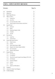
4.1 Introduction<br />
Objectives<br />
4.2 Ignition System Types<br />
4.3 Comparison between Battery and Magneto Ignition System<br />
4.4 Drawbacks (Disadvantages) of Conventional Ignition Systems<br />
4.5 Advantages of Electronic Ignition System<br />
4.6 Types of Electronic Ignition System<br />
4.7 Firing Order<br />
4.8 Importance of Ignition Timing and Ignition Advance<br />
4.9 Summary<br />
4.10 Key Words<br />
4.11 Answers to SAQs<br />
4.1 INTRODUCTION<br />
We know that in case of Internal Combustion (IC) engines, combustion of air and fuel<br />
takes place inside the engine cylinder and the products of combustion expand to produce<br />
reciprocating motion of the piston. This reciprocating motion of the piston is in turn<br />
converted into rotary motion of the crank shaft through connecting rod and crank.<br />
This rotary motion of the crank shaft is in turn used to drive the generators for generating<br />
power.<br />
We also know that there are 4-cycles of operations viz.: suction; compression; power<br />
generation and exhaust.<br />
These operations are performed either during the 2-strokes of piston or during 4-strokes<br />
of the piston and accordingly they are called as 2-stroke cycle engines and 4-stroke cycle<br />
engines.<br />
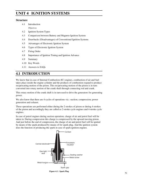
In case of petrol engines during suction operation, charge of air and petrol fuel will be<br />
taken in. During compression this charge is compressed by the upward moving piston.<br />
And just before the end of compression, the charge of air and petrol fuel will be ignited<br />
by means of the spark produced by means of for spark plug. And the ignition system<br />
does the function of producing the spark in case of spark ignition engines.<br />
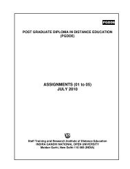
Central electrode<br />
Gas tight<br />
seal<br />
Metal tongue<br />
Contact<br />
Spark gap<br />
Figure 4.1 : Spark Plug<br />
Porceleain<br />
insulator<br />
Sealing washer<br />
Metal screw<br />
Ignition Systems<br />
51
Applied Thermal<br />
Engineering<br />
52<br />
Figure 4.1 shows atypical spark plug used with petrol engines. It mainly consists of a<br />
central electrode and metal tongue. Central electrode is covered by means of porcelain<br />
insulating material. Through the metal screw the spark plug is fitted in the cylinder head<br />
plug. When the high tension voltage of the order of 30000 volts is applied across the<br />
spark electrodes, current jumps from one electrode to another producing a spark.<br />
Whereas in case of diesel (Compression Ignition-CI) engines only air is taken in during<br />
suction operation and in compressed during compression operation and just before the<br />
end of compression, when diesel fuel is injected, it gets ignited due to heat of<br />
compression of air.<br />
Once the charge is ignited, combustion starts and products of combustion expand, i.e.<br />
they force the piston to move downwards i.e. they produce power and after producing the<br />
power the gases are exhausted during exhaust operation.<br />
Objectives<br />
After studying this unit, you should be able to<br />
• explain the different types of ignition systems,<br />
• differentiate between battery and magneto ignition system<br />
• know the drawbacks of conventional ignition system, and<br />
• appreciate the importance of ignition timing and ignition advance.<br />
4.2 <strong>IGNITION</strong> SYSTEM TYPES<br />
Basically Convectional Ignition systems are of 2 types :<br />
(a) Battery or Coil Ignition System, and<br />
(b) Magneto Ignition System.<br />
Both these conventional, ignition systems work on mutual electromagnetic induction<br />
principle.<br />
Battery ignition system was generally used in 4-wheelers, but now-a-days it is more<br />
commonly used in 2-wheelers also (i.e. Button start, 2-wheelers like Pulsar, Kinetic<br />
Honda; Honda-Activa, Scooty, Fiero, etc.). In this case 6 V or 12 V batteries will supply<br />
necessary current in the primary winding.<br />
Magneto ignition system is mainly used in 2-wheelers, kick start engines.<br />
(Example, Bajaj Scooters, Boxer, Victor, Splendor, Passion, etc.).<br />
In this case magneto will produce and supply current to the primary winding. So in<br />
magneto ignition system magneto replaces the battery.<br />
Battery or Coil Ignition System<br />
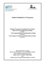
Figure 4.2 shows line diagram of battery ignition system for a 4-cylinder petrol<br />
engine. It mainly consists of a 6 or 12 volt battery, ammeter, ignition switch,<br />
auto-transformer (step up transformer), contact breaker, capacitor, distributor<br />
rotor, distributor contact points, spark plugs, etc.<br />
Note that the Figure 4.1 shows the ignition system for 4-cylinder petrol engine,<br />
here there are 4-spark plugs and contact breaker cam has 4-corners. (If it is for<br />
6-cylinder engine it will have 6-spark plugs and contact breaker cam will be a<br />
perfect hexagon).<br />
The ignition system is divided into 2-circuits :<br />
(i) Primary Circuit : It consists of 6 or 12 V battery, ammeter, ignition<br />
switch, primary winding it has 200-300 turns of 20 SWG (Sharps<br />
Wire Gauge) gauge wire, contact breaker, capacitor.
Ignition<br />
switch<br />
Ammeter<br />
(ii) Secondary Circuit : It consists of secondary winding. Secondary<br />
winding consists of about 21000 turns of 40 (S WG) gauge wire.<br />
Bottom end of which is connected to bottom end of primary and top<br />
end of secondary winding is connected to centre of distributor rotor.<br />
Distributor rotors rotate and make contacts with contact points and<br />
are connected to spark plugs which are fitted in cylinder heads<br />
(engine earth).<br />
(iii) Working : When the ignition switch is closed and engine in cranked,<br />
as soon as the contact breaker closes, a low voltage current will flow<br />
through the primary winding. It is also to be noted that the contact<br />
beaker cam opens and closes the circuit 4-times (for 4 cylinders) in<br />
one revolution. When the contact breaker opens the contact, the<br />
magnetic field begins to collapse. Because of this collapsing magnetic<br />
field, current will be induced in the secondary winding. And because<br />
of more turns (@ 21000 turns) of secondary, voltage goes unto<br />
28000-30000 volts.<br />
Battery<br />
(6 or 12V)<br />
Primary<br />
winding<br />
(200 - 300 turns of<br />
20 gauge wire)<br />
Contact<br />
Breaker<br />
Coil<br />
Contact breaker<br />
operating cam<br />
(20000 - 30000 V)<br />
Distributor<br />
contacts<br />
Secondary<br />
winding<br />
(2100 turns of<br />
40 gauge wire)<br />
Capacitor<br />
Distributor<br />
Figure 4.2 : Schematic Diagram of Coil/Battery Ignition System<br />
1<br />
2<br />
3<br />
4<br />
Spark<br />
plugs<br />
This high voltage current is brought to centre of the distributor rotor. Distributor<br />
rotor rotates and supplies this high voltage current to proper stark plug depending<br />
upon the engine firing order. When the high voltage current jumps the spark plug<br />
gap, it produces the spark and the charge is ignited-combustion starts-products of<br />
combustion expand and produce power.<br />
Note :<br />
(a) The Function of the capacitor is to reduce arcing at the contact<br />
breaker (CB) points. Also when the CB opens the magnetic field in<br />
the primary winding begins to collapse. When the magnetic field is<br />
collapsing capacitor gets fully charged and then it starts discharging<br />
and helps in building up of voltage in secondary winding.<br />
(b) Contact breaker cam and distributor rotor are mounted on the same<br />
shaft.<br />
In 2-stroke cycle engines these are motored at the same engine speed. And in<br />
4-stroke cycle engines they are motored at half the engine speed.<br />
Magneto Ignition System<br />
In this case magneto will produce and supply the required current to the primary<br />
winding. In this case as shown, we can have rotating magneto with fixed coil or<br />
rotating coil with fixed magneto for producing and supplying current to primary,<br />
remaining arrangement is same as that of a battery ignition system.<br />
Ignition Systems<br />
53
Applied Thermal<br />
Engineering<br />
54<br />
Figure 4.3 given on next page shows the line diagram of magneto ignition system.<br />
Cam<br />
Capacitor<br />
N<br />
S<br />
Contact breaker<br />
Ignition<br />
switch<br />
Distributor contact points<br />
Distributor rotor<br />
Coil<br />
Rotating magnet<br />
two pole shown<br />
1<br />
2<br />
3<br />
4<br />
Spark plugs<br />
Primary winding<br />
Figure 4.3 : Schematic Diagram of Magneto Ignition System<br />
Secondary winding<br />
4.3 COMPARISON BETWEEN BATTERY AND<br />
MAGNETO <strong>IGNITION</strong> SYSTEM<br />
Battery Ignition Magneto Ignition<br />
Battery is a must. No battery needed.<br />
Battery supplies current in primary circuit. Magneto produces the required current for<br />
primary circuit.<br />
A good spark is available at low speed<br />
also.<br />
Occupies more space. Very much compact.<br />
Recharging is a must in case battery gets<br />
discharged.<br />
Mostly employed in car and bus for which<br />
it is required to crank the engine.<br />
During starting the quality of spark is poor<br />
due to slow speed.<br />
No such arrangement required.<br />
Used on motorcycles, scooters, etc.<br />
Battery maintenance is required. No battery maintenance problems.<br />
4.4 DRAWBACKS (DISADVANTAGES) OF<br />
CONVENTIONAL <strong>IGNITION</strong> <strong>SYSTEMS</strong><br />
Following are the drawbacks of conventional ignition systems :<br />
(a) Because of arcing, pitting of contact breaker point and which will lead to<br />
regular maintenance problems.<br />
(b) Poor starting : After few thousands of kilometers of running, the timing<br />
becomes inaccurate, which results into poor starting (Starting trouble).<br />
(c) At very high engine speed, performance is poor because of inertia effects of<br />
the moving parts in the system.
(d) Some times it is not possible to produce spark properly in fouled spark<br />
plugs.<br />
In order to overcome these drawbacks Electronic Ignition system is used.<br />
4.5 ADVANTAGES OF ELECTRONIC <strong>IGNITION</strong><br />
SYSTEM<br />
Following are the advantages of electronic ignition system :<br />
(a) Moving parts are absent-so no maintenance.<br />
(b) Contact breaker points are absent-so no arcing.<br />
(c) Spark plug life increases by 50% and they can be used for about 60000 km<br />
without any problem.<br />
(d) Better combustion in combustion chamber, about 90-95% of air fuel<br />
mixture is burnt compared with 70-75% with conventional ignition system.<br />
(e) More power output.<br />
(f) More fuel efficiency.<br />
4.6 TYPES OF ELECTRONIC <strong>IGNITION</strong> SYSTEM<br />
Electronic Ignition System is as follow :<br />
(a) Capacitance Discharge Ignition system<br />
(b) Transistorized system<br />
(c) Piezo-electric Ignition system<br />
(d) The Texaco Ignition system<br />
Capacitance Discharge Ignition System<br />
It mainly consists of 6-12 V battery, ignition switch, DC to DC convertor,<br />
charging resistance, tank capacitor, Silicon Controlled Rectifier (SCR),<br />
SCR-triggering device, step up transformer, spark plugs.<br />
A 6-12 volt battery is connected to DC to DC converter i.e. power circuit through<br />
the ignition switch, which is designed to give or increase the voltage to<br />
250-350 volts. This high voltage is used to charge the tank capacitor (or<br />
condenser) to this voltage through the charging resistance. The charging resistance<br />
is also so designed that it controls the required current in the SCR.<br />
Ignition switch<br />
Battery<br />
6-12 V<br />
DC to DC<br />
convertor<br />
DC<br />
to<br />
DC<br />
(Charging resistance)<br />
R<br />
250 V 350 V<br />
Tank<br />
capacitor C<br />
or condenser<br />
SCR<br />
SCR<br />
triggering<br />
device<br />
Figure 4.4 : Capacitance Discharge Ignition System<br />
To<br />
spark plug<br />
P B<br />
Ignition Systems<br />
55
Applied Thermal<br />
Engineering<br />
56<br />
Depending upon the engine firing order, whenever the SCR triggering device,<br />
sends a pulse, then the current flowing through the primary winding is stopped.<br />
And the magnetic field begins to collapse. This collapsing magnetic field will<br />
induce or step up high voltage current in the secondary, which while jumping the<br />
spark plug gap produces the spark, and the charge of air fuel mixture is ignited.<br />
Transistorized Assisted Contact (TAC) Ignition System<br />
Figure 4.5 shows the TAC system.<br />
Advantages<br />
(a) The low breaker-current ensures longer life.<br />
(b) The smaller gap and lighter point assembly increase dwell time<br />
minimize contact bouncing and improve repeatability of secondary<br />
voltage.<br />
(c) The low primary inductance reduces primary inductance reduces<br />
primary current drop-off at high speeds.<br />
Disadvantages<br />
(a) As in the conventional system, mechanical breaker points are<br />
necessary for timing the spark.<br />
(b) The cost of the ignition system is increased.<br />
(c) The voltage rise-time at the spark plug is about the same as before.<br />
Ignition<br />
switch<br />
Battery<br />
S<br />
P<br />
A<br />
Ballast resistor<br />
E - Emitter<br />
High voltage to distributor<br />
Figure 4.5 : Transistorized Assisted Contact (TAC) Ignition System<br />
Piezo-electric Ignition System<br />
Cam<br />
Contact<br />
breaker<br />
The development of synthetic piezo-electric materials producing about 22 kV by<br />
mechanical loading of a small crystal resulted in some ignition systems for single<br />
cylinder engines. But due to difficulties of high mechanical loading need of the<br />
order of 500 kg timely control and ability to produce sufficient voltage, these<br />
systems have not been able to come up.<br />
The Texaco Ignition System<br />
Due to the increased emphasis on exhaust emission control, there has been a<br />
sudden interest in exhaust gas recirculation systems and lean fuel-air mixtures.<br />
To avoid the problems of burning of lean mixtures, the Texaco Ignition system has<br />
been developed. It provides a spark of controlled duration which means that the<br />
spark duration in crank angle degrees can be made constant at all engine speeds.<br />
It is a AC system. This system consists of three basic units, a power unit, a control<br />
unit and a distributor sensor.<br />
This system can give stable ignition up to A/F ratios as high as 24 : 1.
4.7 FIRING ORDER<br />
• The order or sequence in which the firing takes place, in different cylinders of a<br />
multicylinder engine is called Firing Order.<br />
• In case of SI engines the distributor connects the spark plugs of different cylinders<br />
according to Engine Firing Order.<br />
Advantages<br />
(a) A proper firing order reduces engine vibrations.<br />
(b) Maintains engine balancing.<br />
(c) Secures an even flow of power.<br />
• Firing order differs from engine-to-engine.<br />
• Probable firing orders for different engines are :<br />
− 3 cylinder = 1-3-2<br />
− 4 cylinder engine (inline) = 1-3-4-2<br />
1-2-4-3<br />
− 4 cylinder horizontal opposed engine = 1-4-3-2<br />
(Volkswagen engine)<br />
− 6-cylinder in line engine = 1-5-3-6-2-4<br />
(Cranks in 3 pairs) 1-4-2-6-3-5<br />
1-3-2-6-4-5<br />
1-2-4-6-5-3<br />
− 8 cylinder in line engine 1-6-2-5-8-3-7-4<br />
1-4-7-3-8-5-2-6<br />
8 cylinder V type 1-5-4-8-6-3-7-2<br />
1-5-4-2-6-3-7-8<br />
1-6-2-5-8-3-7-4<br />
1-8-4-3-6-5-7-2<br />
Cylinder 1 is taken from front of inline and front right side in<br />
V engines.<br />
4.8 IMPORTANCE OF <strong>IGNITION</strong> TIMING AND<br />
<strong>IGNITION</strong> ADVANCE<br />
Ignition timing is very important, since the charge is to be ignited just before (few<br />
degrees before TDC) the end of compression, since when the charge is ignited, it will<br />
take some time to come to the required rate of burning.<br />
Ignition Advance<br />
The purpose of spark advance mechanism is to assure that under every condition<br />
of engine operation, ignition takes place at the most favorable instant in time i.e.<br />
most favorable from a standpoint of engine power, fuel economy and minimum<br />
exhaust dilution. By means of these mechanisms the advance angle is accurately<br />
set so that ignition occurs before TDC point of the piston. The engine speed and<br />
the engine load are the control quantities required for the automatic adjustment of<br />
the ignition timing. Most of the engines are fitted with mechanisms which are<br />
integral with the distributor and automatically regulate the optimum spark advance<br />
to account for change of speed and load. The two mechanisms used are :<br />
(a) Centrifugal advance mechanism, and<br />
Ignition Systems<br />
57
Applied Thermal<br />
Engineering<br />
58<br />
(b) Vacuum advance mechanism.<br />
Centrifugal Advance Mechanism<br />
The centrifugal advance mechanism controls the ignition timing for full- load<br />
operation. The adjustment mechanism is designed so that its operation results in<br />
the desired advance of the spark. The cam is mounted, movably, on the distributor<br />
shaft so that as the speed increases, the flyweights which are swung farther and<br />
farther outward, shaft the cam in the direction of shaft rotation. As a result, the<br />
cam lobes make contact with the breaker lever rubbing block somewhat earlier,<br />
thus shifting the ignition point in the early or advance direction. Depending on the<br />
speed of the engine, and therefore of the shaft, the weights are swung outward a<br />
greater or a lesser distance from the center. They are then held in the extended<br />
position, in a state of equilibrium corresponding to the shifted timing angle, by a<br />
retaining spring which exactly balances the centrifugal force. The weights shift the<br />
cam either or a rolling contact or sliding contact basis; for this reasons we<br />
distinguish between the rolling contact type and the sliding contact type of<br />
centrifugal advance mechanism.<br />
The beginning of the timing adjustment in the range of low engine speeds and the<br />
continues adjustment based on the full load curve are determined by the size of the<br />
weights by the shape of the contact mechanisms (rolling or sliding contact type),<br />
and by the retaining springs, all of which can be widely differing designs. The<br />
centrifugal force controlled cam is fitted with a lower limit stop for purposes of<br />
setting the beginning of the adjustment, and also with an upper limit stop to<br />
restrict the greatest possible full load adjustment. A typical sliding contact type<br />
centrifugal advance mechanism is shown in Figures 4.6(a) and (b).<br />
Weight return spring<br />
(a) (b)<br />
Figure 4.6 : Sliding Contact Type Centrifugal Advance Mechanism<br />
Vacuum Advance Mechanism<br />
Yoke<br />
Cam<br />
Support plate<br />
Vacuum advance mechanism shifts the ignition point under partial load operation.<br />
The adjustment system is designed so that its operation results in the prescribed<br />
partial load advance curve. In this mechanism the adjustment control quantity is<br />
the static vacuum prevailing in the carburetor, a pressure which depends on the<br />
position of the throttle valve at any given time and which is at a maximum when<br />
this valve is about half open. This explains the vacuum maximum.<br />
The diaphragm of a vacuum unit is moved by changes in gas pressure. The<br />
position of this diaphragm is determined by the pressure differential at any given<br />
moment between the prevailing vacuum and atmospheric pressure. The beginning<br />
of adjustment is set by the pre-established tension on a compression spring. The<br />
diaphragm area, the spring force, and the spring rigidity are all selected in<br />
accordance with the partial –load advance curve which is to be followed and are<br />
all balanced with respect to each other. The diaphragm movement is transmitted<br />
through a vacuum advance arm connected to the movable breaker plate, and this
SAQ 1<br />
movement shifts the breaker plate an additional amount under partial load<br />
condition in a direction opposite to the direction of rotation of the distributor<br />
shaft. Limit stops on the vacuum advance arm in the base of the vacuum unit<br />
restrict the range of adjustment.<br />
The vacuum advance mechanism operates independent of the centrifugal advance<br />
mechanism. The mechanical interplay between the two advance mechanisms,<br />
however, permits the total adjustment angle at any given time to be the result of<br />
the addition of the shifts provided by the two individual mechanisms operates in<br />
conjunction with the engine is operating under partial load. A typical vacuum<br />
advance mechanism is shown in Figure 4.7.<br />
Figure 4.7 : Vacuum Advance Mechanism<br />
(a) What do you understand by ‘ignition’? How is it related to ‘combustion’?<br />
(b) What are the requirements of an ignition system for an IC engines?<br />
(c) Differentiate between battery and magneto ignition system.<br />
(d) Explain in brief the drawbacks of conventional ignition system.<br />
(e) What is the difference between ‘ignition timing’ and ‘firing order’?<br />
(f) List the various electronic ignition system in use.<br />
4.9 SUMMARY<br />
Vacuum advance arm<br />
Movable breaker plate<br />
Vacuum unit<br />
Diaphragm<br />
Compression<br />
Hose connection<br />
In SI engines, the combustion process is initiated by a spark between the two electrodes<br />
of spark plug. This occurs just before the end of compression stroke. Ignition is only a<br />
pre-requisite of combustion. In this unit, we have learnt in detail the different types of<br />
ignition systems. The difference between battery and magneto ignition systems lies only<br />
in the source of electrical energy. Battery ignition system uses a battery, magneto<br />
ignition system uses a magneto to supply low voltages all other system components<br />
being similar.<br />
The order or sequence in which the firing takes place, in different cylinders of a<br />
multi-cylinder engine is called firing order.<br />
Ignition Systems<br />
59
Applied Thermal<br />
Engineering<br />
60<br />
4.10 KEY WORDS<br />
Battery Ignition System : It is commonly used because of its combined<br />
cheapness, convenience of maintenance, attention<br />
and general suitability.<br />
Magneto Ignition System : It is an efficient, reliable, self contained unit,<br />
which is often preferred for air craft engines<br />
because storage batteries are heavy and<br />
troublesome.<br />
Firing Order : It is the order in which various cylinders of a<br />
multi-cylinder engine fire.<br />
Ignition Timing : It is the correct instant for the introduction of<br />
spark near the end of compression stroke in the<br />
cycle.<br />
4.11 ANSWERS TO SAQs<br />
Refer the preceding text for all the Answers to SAQs.