Tunnel and shaft solutions brochure - Humes
Tunnel and shaft solutions brochure - Humes
Tunnel and shaft solutions brochure - Humes

Create successful ePaper yourself
Turn your PDF publications into a flip-book with our unique Google optimized e-Paper software.
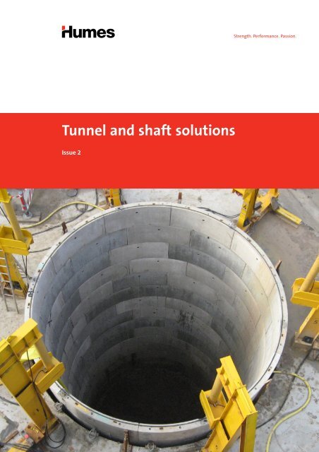
<strong>Tunnel</strong> <strong>and</strong> <strong>shaft</strong> <strong>solutions</strong><br />
Issue 2
Contents<br />
Segmental tunnel linings 3<br />
Applications 3<br />
Product range 3<br />
Features <strong>and</strong> benefits 3<br />
Joint <strong>and</strong> connection details 4<br />
Circle joints 4<br />
Cross joints 5<br />
Innovative features 6<br />
Caulking grooves <strong>and</strong> sealing grooves 6<br />
Grout socket assembly 6<br />
Packings 6<br />
Special rings 6<br />
<strong>Tunnel</strong> construction methods 6<br />
Segmental <strong>and</strong> one piece <strong>shaft</strong>s 7<br />
Applications 7<br />
Features <strong>and</strong> benefits 8<br />
Cost savings 8<br />
Safer work environment 8<br />
Minimal environmental impact 8<br />
Innovative design 8<br />
Product range 8<br />
Construction methods 9<br />
Caisson method 9<br />
Underpin method 10<br />
Combination of the caisson <strong>and</strong><br />
underpin methods<br />
11<br />
Typical ring configuration 12<br />
One piece <strong>shaft</strong>s 12<br />
Segmental <strong>shaft</strong>s 14<br />
3-pin precast arches 19<br />
Applications 19<br />
Features <strong>and</strong> benefits 19<br />
Product range 20<br />
Arch system components 21<br />
Box culverts 22<br />
Applications 22<br />
Features <strong>and</strong> benefits 22<br />
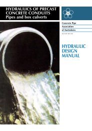
Jacking pipes 23<br />
The jacking technique (microtunnelling) 23<br />
Benefits of pipe jacking 24<br />
Technical 24<br />
Safety 24<br />
Economic 24<br />
Environmental 24<br />
Steel reinforced concrete pipes (SRCP) 25<br />
Benefits of reinforced concrete jacking pipes 25<br />
Fixed steel collar pipes 26<br />
Loose steel collar pipes 31<br />
Selection of jacking pipes 32<br />
Vitrified clay pipes 35<br />
Features <strong>and</strong> benefits 35<br />
Product range 37<br />
Connection to st<strong>and</strong>ard pipes <strong>and</strong><br />
access chambers<br />
40<br />
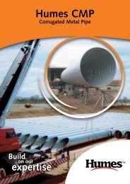
Corrugated Metal Pipe (CMP) 42<br />
Applications 42<br />
Features <strong>and</strong> benefits 42<br />
Backfilling 43<br />
Precast <strong>solutions</strong> 44<br />
Contact information 45
2 <strong>Tunnel</strong> <strong>and</strong> <strong>shaft</strong> <strong>solutions</strong>
Segmental tunnel linings<br />
<strong>Humes</strong>’ trapezoidal segments use the latest technology<br />
to deliver a smooth bore, single pass tunnel, which can<br />
withst<strong>and</strong> the increasing dem<strong>and</strong>s of modern tunnel<br />
boring machines <strong>and</strong> poor ground conditions.<br />
Applications<br />
• Utility tunnels<br />
• Traffic tunnels (road <strong>and</strong> rail)<br />
• Water pipelines<br />
• Desalination structures<br />
• Escape tunnels<br />
Product range<br />
<strong>Humes</strong> produces segmental linings measuring<br />
2 m to 5.3 m (internal) diameter. Other sizes may be<br />
produced on request (refer to Table 1 below).<br />
Table 1 – Segmental tunnel linings details<br />
Internal<br />
diameter<br />
(m)<br />
External<br />
diameter<br />
(m)<br />
Maximum<br />
segment width<br />
(mm)<br />
Minimum<br />
segment width<br />
(mm)<br />
Weight per<br />
segment<br />
(kg)<br />
Ring<br />
weight<br />
(tonnes)<br />
Bolts per ring<br />
No. x dia. x length<br />
(mm)<br />
2.07 2.43 1,010 990 520 3.10 12 x M16 x 295<br />
2.44 2.80 1,007 993 600 3.60 12 x M16 x 355<br />
2.85 3.21 1,007.5 992.5 700 4.19 12 x M16 x 365<br />
2.90 3.26 1,005 995 710 4.27 12 x M16 x 365<br />
3.00 3.35 1,210.5 1,189.5 856 5.13 12 x M16 x 365<br />
3.35 3.71 1,010 1,000 820 4.89 12 x M16 x 400<br />
3.38 3.84 1,083 1,051 1,200 6.80 12 x M20 x 490<br />
3.84 4.24 1,015 985 1,040 6.20 12 x M20 x 410<br />
5.30 5.80 1,522 1,478 2,090 16.67 12 x M20 x 440<br />
Note:<br />
These specifications <strong>and</strong> details may change, please contact <strong>Humes</strong> for confirmation.<br />
Features <strong>and</strong> benefits<br />
<strong>Humes</strong> offer segmental tunnel linings in partnership with Buchan Concrete Solutions Limited (UK).<br />
• Cost effective installation.<br />
- Non-ferrous self locking, self-aligning connectors<br />
reduce internal bolt recesses.<br />
- Segments are provided with a fast coarse thread<br />
plastic grout socket assembly at the centroid for<br />
lifting <strong>and</strong> grouting.<br />
- Segments are designed to be machine h<strong>and</strong>led with<br />
a rotating arm erector.<br />
• Three segment types for curved or straight<br />
construction. Curved alignments are easily<br />
accommodated by altering the ring orientation (refer<br />
to Figure 6 on page 6).<br />
• Single pass finish for permanent structures.<br />
• The elimination of cruciform joints.<br />
• The trapezoidal joint arrangement assists with a good<br />
ring build <strong>and</strong> helps maintain the ring shape prior<br />
to grouting.<br />
<strong>Tunnel</strong> <strong>and</strong> <strong>shaft</strong> <strong>solutions</strong> 3<br />
<strong>Tunnel</strong> <strong>and</strong> <strong>shaft</strong> <strong>solutions</strong>
Joint <strong>and</strong> connection details<br />
Circle joints<br />
A self-locking plastic connector provides a robust joint<br />
fixing for tunnel linings.<br />
The connector is manufactured from a high strength<br />
durable plastic. It combines the advantages of a bolted<br />
connection with the speed, economy <strong>and</strong> alignment<br />
characteristics of a dowel.<br />
The system has been developed in conjunction with<br />
major tunnelling contractors <strong>and</strong> is suitable for use in<br />
traditional open face shields or with the latest full face<br />
tunnel boring machines.<br />
The self-locking connector offers many benefits:<br />
• The dowels allow a very fast ring erection sequence.<br />
• They are designed to reduce lipping between segments.<br />
Figure 1 – Circle joint detail<br />
4 <strong>Tunnel</strong> <strong>and</strong> <strong>shaft</strong> <strong>solutions</strong><br />
High strength dowel<br />
giving self alignment <strong>and</strong><br />
good shear connection<br />
• The system is tolerant of a dirty environment <strong>and</strong><br />
allows for the initial misalignment of segments to<br />
compensate for tapered joints <strong>and</strong> gaskets.<br />
• Highly durable connection with no corrodible parts.<br />
• The rigid dowel action of the coupler re-aligns the<br />
segment <strong>and</strong> minimises the stepping of joints.<br />
• Self-locking <strong>and</strong> self-aligning.<br />
• No circle joint pockets to fill, thus reducing<br />
finishing time.<br />
• Suitable for use with all types of sealing systems,<br />
including Ethylene Propylene Diene Monomer (EPDM)<br />
compression gaskets <strong>and</strong> hydrophilic seals.<br />
• Does not induce bursting forces in the concrete.<br />
• Fully compatible with elastic compression gasket. The<br />
elastic performance of the connection compliments<br />
the behaviour of the gasket, which means that it can<br />
be used with a stiff gasket <strong>and</strong> copes with varying<br />
joint gap.<br />
Movable plastic<br />
anchors allow segment<br />
to be located when<br />
imperfectly aligned<br />
Threaded screw<br />
connection which<br />
allows a push fit<br />
Shield ram thrust
Figure 2 – Circle joint connector interaction<br />
Load (KN)<br />
25<br />
22.5<br />
20<br />
17.5<br />
15<br />
12.5<br />
10<br />
7.5<br />
Elevation on ring<br />
5<br />
2.5<br />
Cross joints<br />
1 No Plastic grout/Lifting socket<br />
External diameter<br />
Internal diameter<br />
Water pressure<br />
Cross joint connections are made by passing a curved<br />
M16 threaded bolt through a pocket in each segment.<br />
The bolts are made for grade 8.8 steel <strong>and</strong> have a<br />
nominal ultimate tensile strength (UTS) of 800 N/mm2 (or Mpa) <strong>and</strong> a nominal yield strength of 640 N/mm2 (or Mpa). The segments are cast with bolt hole recesses<br />
designed to accommodate gel impregnated grommets.<br />
All raw materials comply with current Australian<br />
st<strong>and</strong>ards. Manufacturing is carried out in<br />
accordance with the requirements of our quality<br />
management system.<br />
Gasket compression<br />
30o 60o 1000 (Nominal)<br />
30 o<br />
30 o<br />
60 o 15 o<br />
Stiff EPDM gasket compression characteristic<br />
0<br />
0 0.5 1 1.5 2 2.5 3 3.5 4 4.5 5<br />
A resultant joint gap of 1.5 mm @ equilibrium.<br />
Gasket sealing performance remains unaffected.<br />
Joint gap (mm)<br />
Joint gap<br />
Self-locking plastic connector extension characteristic<br />
Self-locking<br />
plastic<br />
connector<br />
extension<br />
Figure 3 – Cross joint detail<br />
Sealing groove<br />
Inner face of typical segment Typical cross joint detail<br />
Bituminous packing<br />
to all longitudinal joints<br />
Caulking groove<br />
Figure 4 – Curved bolts used for cross joints<br />
Buclock connectors<br />
Typical circle joint detail<br />
12 no. equally spaced<br />
Radiused bolt<br />
Sealing groove Curved bolt<br />
Caulking groove<br />
<strong>Tunnel</strong> <strong>and</strong> <strong>shaft</strong> <strong>solutions</strong> 5<br />
<strong>Tunnel</strong> <strong>and</strong> <strong>shaft</strong> <strong>solutions</strong>
Right:<br />
Attaching a grout<br />
plug to a grout/<br />
lifting socket<br />
Innovative features<br />
Caulking grooves <strong>and</strong> sealing grooves<br />
All segments are cast with caulking grooves on the<br />
circumferential <strong>and</strong> longitudinal sides. Sealing grooves<br />
for either hydrophilic strip or elastomeric compression<br />
gaskets can be incorporated at the time of casting.<br />
Grout socket assembly<br />
Each segment is fitted with a plastic grout socket<br />
assembly which includes a non-return valve. The socket is<br />
used to inject grout to permanently secure the rings.<br />
Packings<br />
Bituminous felt packing of 3 mm nominal thickness<br />
should be used on all longitudinal joints <strong>and</strong> can be<br />
supplied if required. Circumferential packings made from<br />
3 mm bituminous felt or 3 mm or 6 mm timber can also<br />
be supplied if required.<br />
Special rings<br />
The rings currently available have a taper across one<br />
axis. Non st<strong>and</strong>ard tapers can be manufactured to the<br />
purchaser’s specific requirements.<br />
<strong>Tunnel</strong> construction methods<br />
The rings consist of three different segment types.<br />
Segments are supplied to the erector in a predetermined<br />
sequence dependant upon the alignment required.<br />
The ring orientation is altered by erecting segments in a<br />
different order (refer to Figure 6).<br />
6 <strong>Tunnel</strong> <strong>and</strong> <strong>shaft</strong> <strong>solutions</strong><br />
Rings in same orientation<br />
for curved alignment<br />
Figure 5 – Grout socket assembly<br />
Grout/Lifting socket<br />
Non-return valve<br />
Figure 6 – Segment orientation for curved <strong>and</strong><br />
straight alignments<br />
Rings in same orientation<br />
for curved alignment<br />
Rings in same orientation<br />
for curved alignment<br />
Rings rotated at 120o Rings rotated at 120° for<br />
straight alignment<br />
for straight alignment<br />
Sealing washer<br />
Threaded<br />
grout<br />
plug
Segmental <strong>and</strong> one piece <strong>shaft</strong>s<br />
Applications<br />
<strong>Humes</strong>’ precast concrete <strong>shaft</strong>s are an economical<br />
<strong>and</strong> safe solution for permanent <strong>and</strong> temporary<br />
underground structures. They are ideal for a variety of<br />
applications including:<br />
• ventilation <strong>shaft</strong>s<br />
• escape <strong>shaft</strong>s<br />
• launch <strong>and</strong> receival <strong>shaft</strong>s for pipe jacking applications<br />
• storage overflow <strong>and</strong> pump stations (sewerage)<br />
• water harvesting <strong>and</strong> reuse.<br />
The <strong>shaft</strong> system suits a variety of soil conditions, <strong>and</strong><br />
provides a soil <strong>and</strong> watertight solution.<br />
<strong>Humes</strong> offer segmental <strong>shaft</strong>s in partnership with Buchan Concrete<br />
Solutions Limited (UK).<br />
<strong>Tunnel</strong> <strong>and</strong> <strong>shaft</strong> <strong>solutions</strong> 7<br />
<strong>Tunnel</strong> <strong>and</strong> <strong>shaft</strong> <strong>solutions</strong>
Features <strong>and</strong> benefits<br />
Precast <strong>shaft</strong>s provide installation contractors with a<br />
number of significant benefits over traditional <strong>shaft</strong><br />
construction methods; greater installation efficiencies,<br />
cost benefits, <strong>and</strong> a safer work environment. <strong>Humes</strong>’<br />
precast <strong>shaft</strong>s also help to reduce the environmental<br />
impact of construction.<br />
Cost savings<br />
• Installation time is significantly reduced as excavation<br />
<strong>and</strong> ring placement can be on a continuous cycle.<br />
• The precast concrete segments provide a one-pass<br />
finished <strong>shaft</strong>, so no further concrete work is required<br />
to finish the structure.<br />
• There is no requirement for specialist labour <strong>and</strong> a<br />
small team should be capable of managing the entire<br />
installation process.<br />
Safer work environment<br />
<strong>Humes</strong>’ precast <strong>shaft</strong>s enable contractors to provide a<br />
safer environment for their workers:<br />
• The majority of work can be carried out above ground<br />
(caisson method).<br />
• Overhead services hazards are minimised as no large<br />
cranes are required.<br />
• The system has a built-in safety barrier created by the<br />
installation of the top ring.<br />
Minimal environmental impact<br />
An efficient design means <strong>shaft</strong>s have minimal impact<br />
on project sites <strong>and</strong> the surrounding environment:<br />
• Noise <strong>and</strong> ground vibration are virtually eliminated as<br />
no hammering is required.<br />
• The excavation <strong>and</strong> site storage areas are minimal, as<br />
the precast units are relatively compact at less than<br />
2.5 m wide.<br />
• Shaft installation does not require the use of water or<br />
wet concrete (except for the base <strong>and</strong> collar).<br />
8 <strong>Tunnel</strong> <strong>and</strong> <strong>shaft</strong> <strong>solutions</strong><br />
Innovative design<br />
• The <strong>shaft</strong> can be installed accurately due to the<br />
high degree of control over the rate <strong>and</strong> direction<br />
of installation.<br />
• No bracing is required due to its structurally efficient<br />
circular shape. The <strong>shaft</strong> gains structural stability from<br />
the surrounding soil so tie-backs or ring-beams are not<br />
required to support the segments.<br />
• Suited to a variety of soil conditions.<br />
• Extensive diameter range with full range of<br />
ancillary products.<br />
• A soil <strong>and</strong> watertight solution.<br />
• A unique external fixing is used to join the segments,<br />
eliminating the need for specialist trades, like welders,<br />
on site.<br />
Product range<br />
<strong>Humes</strong> is proud to announce the expansion of our range<br />
of precast concrete <strong>shaft</strong>s; we now offer the following<br />
sizes in one piece <strong>and</strong> segmental <strong>shaft</strong>s:<br />
• 2.4 m one piece <strong>shaft</strong><br />
• 3 m one piece <strong>shaft</strong><br />
• 3.6 m one piece <strong>shaft</strong><br />
• 4.5 m segmental <strong>shaft</strong><br />
• 6 m segmental <strong>shaft</strong><br />
• 7.5 m segmental <strong>shaft</strong><br />
• 9 m segmental <strong>shaft</strong><br />
• 10.5 m segmental <strong>shaft</strong><br />
• 12.5 m segmental <strong>shaft</strong><br />
• 15 m segmental <strong>shaft</strong><br />
• Sizes up to 25 m are also available, please contact<br />
<strong>Humes</strong> for availability.
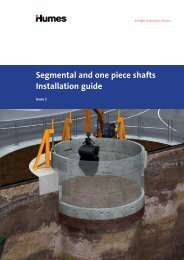
Construction methods<br />
There are three techniques available to install a precast<br />
concrete segmental <strong>shaft</strong>. These are the caisson method,<br />
underpin method <strong>and</strong> the last method is a combination<br />
of the two. The design of caisson <strong>and</strong> underpin <strong>shaft</strong>s<br />
requires specialist skills <strong>and</strong> should be executed by a<br />
designer experienced with these construction methods.<br />
Caisson method<br />
The caisson method is generally used in softer soils with<br />
or without the presence of ground water. Caisson are<br />
either installed as a ‘wet caisson’ where the water level<br />
inside the caisson is slightly higher than the external<br />
ground water level, or as a ‘dry caisson’ where the inside<br />
of the caisson is open to the atmosphere. In the caisson<br />
method, the precast concrete elements are erected at<br />
the surface <strong>and</strong> are then lowered into the ground whilst<br />
excavation progresses.<br />
There are a number of common features unique<br />
to <strong>Humes</strong>' caisson <strong>shaft</strong> systems which facilitate<br />
installation. These are:<br />
• In-situ cast concrete collars<br />
These collars act as a guide ring to keep the caisson<br />
<strong>shaft</strong> vertical <strong>and</strong>, in larger diameter <strong>shaft</strong>s, resist the<br />
force from the hydraulic jacks.<br />
• Hydraulic jacks (gallows)<br />
These are installed to both steer the <strong>shaft</strong> <strong>and</strong> to add<br />
to the vertical force in addition to the self weight<br />
of the <strong>shaft</strong> lining (generally not required for one<br />
piece rings).<br />
• Excavation should be slightly larger in diameter than<br />
the precast concrete <strong>shaft</strong><br />
The annulus between the <strong>shaft</strong> <strong>and</strong> the excavated<br />
ground should be filled with suitable fluid (usually<br />
bentonite with additives as required to suit the ground<br />
conditions) which acts both as a lubricant but also<br />
supports the ground during installation.<br />
• The bottom/choker ring is wider than the st<strong>and</strong>ard<br />
ring <strong>and</strong> the same diameter as the excavation<br />
The choker ring is designed to provide a seal diameter<br />
between the <strong>shaft</strong> <strong>and</strong> excavated ground so that the<br />
fluid in the annulus above the ring is retained. The<br />
choker segments are also designed to bolt the steel<br />
cutting edge to the <strong>shaft</strong> <strong>and</strong> connect the underpin<br />
segment. Refer to combination method on page 11.<br />
• A steel cutting edge underneath the<br />
bottom/choker ring<br />
The steel cutting edge literally cuts through the<br />
ground. An additional function is that it acts<br />
as a stiffener.<br />
• All caisson units are provided with grout sockets<br />
This allows the exterior annulus to be filled with a<br />
cementitious grout at completion of the installation.<br />
<strong>Tunnel</strong> <strong>and</strong> <strong>shaft</strong> <strong>solutions</strong> 9<br />
Top:<br />
Caisson method of<br />
<strong>shaft</strong> installation<br />
showing hydraulic<br />
jacks (gallows)<br />
Bottom:<br />
Bottom/choker<br />
ring with steel<br />
cutting edge<br />
<strong>Tunnel</strong> <strong>and</strong> <strong>shaft</strong> <strong>solutions</strong>
Top:<br />
Underpin method<br />
of <strong>shaft</strong> installation<br />
Bottom:<br />
Segment lifting<br />
frame for underpin<br />
method<br />
Underpin method<br />
The underpin method can be used in self supported soil<br />
where caisson installation is not possible. In this method,<br />
the precast concrete elements are progressively installed<br />
at the base of the excavation. Segmental rings are built<br />
<strong>and</strong> the annulus between their outside perimeter <strong>and</strong><br />
the excavated ground is immediately grouted.<br />
The recommended installation procedure is as follows:<br />
• Secure the first installed ring by casting a concrete<br />
collar around it prior to excavating underneath<br />
to construct the next ring. Shear connection may<br />
be required.<br />
• Always excavate, install <strong>and</strong> grout one ring at a time.<br />
This reduces the risk of overloading the upper rings<br />
which could pull down the whole ring build, due to<br />
lack of ground friction.<br />
• Excavation of the next ring below can commence once<br />
the grout reaches it recommended strength.<br />
• The underpin segments are designed to be installed<br />
using a specialised h<strong>and</strong>ling/lifting frame. The<br />
segment will be secured into the frame via the plastic<br />
grout socket assembly. If you wish to hire a frame,<br />
contact <strong>Humes</strong> for assistance.<br />
10 <strong>Tunnel</strong> <strong>and</strong> <strong>shaft</strong> <strong>solutions</strong>
Combination of the caisson <strong>and</strong><br />
underpin methods<br />
A combination of both methods can be used if the<br />
soil condition varies. Installation commences with<br />
the caisson method (using a special choker ring) <strong>and</strong><br />
then shifts to the underpin method when the hard<br />
soil ground is reached.<br />
A special choker/transition ring must be used to enable<br />
the shift to the underpin construction method. The<br />
choker/transition rings are wider than the st<strong>and</strong>ard<br />
caisson rings allowing the connection of underpin rings<br />
below this ring as required.<br />
With some ground conditions it may be necessary or<br />
cost effective to stop the caisson at a certain depth.<br />
After grouting the exterior annulus, it may be possible<br />
to remove the cutting edge <strong>and</strong> then continue the <strong>shaft</strong><br />
construction using the underpin method.<br />
Figure 7 – Combination method details<br />
Caisson rings<br />
Choker ring<br />
Underpin rings<br />
Tie rod<br />
Double eye bolt<br />
<strong>Tunnel</strong> <strong>and</strong> <strong>shaft</strong> <strong>solutions</strong> 11<br />
Right:<br />
Combination<br />
method of <strong>shaft</strong><br />
installation<br />
<strong>Tunnel</strong> <strong>and</strong> <strong>shaft</strong> <strong>solutions</strong>
Typical ring configuration<br />
One piece <strong>shaft</strong>s<br />
One piece caisson units are ideally suited for construction<br />
of sewage pump station wet wells, access chambers for<br />
large diameter pipelines <strong>and</strong> jacking launch or receival<br />
<strong>shaft</strong>s for small diameter microtunnelling. One piece<br />
<strong>shaft</strong>s can be supplied in a range of diameters but<br />
st<strong>and</strong>ard sizes are as detailed in Table 2 below.<br />
Table 2 – St<strong>and</strong>ard one piece caisson units*<br />
Nominal<br />
diameter<br />
(DN)<br />
Internal<br />
diameter<br />
(mm)<br />
External<br />
diameter<br />
(mm)<br />
Height of<br />
st<strong>and</strong>ard units<br />
(mm)*<br />
Mass of st<strong>and</strong>ard<br />
units<br />
(tonnes)<br />
Number of tie<br />
rod couplers<br />
2,400 2,374 2,782 1,000 4.3 6<br />
3,000 3,060 3,460 1,000 5.2 8<br />
3,600 3,600 4,000 1,000 6.0 9<br />
Note:<br />
* Dimensions are subject to change. Contact <strong>Humes</strong> for confirmation.<br />
Figure 8 – One piece <strong>shaft</strong> used in a pump station application<br />
Vertical tie rod<br />
12 <strong>Tunnel</strong> <strong>and</strong> <strong>shaft</strong> <strong>solutions</strong><br />
Cutting edge<br />
Detail – Panelled ring with recesses
Joint <strong>and</strong> connection details<br />
Horizontal joints between one piece caisson units are<br />
sealed with both a hydrophilic rubber seal near the<br />
external surface <strong>and</strong> a butyl mastic rubber seal near the<br />
internal surface. For temporary installations, a single<br />
butyl mastic seal is likely to be sufficient. In addition,<br />
units come complete with a groove on the inside face<br />
which allows caulking of the internal surface.<br />
Horizontal joints between one piece caisson rings are<br />
connected with vertical tie rods that are mainly provided<br />
for temporary loads during installation. These rods are<br />
normally made from galvanised steel. For permanent<br />
installations, it is recommended that approximately half<br />
of these rods <strong>and</strong> couplers be replaced with stainless<br />
steel so that the hydrophilic seal is confined during the<br />
life of the structure.<br />
Special units<br />
Special units include the following:<br />
• Panelled rings which include recesses, are designed<br />
to provide a shear connection between the precast<br />
concrete <strong>shaft</strong> <strong>and</strong> an in-situ cast concrete plug,<br />
installed to prevent flotation. Either single or multiple<br />
panelled rings are particularly effective for wet<br />
caissons where the connection plug will be cast prior<br />
to de-watering.<br />
• Rings with corrosion protection linings (either High<br />
Density Polyethylene (HDPE) or Plastiline® - Polyvinyl<br />
Chloride (PVC)) for added corrosion resistance.<br />
• Soft eye rings are applied to small diameter<br />
(DN600 or less) microtunnelling applications. Rings<br />
can be provided with either reduced or no steel<br />
reinforcement at pipe penetrations.<br />
• Cover slabs incorporating openings <strong>and</strong>/or lids as<br />
required. The joint <strong>and</strong> connection details for the<br />
st<strong>and</strong>ard rings are included with these cover slabs.<br />
<strong>Tunnel</strong> <strong>and</strong> <strong>shaft</strong> <strong>solutions</strong> 13<br />
Left:<br />
One piece <strong>shaft</strong><br />
Right:<br />
Cover slab<br />
<strong>Tunnel</strong> <strong>and</strong> <strong>shaft</strong> <strong>solutions</strong>
Segmental <strong>shaft</strong>s<br />
Where <strong>shaft</strong> diameters exceed the size of the one piece<br />
ring '3.60 m ID', the segmental <strong>shaft</strong> system comes<br />
into its own so that <strong>shaft</strong>s of almost any diameter<br />
can be constructed.<br />
A ring consists of a series of ordinary segments which<br />
have four edges that are perpendicular to each other<br />
<strong>and</strong> two tapered segments (left <strong>and</strong> right) which have<br />
one tapered end which allows for closing of the ring<br />
by simply lowering the last (tapered right) segment<br />
into position.<br />
Number of segments per ring varies depending on the<br />
<strong>shaft</strong> diameter (refer to Table 3 below).<br />
Table 3 – St<strong>and</strong>ard segmental <strong>shaft</strong> details<br />
Internal<br />
diameter<br />
(m)<br />
External<br />
diameter<br />
(m)<br />
Height<br />
(m)<br />
Segments per ring<br />
Ordinary Tapered<br />
Mass per ring<br />
(tonnes)<br />
Mass per<br />
segment<br />
(kg)<br />
4.50 4.90 1.00 5 2 7.36 1,050<br />
6.00 6.45 1.00 7 2 10.78 1,200<br />
7.50 7.95 1.00 8 2 13.37 1,340<br />
9.00 9.50 1.00 12 2 17.80 1,270<br />
10.50 11.00 1.00 12 2 25.40 1,820<br />
12.50 13.15 1.00 14 2 32.80 2,050<br />
15.00 15.75 1.00 16 2 44.50 2,500<br />
Note:<br />
Diameters up to 25 m are also available, contact <strong>Humes</strong> for availability.<br />
14 <strong>Tunnel</strong> <strong>and</strong> <strong>shaft</strong> <strong>solutions</strong><br />
Figure 9 – Installing tapered segments to close the ring<br />
Tapered left<br />
segment<br />
Tapered right<br />
segment<br />
Ordinary<br />
segment
Joint <strong>and</strong> connection details<br />
A unique external fixing is used to join the smooth<br />
segmental <strong>shaft</strong>. The strong connection bolts together<br />
the segments to form a ring. Subsequently, the rings<br />
come together to form a <strong>shaft</strong>. The system retains<br />
all the benefits of strength, flexibility <strong>and</strong> speed of<br />
erection whilst providing the client with a safer <strong>shaft</strong><br />
construction system.<br />
• Cross joints<br />
Segments are connected across this joint using curved<br />
bolts (refer to Figure 10 below) which are installed<br />
from the outside for caisson installation <strong>and</strong> from the<br />
inside for underpin installation (see photos).<br />
Figure 10 – Curved bolts used for cross joints<br />
<strong>Tunnel</strong> <strong>and</strong> <strong>shaft</strong> <strong>solutions</strong> 15<br />
Top:<br />
Curved bolt fitting -<br />
caisson installation<br />
Bottom:<br />
Curved bolt<br />
fitting - underpin<br />
installation<br />
<strong>Tunnel</strong> <strong>and</strong> <strong>shaft</strong> <strong>solutions</strong>
Top:<br />
Tie rod<br />
Bottom:<br />
Adjusting the<br />
double eye<br />
bolt - underpin<br />
installation<br />
• Circle joints<br />
Caisson segmental rings are connected using vertical<br />
tie rods that extend through the full length of the<br />
segments (refer to Figure 11 <strong>and</strong> 12).<br />
Underpin segmental rings are connected using a<br />
double eye bolt arrangement that allows the joint<br />
to be tightened from inside the <strong>shaft</strong> (refer to<br />
Figure 13 below).<br />
All bolts used with segmental <strong>shaft</strong> construction are<br />
made from galvanised steel <strong>and</strong> are only necessary<br />
to support the <strong>shaft</strong> during the installation. Once<br />
segmental <strong>shaft</strong>s have been grouted into position the<br />
bolts are redundant.<br />
16 <strong>Tunnel</strong> <strong>and</strong> <strong>shaft</strong> <strong>solutions</strong><br />
Figure 11 – Jointing details (caisson segment)<br />
Curved bolt hole recess<br />
Conduit for tie rod<br />
Figure 12 – Tie rod connection used for caisson<br />
installations<br />
Tie rods<br />
Hexagonal couplers<br />
Washer<br />
Gel grommets<br />
Tie rods<br />
Grout socket<br />
assembly<br />
Figure 13 – Double eye bolt used for underpin<br />
installations
Special units<br />
Special rings <strong>and</strong>/or segments can also be supplied in<br />
addition to the st<strong>and</strong>ard segmental <strong>shaft</strong> caisson rings:<br />
• Panelled rings<br />
Recesses can be included in both st<strong>and</strong>ard rings <strong>and</strong><br />
choker rings as required. As with the one piece caisson<br />
rings these are intended to provide a shear connection<br />
between an in-situ cast plug or base slab <strong>and</strong> the<br />
segmental <strong>shaft</strong>. It is recommended that complete<br />
panelled ring(s) are installed.<br />
• Soft eye rings<br />
St<strong>and</strong>ard segments are reinforced with steel reinforcing<br />
bars. It is possible to provide rings with some segments<br />
manufactured using fibre reinforcement located at<br />
pipes penetrations for microtunnelling applications. For<br />
the caisson method, a complete ring of fibre reinforced<br />
segments is not recommended.<br />
Innovative features<br />
• Grout socket assembly<br />
Each segment <strong>and</strong> ring is fitted with a plastic grout<br />
socket assembly which includes a non-return valve.<br />
The assembly is used to introduce bentonite slurry<br />
between the caisson ring <strong>and</strong> the soil, to lubricate <strong>and</strong><br />
reduce friction force while jacking rings into the ground.<br />
The same socket is used to inject grout to permanently<br />
secure the rings. For underpin installations the socket<br />
is also used to secure the segment into the underpin<br />
lifting frame (refer to page 10).<br />
• Packing<br />
Bituminous felt packing of 3 mm nominal thickness is<br />
used on all longitudinal joints. The packing is designed<br />
to prevent direct contact between concrete surfaces<br />
as a result from compressed forces imposed by the<br />
surrounding soil.<br />
• Watertightness<br />
All <strong>shaft</strong> segments are supplied with Ethylene Propylene<br />
Diene Manomer (EPDM) gaskets fitted into purpose<br />
designed grooves cast around the full circumference of<br />
each segment. In addition, each segment is cast with<br />
caulking grooves on the internal circumferential <strong>and</strong><br />
longitudinal sides to meet the specific requirements of<br />
the sealing system. Refer to Figures 15 <strong>and</strong> 16 on the<br />
following page.<br />
Figure 14 – Grout socket assembly<br />
Sealing washer<br />
Grout/Lifting socket<br />
Threaded grout plug<br />
Non-return valve<br />
Detail<br />
<strong>Tunnel</strong> <strong>and</strong> <strong>shaft</strong> <strong>solutions</strong> 17<br />
Top:<br />
Panelled ring<br />
Bottom:<br />
Segment packing<br />
<strong>and</strong> detail of<br />
stacking spacer<br />
<strong>Tunnel</strong> <strong>and</strong> <strong>shaft</strong> <strong>solutions</strong>
Right:<br />
Ethylene Propylene<br />
Diene Manomer<br />
gasket placement<br />
<strong>and</strong> detail<br />
Figure 15 – Load deflection graph Load-deflection graph<br />
Load (kN/m)<br />
Load (kN/m)<br />
60<br />
55<br />
50<br />
45<br />
40<br />
35<br />
30<br />
25<br />
20<br />
15<br />
10<br />
30<br />
TUNNEL SEGMENT GASKET TYPE JS1<br />
5<br />
10 mm offset<br />
30<br />
0<br />
0 1 2 3<br />
4<br />
5 6 7 8 89 10 11 12 13 14 15 16<br />
Deflection (mm)<br />
Figure 16 – Watertightness Water graphtightness<br />
graph<br />
10/05<br />
12<br />
11<br />
10<br />
9<br />
8<br />
7<br />
6<br />
5<br />
4<br />
3<br />
2<br />
1<br />
0<br />
Trelleborg Bakker B.V. tel: +31 180 495 555, fax: +31 180 433 080<br />
0 1 2 3 4 5<br />
Gap (mm)<br />
6 7 8 9 10<br />
Pressure<br />
Pressure<br />
(bar)<br />
(bar)<br />
GAP<br />
10/05 Trelleborg Bakker B.V. tel: +31 180 495 555, fax: +31 180 433 080<br />
18 <strong>Tunnel</strong> <strong>and</strong> <strong>shaft</strong> <strong>solutions</strong><br />
26<br />
10.25<br />
6.5<br />
7.5<br />
6.5<br />
Detail<br />
Gap<br />
10 mm<br />
offset<br />
26<br />
30<br />
10.25<br />
6.5<br />
7.5<br />
6.5
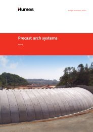
3-pin precast arches<br />
<strong>Humes</strong>' precast arch system is a high performance <strong>and</strong><br />
cost effective tunnel solution. A large range of custom<br />
designed 3-pin arches have been developed which are<br />
ideal for a variety of complex heavy loading criteria <strong>and</strong><br />
internal envelopes.<br />
A wide range of 3-pin arches have been used for reclaim<br />
tunnels in mining applications. They are designed to suit<br />
coal <strong>and</strong> other mineral stockpiles up to 45 metres.<br />
The 3-pin arch is a soil-structure interaction system<br />
where the backfill of the specified zone contributes to<br />
the load carrying capacity of the arch <strong>and</strong> becomes part<br />
of the structure. Its optimised geometry <strong>and</strong> the unique<br />
pinned joint allows it to bear <strong>and</strong> pass heavy load to<br />
the foundation.<br />
Applications<br />
• Reclaim tunnels<br />
• Conveyor tunnels<br />
• Escape tunnels<br />
• Underpasses<br />
Features <strong>and</strong> benefits<br />
• Designed to meet the mine’s designated design life<br />
<strong>and</strong> can exceed 100 years.<br />
• Delivered in segments to suit light cranes.<br />
• Require minimal maintenance since:<br />
- the combination of backfill <strong>and</strong> overfill protects the<br />
arch element<br />
- it has no exposed metal nor bolting system.<br />
• Openings for ventilation, escape accesses <strong>and</strong> intake<br />
valves can be easily accommodated.<br />
• Grades <strong>and</strong> curved tunnels can be achieved using the<br />
same type arch profile.<br />
• A unique jointing system without any overlapping,<br />
staggering, bolting or cast in-situ joints.<br />
• Self supported during installation, does not require<br />
scaffolding or support of backfill.<br />
• Easy to clean <strong>and</strong> maintain as conveyor belts can be<br />
attached to the internal soffit of the arch allowing<br />
sufficient clearance for service vehicles to pass beneath.<br />
• Fewer units are required for installation as most arch<br />
units are 1.8 m to 2.5 m wide.<br />
• Arches can be installed with minimum disruption to<br />
conveyor operation.<br />
<strong>Tunnel</strong> <strong>and</strong> <strong>shaft</strong> <strong>solutions</strong> 19<br />
<strong>Tunnel</strong> <strong>and</strong> <strong>shaft</strong> <strong>solutions</strong>
Product range<br />
<strong>Humes</strong> 3-pin arches are custom-made to suit specific<br />
project requirements. They are designed to accommodate<br />
the defined envelope, where the function of the tunnel<br />
<strong>and</strong> loads are applied.<br />
<strong>Humes</strong> in-house design team can assist in choosing<br />
the most economical 3-pin arch profile (some st<strong>and</strong>ard<br />
profiles are shown in Figure 17 below). We will conduct<br />
both linear <strong>and</strong> non-linear 3D analysis to define<br />
structure suitability, an example of this is shown in<br />
Figure 18 below.<br />
Figure 17 – 3-pin arch profiles<br />
11,000<br />
10,000<br />
9,000<br />
8,000<br />
7,000<br />
6,000<br />
5,000<br />
4,000<br />
3,000<br />
2,000<br />
1,000<br />
0<br />
8,000<br />
7,000<br />
6,000<br />
5,000<br />
4,000<br />
3,000<br />
Figure 18 – 3D design analysis<br />
20 <strong>Tunnel</strong> <strong>and</strong> <strong>shaft</strong> <strong>solutions</strong><br />
2,000<br />
1,000<br />
0<br />
1,000<br />
2,000<br />
3,000<br />
4,000<br />
5,000<br />
6,000<br />
7,000<br />
8,000
Arch system components<br />
A range of precast concrete products are usually provided<br />
as part of the arch structure along with a selection of<br />
retaining wall structures including:<br />
• precast concrete feeder chambers to fit intake valves<br />
• sp<strong>and</strong>rel walls which run parallel to the arch, retaining<br />
the backfill at each end of the tunnel. They are<br />
designed to match the arch profile.<br />
• wing walls which are placed at each end of the<br />
sp<strong>and</strong>rel wall to retain the backfill <strong>and</strong> support the<br />
sp<strong>and</strong>rel walls.<br />
<strong>Tunnel</strong> <strong>and</strong> <strong>shaft</strong> <strong>solutions</strong> 21<br />
Top:<br />
Arch system with<br />
sp<strong>and</strong>rel wall <strong>and</strong><br />
wing walls<br />
Middle:<br />
Sp<strong>and</strong>rel wall<br />
Bottom:<br />
Wing walls<br />
<strong>Tunnel</strong> <strong>and</strong> <strong>shaft</strong> <strong>solutions</strong>
Top <strong>and</strong> bottom:<br />
Construction<br />
of a box culvert<br />
mine portal<br />
Opposite page:<br />
Jacking pipe<br />
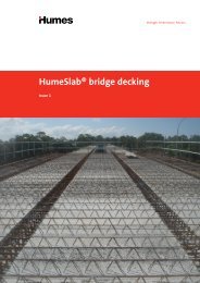
Box culverts<br />
<strong>Humes</strong> manufactures extra large span box culverts with<br />
spans <strong>and</strong> leg heights up to 6 metres. For additional<br />
strength, prestressed units <strong>and</strong> post-tensioning are<br />
also available.<br />
A complete precast base <strong>and</strong> crown unit can be supplied<br />
for fast <strong>and</strong> easy installation. This will minimise the<br />
need for cast in-situ concrete, especially for remote<br />
mining sites.<br />
Box culverts can also be jacked underneath railways <strong>and</strong><br />
roads or slid into a pre-excavated tunnel.<br />
Applications<br />
• Portal entries - provide safe ingress <strong>and</strong> egress for mine<br />
<strong>and</strong> construction sites<br />
• Conveyer tunnels<br />
• Escape tunnels<br />
• Railways <strong>and</strong> roads<br />
• Drainage for haul roads<br />
Features <strong>and</strong> benefits<br />
• Designed to withst<strong>and</strong> explosion loads <strong>and</strong> impact<br />
from rock that may fall from a cut face.<br />
• Designed to take heavy mining vehicle loads.<br />
• Blast doors can be fitted into units as required.<br />
• Custom made to suit project specific envelopes.<br />
• Easy to install, no backfilling or jointing of units is<br />
required for structure stability.<br />
• Can be installed to meet site grade condition.<br />
• Conveyor belts are easily attached to the internal<br />
surface of the crown.<br />
22 <strong>Tunnel</strong> <strong>and</strong> <strong>shaft</strong> <strong>solutions</strong>
Jacking pipes<br />
<strong>Humes</strong> leads the industry <strong>and</strong> develops world class<br />
jacking pipes ideally suited for use with modern, closed<br />
faced microtunnelling systems.<br />
We provide a comprehensive range of both steel<br />
reinforced concrete <strong>and</strong> vitrified clay jacking pipes. They<br />
are available in a variety of sizes, classes <strong>and</strong> joint types<br />
to suit various applications <strong>and</strong> installation methods.<br />
Our jacking pipes are available in the following ranges;<br />
Steel reinforced concrete pipe from DN300 to DN3600<br />
<strong>and</strong> vitrified clay pipe from DN150 to DN1200.<br />
Reinforced concrete pressure pipes are designed for the<br />
combined effects of the external load <strong>and</strong> internal (in<br />
service) pressure. Australian/New Zeal<strong>and</strong> St<strong>and</strong>ard<br />
AS/NZS 4058:2007 Precast Concrete Pipes (Pressures<br />
<strong>and</strong> Non-Pressure) gives a minimum requirement for<br />
factory test pressure of 120% of working pressure in the<br />
pipeline. STEINZEUG KERAMO vitrified clay jacking pipes<br />
are manufactured <strong>and</strong> inspected in accordance with<br />
European St<strong>and</strong>ard EN 295.<br />
The jacking technique<br />
(microtunnelling)<br />
Pipe jacking is a method of tunnel construction where<br />
hydraulic jacks are used to thrust specially made pipes<br />
through the ground behind a shield machine, from<br />
launch <strong>shaft</strong> to receival <strong>shaft</strong>.<br />
The term microtunnelling is also often used to describe<br />
this method of pipe installation.<br />
Pipe jacking is used to install conduits below ground for a<br />
variety of applications including:<br />
• sewerage pipelines<br />
• stormwater pipelines<br />
• road <strong>and</strong> rail culverts<br />
• pressure pipelines<br />
• as a sleeve pipe for other utility pipelines (water,<br />
sewage, <strong>and</strong> electricity <strong>and</strong> communication cables)<br />
• pipe replacement <strong>and</strong> relining<br />
<strong>Tunnel</strong> <strong>and</strong> <strong>shaft</strong> <strong>solutions</strong> 23<br />
<strong>Tunnel</strong> <strong>and</strong> <strong>shaft</strong> <strong>solutions</strong>
Benefits of pipe jacking<br />
Technical<br />
• Inherent strength of lining.<br />
• Smooth internal finish giving good flow characteristics.<br />
• No requirement for secondary lining.<br />
• Considerably less joints than a segmental tunnel.<br />
• Prevention of ground water ingress by use of pipes<br />
with sealed flexible joints.<br />
• Provision of invert channels in larger pipes to contain<br />
the dry weather flow of a sewer in a combined system.<br />
Safety<br />
Pipe jacking is an inherently safer method than open<br />
trench construction or when considering the risks<br />
associated with deep, large section, open excavations:<br />
• Major reduction in man-hours, opportunities for<br />
accidents to occur are less with pipe jacking.<br />
• In busy urban centres, trenchless operation<br />
will not interfere with pedestrian <strong>and</strong> motor<br />
traffic movements.<br />
• There is significant reduction in the risk of injury as a<br />
result of utility strikes <strong>and</strong> interface with the public.<br />
• Less risk of settlement.<br />
Figure 19 – Typical pipe jacking set up<br />
Crane to<br />
lower pipes<br />
into position<br />
24 <strong>Tunnel</strong> <strong>and</strong> <strong>shaft</strong> <strong>solutions</strong><br />
Launch <strong>shaft</strong> with hydraulic jacks<br />
Jacking direction<br />
Economic<br />
• Less affected by weather condition<br />
• Less risk of settlement<br />
• Minimal surface disruption<br />
• Minimal reinstatement<br />
• Reduced requirement for utilities diversions in<br />
urban areas<br />
Environmental<br />
There are substantial environmental benefits to be<br />
gained by the use of pipe jacking techniques when<br />
compared with the traditional open trench approach:<br />
• Typically the trenchless method will reduce the<br />
quantities of incoming <strong>and</strong> outgoing materials,<br />
with a consequent reduction in tipping of spoil <strong>and</strong><br />
quarrying of imported stone fill. This in turn leads to<br />
reduced vehicle movements <strong>and</strong> subsequently less<br />
associated disruption.<br />
• Minimal surface disruption <strong>and</strong> reinstatement.<br />
• Trenchless will not harm existing vegetation.<br />
• Noise, dirt <strong>and</strong> smell are minimised.<br />
Source: An introduction to pipe jacking <strong>and</strong> microtunelling design<br />
– Pipe Jacking Association UK<br />
Detail – Intermediate jacking station<br />
Trail pipe<br />
Rubber<br />
rings<br />
Jacking direction<br />
St<strong>and</strong>ard pipe<br />
Lubrication port<br />
Working face with<br />
jacking shield<br />
Timber joint packer<br />
Lead pipe (steel can)<br />
Jacks<br />
Thrust ring<br />
St<strong>and</strong>ard pipe<br />
Intermediate jacking station<br />
to assist longer drives Receival <strong>shaft</strong>
Steel reinforced concrete pipes<br />
(SRCP)<br />
<strong>Humes</strong> is Australia’s leading manufacturer of SRCP.<br />
We have a wide range of diameters, lengths <strong>and</strong><br />
strengths available. Our SRCP has a proven track record<br />
<strong>and</strong> can be custom designed for applications such as<br />
drainage, sewage, water supply <strong>and</strong> irrigation.<br />
A milestone was achieved when <strong>Humes</strong>' DN2100,<br />
fixed steel collar pipes were jacked 1,030 m without<br />
any intermediate <strong>shaft</strong>s on the Northern Pipeline<br />
Interconnector – Stage 2, SEQ (refer to our case study on<br />
this project for further details).<br />
Benefits of reinforced concrete jacking pipes<br />
Optimal strength<br />
<strong>Humes</strong> SRCP are manufactured <strong>and</strong> factory tested for<br />
quality to AS/NZS 4058:2007 "Precast concrete pipes<br />
(Pressure <strong>and</strong> Non-pressure)":<br />
• A concrete pipe is a rigid pipe system that relies<br />
mostly on the strength of the pipe <strong>and</strong> is only slightly<br />
dependent on the strength derived from the soil<br />
envelope. The inherent strength of concrete pipe can<br />
compensate for site problems not designed for, such as<br />
construction shortcomings <strong>and</strong> higher fill heights <strong>and</strong><br />
trench depths.<br />
• Concrete pipes are less susceptible to damage<br />
during construction, <strong>and</strong> maintain their shape by<br />
not deflecting.<br />
• All concrete pipe strengths are st<strong>and</strong>ardised<br />
by AS/NZS 4058 “Precast Concrete Pipes”. Concrete<br />
pipes are strength-tested by the manufacturer to proof<br />
loads, or test loads, as nominated by the st<strong>and</strong>ard for<br />
particular diameter <strong>and</strong> class.<br />
• Steel reinforcement in concrete pipes adds<br />
significantly to their inherent strength. The steel<br />
reinforcement is shaped into cages by automatic cage<br />
welding machines. The machines ensure that the<br />
reinforcement cages are dimensionally correct <strong>and</strong><br />
have tight enginereed tolerances.<br />
Durable<br />
<strong>Humes</strong> SRCP has a number of concrete properties that<br />
influence long service life. These properties are:<br />
• Ultimate compressive strength: <strong>Humes</strong> SRCP<br />
compressive strength is usually in the range of up<br />
to 60 MPa <strong>and</strong> above. The strength of the pipe is<br />
a result of the materials used in the concrete mix,<br />
the mix design, manufacturing techniques <strong>and</strong> the<br />
curing process.<br />
• Low water absorption, below 4%, due to the density<br />
<strong>and</strong> impermeability of the concrete used <strong>and</strong><br />
manufacturing process. AS/NZS 4058-2007 specifies<br />
a maximum allowable absorption of 6% for all<br />
concrete pipes.<br />
• A low water/cement (W/C) ratio of below 0.35. The<br />
W/C ratio is considered a trademark for durable<br />
concrete pipe, particularly as high compressive<br />
strength is related to this criterion.<br />
• High alkalinity is controlled by cementitious content<br />
maintained by a proper mix design, material properties<br />
as well as the manufacturing <strong>and</strong> curing process.<br />
• Concrete pipe aggregates, both coarse <strong>and</strong> fine, meet<br />
the requirements of AS 2758. Aggregates are a key<br />
element in producing quality concrete <strong>and</strong> in turn,<br />
quality pipe.<br />
Source: Concrete Pipe Facts, Concrete Pipe Association of<br />
Australasia, www.cpaa.asn.au/concrete-pipe-facts.html<br />
<strong>Tunnel</strong> <strong>and</strong> <strong>shaft</strong> <strong>solutions</strong> 25<br />
<strong>Tunnel</strong> <strong>and</strong> <strong>shaft</strong> <strong>solutions</strong>
Fixed steel collar pipes<br />
A wide robust range is available from DN300 to DN3000<br />
inclusive. They are a custom designed reinforced concrete<br />
jacking pipe incorporating a single wide jacking face<br />
including timber packers, a secure steel collar cast<br />
onto the pipe <strong>and</strong> a flexible watertight joint. All these<br />
being essential for longer pipe jacks <strong>and</strong> unstable<br />
ground conditions.<br />
Applications<br />
The fixed steel collar jacking pipes provides high axial<br />
load transfer capacity <strong>and</strong> a flexible watertight joint. This<br />
is the ideal jacking pipe for all stormwater, sewerage,<br />
sleeve pipe <strong>and</strong> jacked low pressure pipeline applications.<br />
Steel collar types<br />
<strong>Humes</strong> offer two different types of fixed steel collars:<br />
the S type which is fitted into pipes up to DN700 <strong>and</strong> the<br />
J type fitted into remaining sizes (mainly from DN800 to<br />
DN3000). The steel collar b<strong>and</strong>s are fabricated to high<br />
tolerances to ensure optimum joint performance.<br />
Both steel collars include a water stop hydro-seal to<br />
prevent ingress of water between the b<strong>and</strong> <strong>and</strong> the<br />
concrete pipe wall.<br />
Elastomeric seal<br />
The elastomeric seal is located with the corrugated<br />
steel collar in the S type collar b<strong>and</strong>, factory secured<br />
internally to the steel socket b<strong>and</strong> with adhesive. While,<br />
in the J type the seal is retained within the accurately<br />
formed recess on the pipe spigot.<br />
Both unique designs will ensure that the elastomeric seal<br />
remains in place in compression even if joint deflection<br />
occurs. The joint integrity remains intact when subjected<br />
to either internal or external hydraulic pressure.<br />
A muck ring is fitted within the J type joint; limiting the<br />
ingress of soil into the joint during jacking. The muck ring<br />
will be compressed by the end of the steel collar.<br />
Watertight joint – (External pressure testing)<br />
<strong>Humes</strong> have undertaken external pressure testing of<br />
deflected joints with external hydrostatic pressures up<br />
to 400 kPa without visible leaks. On this basis, fixed<br />
steel collar jacking pipes are rated for 250 kPa external<br />
pressure for the joint deflections shown in Figures 22<br />
<strong>and</strong> 23 on page 29. <strong>Humes</strong> can design pipes for higher<br />
external pressure ratings if required.<br />
Bentonite or grout injection fittings<br />
Pipes can be supplied with or without threaded sockets<br />
<strong>and</strong> plugs, which are cast into the pipe wall in locations<br />
to meet the project specific requirements for grout <strong>and</strong>/<br />
or lubrication injection.<br />
Figure 20 – S type joint profile Figure 21 – J type joint profile<br />
26 <strong>Tunnel</strong> <strong>and</strong> <strong>shaft</strong> <strong>solutions</strong>
Inert thermoplastic linings<br />
<strong>Humes</strong> are able to supply the J type steel collar jacking<br />
pipes complete with corrosion protection linings (either<br />
High Density Polyethylene (HDPE) or Plastiline®- Polyvinyl<br />
Chloride (PVC)) in accordance with Water Services<br />
Association of Australia (WSAA) st<strong>and</strong>ard specification<br />
WSA113. These linings are a proven method of concrete<br />
protection against H S attack in trunk sewers.<br />
2<br />
Secondary sealing recess<br />
All J type steel collar jacking pipes are supplied with a<br />
recess on the internal pipe ends which allows for locating<br />
a flexible sealant, applied internally after installation,<br />
Table 4 – Features <strong>and</strong> benefits<br />
Features Benefit to asset owner Benefit to contractor<br />
Elastomeric seal Watertight joint<br />
Prevents ingress or egress of water <strong>and</strong> soil<br />
surrounding the pipes <strong>and</strong> allows pressure grouting<br />
of the excavated annulus at the completion of<br />
jacking (if required).<br />
Steel collar fixed to<br />
pipe with in-built<br />
water stop<br />
Corrugated collar<br />
recess (S type)<br />
Deep spigot groove<br />
(J type)<br />
Single wide<br />
jacking face<br />
Muck ring<br />
(J type)<br />
Collar material<br />
The designer has many options for the grade of<br />
steel to suit the intended design life in the installed<br />
environment of the pipe. Generally, mild steel is<br />
considered suitable for in-ground conditions <strong>and</strong> a<br />
non-aggressive environment.<br />
Permanent seal location<br />
The seal remains in place throughout the design<br />
life of the pipeline providing a long-term watertight<br />
structure under external groundwater pressures or<br />
ground movement.<br />
Efficient construction<br />
Long drives, lower construction costs <strong>and</strong> less<br />
disturbance to above-ground activities.<br />
Maintain watertight joint<br />
After installation the muck ring protects the rubber<br />
ring <strong>and</strong> the steel collar to maintain watertightness.<br />
Internal joint recess Additional sealing options<br />
The recess is shaped to allow retention of a flexible<br />
sealant if secondary joint sealing is required.<br />
if required by the project designer for isolation of the<br />
joint from the pipeline environment (see Figure 21 on<br />
page 26). The combination of mild steel collars with internal<br />
joint gap sealant can provide a cost effective solution in<br />
certain ground conditions.<br />
Intermediate jacking stations<br />
<strong>Humes</strong> have st<strong>and</strong>ard designs for intermediate jacking<br />
stations <strong>and</strong> these include trail <strong>and</strong> lead pipes for all<br />
diameters DN1000 to DN2000. The arrangement of these<br />
pipes at the intermediate jacking station is shown in<br />
Figure 19 on page 24.<br />
Flexibility<br />
Allows joint rotation without damage to the<br />
pipe joint.<br />
Watertight joint<br />
Lubrication fluids are retained in the excavated<br />
annulus without loss of fluid or pressure.<br />
Secure system<br />
Steel collar will remain watertight <strong>and</strong> secured<br />
in place during jacking, even in variable<br />
ground conditions.<br />
Efficient jointing<br />
Rapid pipe jointing ensures operational efficiency in<br />
the jacking pit.<br />
Restrained seal<br />
Ensures that the seal remains in place during<br />
jointing <strong>and</strong> jacking with external pressure from<br />
groundwater or lubrication injection.<br />
Long drives<br />
The wide face on the pipe end enables transfer of<br />
high jacking forces through the centerline of the<br />
pipe wall enabling accurate steering <strong>and</strong> long drives.<br />
Maintain watertight joint<br />
Prevents ingress of soil into joint during jacking.<br />
No spalling<br />
Prevents spalling of inside concrete face if the packer<br />
is displaced during jacking.<br />
<strong>Tunnel</strong> <strong>and</strong> <strong>shaft</strong> <strong>solutions</strong> 27<br />
<strong>Tunnel</strong> <strong>and</strong> <strong>shaft</strong> <strong>solutions</strong>
Optimal strength<br />
<strong>Humes</strong> fixed collar jacking pipes, both with S <strong>and</strong> J type<br />
collar, are designed with steel reinforcement placed for<br />
optimal strength, which combined with the strength <strong>and</strong><br />
durability of <strong>Humes</strong> concrete pipes, provides an excellent<br />
jacking pipe. Steel reinforced concrete jacking pipes are<br />
capable of withst<strong>and</strong>ing higher jacking loads.<br />
The jacking load capacity of st<strong>and</strong>ard pipes for a range of<br />
joint deflections is illustrated in Figures 22 <strong>and</strong> 23 on the<br />
following page. Pipes with higher jacking loads <strong>and</strong>/or<br />
joint deflections can be designed for specific projects.<br />
28 <strong>Tunnel</strong> <strong>and</strong> <strong>shaft</strong> <strong>solutions</strong><br />
Jacking design <strong>and</strong> forces<br />
The Concrete Pipe Association of Australasia (CPAA)<br />
publication, Jacking Design Guidelines is a recommended<br />
guide to calculate <strong>and</strong> define jacking forces. The guide<br />
can be downloaded by visiting;<br />
www.cpaa.asn.au/CPAA-Online-Shop.html<br />
Jacking forces <strong>and</strong> lateral displacement off line <strong>and</strong><br />
level have to be recorded at regular intervals of jacking<br />
distance (not exceeding 200 mm or every 90 seconds).<br />
Ensure that jacking forces are maintained within the<br />
limits specified in Figures 22 <strong>and</strong> 23 on the following<br />
page. If circumstances cause a jacking force/deflection<br />
combination outside of these limits, hold the jacking<br />
operation <strong>and</strong> contact <strong>Humes</strong> for assistance.
Figure 22 – S type jacking pipes deflection curves<br />
Maximum jacking force (tonnes)<br />
300<br />
250<br />
200<br />
150<br />
100<br />
50<br />
0<br />
0.10 0.20 0.30 0.40 0.50 0.60 0.70 0.80<br />
DN300<br />
DN350<br />
DN400<br />
Figure 23 – J type jacking pipes deflection curves<br />
Maximum jacking force (tonnes)<br />
2,500 2500<br />
2,250 2250<br />
2,000 2000<br />
1,750 1750<br />
Maximum Jacking Force (Tonnes)<br />
1,500 1500<br />
1,250 1250<br />
1,000 1000<br />
750<br />
500<br />
250<br />
DN800 DN900 DN1000<br />
Maximum joint deflection (degrees)<br />
DN450<br />
J Series Jacking Pipes<br />
DN500<br />
0.90 1.00 1.10 1.20 1.30<br />
DN600<br />
DN700<br />
0<br />
0.10 0.20 0.30 0.40 0.50 0.60 0.70 0.80 0.90 1.00 1.10<br />
Maximum<br />
Maximum<br />
Joint<br />
joint<br />
Deection<br />
deflection<br />
(Degrees)<br />
(degrees)<br />
0<br />
0.10 0.20 0.30 0.40 0.50 0.60 0.70 0.80 0.90 1.00 1.10 1.20<br />
DN800 DN900 DN1000 DN1100 DN1200 DN1350 DN1500 DN1650 DN1800 DN2100 DN2400 DN2500<br />
DN2700 DN3000<br />
DN1100 DN1200 DN1350 DN1500<br />
DN1650 DN1800 DN2100 DN2400 DN2500 DN2700 DN3000<br />
1.20<br />
<strong>Tunnel</strong> <strong>and</strong> <strong>shaft</strong> <strong>solutions</strong> 29<br />
<strong>Tunnel</strong> <strong>and</strong> <strong>shaft</strong> <strong>solutions</strong>
Table 5 – Fixed steel collar pipes dimensions, mass, jacking loads <strong>and</strong> deflections<br />
Nominal<br />
diameter<br />
Internal<br />
diameter<br />
'A'<br />
(mm)<br />
t<br />
Pw<br />
Pt<br />
C<br />
External<br />
diameter<br />
'B'<br />
(mm)<br />
Detail<br />
Wall<br />
thickness<br />
'T'<br />
(mm)<br />
D<br />
Effective<br />
length<br />
'L'<br />
(mm)<br />
Min.<br />
joint<br />
packer<br />
'Pt/Pw'<br />
(mm)<br />
Length<br />
'C'<br />
(mm)<br />
Steel<br />
collar<br />
ID<br />
'D'<br />
(mm)<br />
Thickness<br />
't'<br />
(mm)<br />
Pipe mass<br />
(kg)<br />
Max.<br />
jacking<br />
load<br />
(tonnes)<br />
300 300 430 65 2,400 3/40 50 412 1.5 500 100 S<br />
350 350 480 65 2,400 3/40 50 462 1.5 550 115 S<br />
400 400 540 70 2,400 3/40 50 522 1.5 660 135 S<br />
450 450 606 78 2,400 3/40 50 588 1.5 725 165 S<br />
500 500 672 86 2,400 3/40 50 654 1.5 1,000 225 S<br />
600 600 774 87 2,400 6/60 80 752 2 1,190 240 S<br />
700 700 876 88 2,400 6/60 80 854 2 1,380 280 S<br />
800 800 1,000 100 2,360 12/65 120 989 4 1,800 500 J<br />
900 900 1,110 105 2,360 12/70 120 1,099 4 2,100 500 J<br />
1,000 1,000 1,220 110 2,360 12/75 120 1,209 4 2,400 515 J<br />
1,100 1,100 1,332 116 2,360 12/80 120 1,321 4 2,800 565 J<br />
1,200 1,200 1,450 125 2,360 12/90 120 1,439 4 3,300 650 J<br />
1,350 1,350 1,626 138 2,320 16/90 160 1,611 6 4,000 755 J<br />
1,500 1,500 1,800 150 2,320 16/100 160 1,785 6 4,800 840 J<br />
1,600 1,600 1,940 170 2,985 16/110 160 1,911 8 7,500 1,020 J<br />
1,650 1,650 1,974 162 2,320 16/110 160 1,959 6 5,700 925 J<br />
1,800 1,800 2,150 175 2,320 16/125 160 2,135 6 6,700 1,050 J<br />
2,100 2,100 2,500 200 2,985 16/160 160 2,481 8 12,050 1,440 J<br />
2,400 2,374 2,783 204 2,985 16/175 175 2,759 10 12,950 1,485 J<br />
2,500 2,500 3,000 250 2,985 16/195 175 2,977 10 16,650 2,000 J<br />
2,700 2,636 3,096 230 2,985 16/175 175 3,073 10 16,150 1,900 J<br />
3,000 2,972 3,472 250 2,985 16/195 175 3,449 10 19,700 2,220 J<br />
30 <strong>Tunnel</strong> <strong>and</strong> <strong>shaft</strong> <strong>solutions</strong><br />
Swiftlift® anchors<br />
L<br />
T<br />
A<br />
B<br />
Collar<br />
type
Loose steel collar pipes<br />
<strong>Humes</strong> offer two types of loose steel collar SRCP jacking<br />
pipes, butt joint <strong>and</strong> in-wall joint. They are available from<br />
DN300 to DN3000 (st<strong>and</strong>ard range DN300 to DN2100).<br />
The steel collar is not attached to the pipe (cast with)<br />
but rather is fitted onto the pipe before installation. The<br />
collars can be supplied by either <strong>Humes</strong> or the contractor.<br />
Butt joint pipes<br />
Butt joint jacking pipes incorporate a single wide jacking<br />
face. External recesses at each end of the pipe allow for a<br />
rolled steel collar to be located between adjacent pipes,<br />
providing the necessary shear connection (see Figure 24).<br />
• Applications<br />
Butt joint jacking pipes can provide a cost effective<br />
solution for typically short length applications<br />
where only limited flexibility is required <strong>and</strong> a soil or<br />
watertight joint is not required. This pipe is also suited<br />
to sleeve pipe applications for road <strong>and</strong> rail crossings<br />
where the annulus between the utility pipeline <strong>and</strong><br />
conduit is to be filled with grout after installation.<br />
Refer to Table 7 – Selection of jacking pipes (page 33),<br />
which provides a summary of capabilities for each<br />
of the different types of jacking pipes for different<br />
requirements <strong>and</strong> applications.<br />
In-wall joint pipes<br />
In-wall joint jacking pipes are available from DN1200<br />
to DN3600 (st<strong>and</strong>ard range DN1200 to DN2100). In-wall<br />
joint jacking pipes incorporate a concrete socket formed<br />
in the wall of the pipe, a rubber ring located on the pipe<br />
spigot <strong>and</strong> timber packers on one or both joint faces<br />
(see Figure 25).<br />
• Applications<br />
In-wall joint jacking pipes are an economical viable<br />
alternative for typically short length applications<br />
where a flexible watertight joint is required, however,<br />
this type of joint can have limitations in jacking<br />
load transfer. A J type pipe should be specified in<br />
these situations.<br />
Figure 24 – Butt joint profile Figure 25 – In-wall joint profile<br />
Steel collar Steel collar<br />
<strong>Tunnel</strong> <strong>and</strong> <strong>shaft</strong> <strong>solutions</strong> 31<br />
<strong>Tunnel</strong> <strong>and</strong> <strong>shaft</strong> <strong>solutions</strong>
Table 6 – Loose steel collar pipe range<br />
Nominal<br />
diameter<br />
Internal<br />
diameter<br />
Selection of jacking pipes<br />
In-wall joint Butt joint<br />
External<br />
diameter<br />
mm<br />
Internal<br />
diameter<br />
The most basic requirements for all jacking pipes is<br />
that they must be capable of supporting the excavation<br />
(earth <strong>and</strong> traffic loads), transferring axial load, providing<br />
a shear connection between adjacent pipes <strong>and</strong> joint<br />
flexibility that allows for each pipe to follow the path<br />
excavated in front of the shield.<br />
External<br />
diameter<br />
DN300 280 362<br />
DN375 363 445<br />
DN475 438 534<br />
DN525 518 616<br />
DN600 586 698<br />
DN675 653 781<br />
DN750 730 864<br />
DN825 790 946<br />
DN900 875 1029<br />
DN975 951 1,111<br />
DN1050 1,026 1,194<br />
DN1200 1,200 1,500 1,163 1,359<br />
DN1350 1,324 1,524<br />
DN1500 1,452 1,676<br />
DN1650 1,596 1,842<br />
DN1800 1,756 2,006<br />
DN1950 1,920 2,220 1,930 2,198<br />
DN2100 2,088 2,388 2,096 2,388<br />
Notes:<br />
1. Alternative internal diameters (<strong>and</strong> external diameters) may be available to suit project<br />
specific requirements, contact <strong>Humes</strong> for assistance.<br />
2. St<strong>and</strong>ard range is equivalent to load class 4 pipes.<br />
3. Contact <strong>Humes</strong> for in-wall joint pipes in this range.<br />
32 <strong>Tunnel</strong> <strong>and</strong> <strong>shaft</strong> <strong>solutions</strong><br />
In addition, jacking pipes may need to prevent ingress of<br />
surrounding soil, groundwater, lubricants or grouts <strong>and</strong><br />
provide a joint capable of withst<strong>and</strong>ing internal pressure<br />
in sewerage or pressure pipeline applications.<br />
Jacking pipes must meet both the needs of the<br />
contractor <strong>and</strong> asset owner who is usually represented<br />
by the pipeline designer. Table 7 opposite provides a<br />
summary of the capabilities of each of our types of<br />
jacking pipes for different requirements <strong>and</strong> applications.
Table 7 – Selection of jacking pipes<br />
Stakeholder<br />
Jacking pipe<br />
requirements or<br />
application<br />
Fixed steel collar Loose steel collar<br />
S type J type Butt joint In-wall joint<br />
Asset owner St<strong>and</strong>ard size class DN300 – DN700 DN800 – DN3000 DN300 – D2100 DN1200 – DN2100<br />
Asset<br />
owners <strong>and</strong><br />
contractors<br />
Extended diameter<br />
range*<br />
Incorporation of inert<br />
thermoplastic lining<br />
External grouting Suitable for short<br />
lengths<br />
Internal pressure test<br />
capability (kPa)‡<br />
Application of<br />
internal secondary<br />
sealants<br />
DN800 Up to DN3600 DN2250 – DN3000 DN2250 – DN3600<br />
N/A Available DN900 > Available<br />
Ideally suited Not suitable Limited suitability†<br />
90 150 § N/A 90<br />
N/A Suitable Not suitable Limited suitability<br />
Sewerage pipelines Limited suitability || Ideally suited Not suitable Suitable<br />
Stormwater pipelines Ideally suited Ideally suited Limited suitability Suitable<br />
Road <strong>and</strong> rail culverts Ideally suited Ideally suited Limited suitability Suitable<br />
Sleeve pipe<br />
applications<br />
Length of jacked<br />
pipeline (m)<br />
External pressure test<br />
capability §§<br />
Ideally suited Ideally suited Limited suitability # Suitable<br />
0 – 50†† < DN1000: 0 – 150<br />
DN1000 – DN3000:<br />
no limit‡‡<br />
0 – 50** 0 – 50<br />
90 250 N/A 90<br />
Jacking force transfer Excellent Excellent Good Moderate<br />
Intermediate jacking<br />
stations pipes<br />
N/A Available DN900 –<br />
DN3000<br />
To be provided by<br />
contractor<br />
Contractors Open face shields Suitable Suitable Suitable Suitable<br />
Closed face pressure<br />
shields<br />
Lubrication along<br />
length of pipeline<br />
To be provided by<br />
contractor<br />
Ideally suited Ideally suited Not suitable Limited suitability<br />
N/A Ideally suited Not suitable |||| Limited suitability<br />
Notes:<br />
* Refer to <strong>Humes</strong> for availability.<br />
† Grout pressures need to be carefully monitored.<br />
‡ Test to AS/NZS 4058: 2007.<br />
§ Higher pressures are possible with certain diameters – refer to <strong>Humes</strong> for advice if higher pressures are required.<br />
|| If corrosive sewage gases are expected consider using vitrified clay jacking pipes distributed by <strong>Humes</strong>.<br />
# The butt joint jacking pipe is suitable for short length drives in certain soil conditions if the annulus between the concrete sleeve pipe <strong>and</strong> the product pipe is grouted.<br />
This grout should also flow into the annulus between the sleeve pipe <strong>and</strong> the excavated ground.<br />
†† Intermediate jacking stations are not available <strong>and</strong> length is mainly limited by installation equipment. Some pipe jacking contractors may be able to achieve longer<br />
lengths of individual drives in certain soil conditions. Refer to jacking pipe contractor for advice for longer drives.<br />
‡‡ The maximum length will be controlled by installation equipment rather than pipe capability.<br />
** Lack of joint flexibility largely controls maximum length. This could be extended in certain soil conditions.<br />
§§ There is no published test method for external joint testing of reinforced concrete pipes. External pressures due to lubrication or grouting can be well in excess of<br />
ground water pressures.<br />
|||| For lubrication to be effective, the annulus between the external diameter of the pipe <strong>and</strong> the excavated soil needs to be filled. The butt joint pipe may not provide an<br />
effective sealed joint.<br />
<strong>Tunnel</strong> <strong>and</strong> <strong>shaft</strong> <strong>solutions</strong> 33<br />
<strong>Tunnel</strong> <strong>and</strong> <strong>shaft</strong> <strong>solutions</strong>
Load class<br />
Jacking pipes, as opposed to pipes laid in open<br />
excavations, are subjected to both jacking forces,<br />
external earth loads <strong>and</strong> life loads (permanent loads)<br />
<strong>and</strong> all of these have to be considered when specifying<br />
the pipes.<br />
The effect of the jacking force on the pipe barrel is<br />
small on account of the high compressive strength of<br />
the concrete. The joint, however, must be considered<br />
because the joint cross-section is smaller, as a rule, than<br />
that of the barrel <strong>and</strong> the jacking force is transferred<br />
eccentrically across the joint.<br />
The external earth load on the barrel is equal to or<br />
smaller than the trench load on a pipe bedded in a<br />
trench of same width as the excavation (i.e. the outside<br />
diameter of the pipe plus a margin for over-excavation).<br />
The jacking method of installation, therefore, is very<br />
efficient from an external load point of view since the<br />
external earth load is smaller than both trench <strong>and</strong><br />
embankment load on pipes of the same diameter under<br />
the same height of fill.<br />
As such a minimum Class 4 pipe is usually recommended<br />
although in some short length drives a Class 3 may<br />
be suitable. The Class 4 pipe to Australian St<strong>and</strong>ard<br />
AS/NZS 4058: 2007 has very similar strength<br />
requirements to load classes specified for jacking pipes<br />
in European <strong>and</strong> Japanese St<strong>and</strong>ards.<br />
AS/NZS 4058: 2007 outlines the technique for<br />
determining the permanent vertical loads acting on<br />
pipes installed using pipe jacking. The jacking pipe<br />
is installed underground into undisturbed natural<br />
ground where the soil’s natural cohesion contributes to<br />
arching over the pipe. Where the calculation includes<br />
the effects of arching due to soil cohesion extensive soil<br />
investigations should be carried out to determine the<br />
appropriate design soil properties.<br />
The jacking installation results in a recommended<br />
bedding factor between two <strong>and</strong> three that is used to<br />
determine the minimum suitable pipe class required due<br />
to permanent loads.<br />
34 <strong>Tunnel</strong> <strong>and</strong> <strong>shaft</strong> <strong>solutions</strong><br />
The higher value is recommended when the annulus<br />
between the pipe <strong>and</strong> ground is grouted. Grouting<br />
of this annulus with a suitable cementitious grout is<br />
recommended in most installations as any voids could<br />
create a drainage path external to the pipeline which in<br />
turn could lead to soil erosion, lowering of ground water<br />
tables <strong>and</strong>, in aggressive soil conditions, an increased risk<br />
of corrosion of pipe materials.<br />
The axial loading from the pipe jacking is not directly<br />
included in the selection of the pipe load class. Timber<br />
packers are placed between the jacking faces of the<br />
concrete pipes to avoid high stresses that could result<br />
from direct concrete to concrete contact. The axial load<br />
capacity of the concrete pipe is determined based on<br />
the minimum pipe wall thickness, concrete strength,<br />
properties of the timber packers <strong>and</strong> the deflections that<br />
can be expected at pipe joints during installation.<br />
The allowable jacking forces <strong>and</strong> associated maximum<br />
joint deflections are calculated in accordance with<br />
the Concrete Pipe Association of Australasia (CPAA)<br />
publication, Jacking Design Guidelines.<br />
Source: Jacking Design Guidelines, Concrete Pipe Association<br />
of Australasia.<br />
Jacking design <strong>and</strong> forces<br />
The CPAA publication, Jacking Design Guidelines, is a<br />
recommended guide to calculate <strong>and</strong> define jacking<br />
forces. The guide can be downloaded by visiting;<br />
www.cpaa.asn.au/CPAA-Online-Shop.html<br />
Jacking force <strong>and</strong> lateral displacement off line <strong>and</strong><br />
level have to be recorded at regular intervals of jacking<br />
distance (not exceeding 200 mm or every 90 seconds).<br />
Ensure that jacking forces are maintained within the<br />
specified limits. If circumstances cause a jacking force/<br />
deflection combination outside of these limits, hold the<br />
jacking operation <strong>and</strong> contact <strong>Humes</strong> for assistance.
Vitrified clay pipes<br />
<strong>Humes</strong> vitrified clay jacking pipes are manufactured by<br />
STEINZEUG-KERAMO (STEINZEUG Abwassersysteme<br />
GmbH) <strong>and</strong> inspected in accordance with the European<br />
st<strong>and</strong>ard for vitrified clay pipes, fittings <strong>and</strong> joints for<br />
drains <strong>and</strong> sewers - EN 295.<br />
Features <strong>and</strong> benefits<br />
Watertightness<br />
The joints are tested in accordance with EN 295, which<br />
means that they are guaranteed to be watertight at<br />
0.5 bar, including the angular deflections <strong>and</strong> radial<br />
loads specified in the st<strong>and</strong>ard. They are also tested<br />
in accordance with ZPWN 2951 <strong>and</strong> ATV A142, with<br />
guaranteed watertightness at 2.4 bar. Watertightness<br />
is also tested at an external pressure of 6 bar, which<br />
provides a high level of security against penetration of<br />
soil slurries <strong>and</strong> bentonite.<br />
Corrosion resistance<br />
Vitrified clay material is resistant to all types of chemicals<br />
over the entire wall thickness. The resistance of the<br />
vitrified clay material <strong>and</strong> seals is tested using chemicals,<br />
including sulphuric acid at pH 0 <strong>and</strong> NaOH at pH 14, in<br />
conformance with EN 295 <strong>and</strong> ZPWN 295.<br />
High mechanical strength<br />
Vitrified clay jacking pipes generally have greater wall<br />
thicknesses than corresponding st<strong>and</strong>ard vitrified clay<br />
sewer pipes, that results in high crown pressure ratings<br />
<strong>and</strong> high resistance to ground <strong>and</strong> traffic loads.<br />
Strength in the length direction is the most important<br />
factor for jacking pipes, because they must withst<strong>and</strong> the<br />
high jacking forces necessary to overcome the resistance<br />
of the cutting face <strong>and</strong> the external pipe surface.<br />
According to the EN 295 st<strong>and</strong>ard, the longitudinal<br />
compressive strength of the surfaces that transfer the<br />
force between pipe sections must be at least 75 N/mm².<br />
STEINZEUG-KERAMO guarantees a value of at least<br />
100 N/mm². That is higher than the values stated for<br />
other types of current jacking material. It allows very<br />
high jacking forces to be used, although this capability is<br />
only partially utilised in practice. The glazed outer surface<br />
of the pipe strongly reduces friction between the pipe<br />
<strong>and</strong> the surrounding soil.<br />
High abrasion resistance<br />
Vitrified clay has high abrasion resistance, which<br />
is equally true for the glaze <strong>and</strong> the rest of the<br />
wall. Abrasion values encountered in the tests are<br />
approximately 0.08 mm, which is much lower than<br />
the typical abrasion values of 0.2 mm to 0.5 mm after<br />
100,000 load cycles measured using the Darmstadt test<br />
as specified in the EN 295 st<strong>and</strong>ard or the maximum<br />
value of 0.25 mm in the ZPWN 295 st<strong>and</strong>ard. Abrasion<br />
does not accelerate even with extended load cycles, such<br />
as up to 400,000, in contrast to what is often suggested<br />
in data sheets for competitive materials. The depth of<br />
abrasion remains limited to 0.3 - 0.8 mm after 400,000<br />
cycles. Compared with the large wall thicknesses of<br />
vitrified clay jacking pipes, that represents a negligible<br />
loss of wall thickness.<br />
1. ZPWN 295 is an internal manufacturer st<strong>and</strong>ard of<br />
STEINZEUG-KERAMO.<br />
<strong>Tunnel</strong> <strong>and</strong> <strong>shaft</strong> <strong>solutions</strong> 35<br />
<strong>Tunnel</strong> <strong>and</strong> <strong>shaft</strong> <strong>solutions</strong>
Right:<br />
Vitrified clay jacking<br />
pipe installation<br />
Resistance to high-pressure cleaning<br />
The requirement included in the ZPWN 295 st<strong>and</strong>ard<br />
is met (resistance with regard to a st<strong>and</strong>ardised<br />
maintenance cleaning test at 120 bar <strong>and</strong> a deblocking<br />
test at 340 bar). Here again, vitrified clay scores<br />
considerably better than many other types of material.<br />
Temperature resistance<br />
Pipes <strong>and</strong> seals are tested at up to 70 °C. Vitrified clay<br />
pipes can tolerate even higher temperatures.<br />
Long service life<br />
After being properly installed, vitrified clay pipe requires<br />
very little maintenance. As vitrified clay scores very<br />
high with respect to all the requirements that must be<br />
imposed on sewer pipes, vitrified clay pipes have very<br />
long service lives. The important properties mentioned<br />
above do not degrade over time. This is especially true<br />
for jacking pipes, because they are structurally over<br />
dimensioned for their subsequent use <strong>and</strong> optimally<br />
bedded in the ground.<br />
36 <strong>Tunnel</strong> <strong>and</strong> <strong>shaft</strong> <strong>solutions</strong>
Product range<br />
The entire range of vitrified clay jacking pipes DN200 to<br />
DN1200 are fitted with a stainless steel coupling which<br />
has a high chrome <strong>and</strong> nickel content <strong>and</strong> a relatively<br />
significant molybdenum content. This coupling is highly<br />
resistant to corrosion in aggressive soils (acids, chlorides<br />
<strong>and</strong> halogens).<br />
Two different types of stainless steel couplings are used,<br />
Type 1 <strong>and</strong> Type 2.<br />
DN200 to DN300 with Type 1 stainless steel coupling<br />
• The moulded elastomer seal is integrated into the ring.<br />
• The packing ring, which transmits the jacking force is<br />
made from elastomer for diameters up to DN300 <strong>and</strong><br />
forms a unit with the moulded sealing ring.<br />
• Pipes are sawn at both ends to yield parallel end faces.<br />
• The spigot ends are milled. The precision ground<br />
spigots as for larger dimension jacking pipes permit a<br />
safe internal working pressure of 2.4 bar.<br />
• The sealing capabilities of the coupler due to its special<br />
design not only guarantees joint integrity, but ensures<br />
full protection from the ingress of matter during the<br />
jacking process.<br />
Figure 26 – Typical vitrified clay pipe jacking set up<br />
DN400 to DN1200 with Type 2 stainless steel coupling<br />
• The moulded rubber seal is integrated in a<br />
milled groove.<br />
• The packing ring, which transmits the jacking force,<br />
is made from particle board <strong>and</strong> is prefitted to<br />
the coupling.<br />
• Pipes are sawn <strong>and</strong> milled at both ends to yield parallel<br />
end faces.<br />
• For diameters DN600 <strong>and</strong> above a clamping<br />
(prestressing) ring is fitted at each spigot end. This ring<br />
increases the permissible jacking force <strong>and</strong> provides<br />
additional protection in case of poorly controlled<br />
steering motions during jacking or when angular<br />
deflections occur due to variations in soil conditions.<br />
• Intermediate re-usable jacking stations can be used<br />
with diameters of DN600 <strong>and</strong> above. This is advisable<br />
for long jacking distances <strong>and</strong> when jacking forces<br />
exceeding the specified limits are anticipated. The<br />
intermediate jacking stations are coupled to the spigot<br />
ends of the pipes <strong>and</strong> recovered in the receival pit or an<br />
intermediate <strong>shaft</strong>.<br />
The trenchless mode of construction<br />
At the present time two remote steered methods<br />
for the construction of underground sewers<br />
are in use. These two methods are<br />
described below in accordance with ATV<br />
bentonite suspensions are used, special s<strong>and</strong><br />
removal equipment is used. The drive for the<br />
cutting head <strong>and</strong> for the steering cylinders are<br />
located in the jacking shield. In general this<br />
<strong>Tunnel</strong> <strong>and</strong> <strong>shaft</strong> <strong>solutions</strong> 37<br />
<strong>Tunnel</strong> <strong>and</strong> <strong>shaft</strong> <strong>solutions</strong>
Figure 27 – Joint profiles for DN200 to DN300 pipe with Type 1 coupling<br />
Table 8 – Dimensions for DN200 to DN300 pipe with Type 1 coupling (refer Figure 27 above)<br />
DN<br />
Internal<br />
Pipe<br />
end<br />
d 1<br />
± 5 d 3 d M<br />
200 199 244<br />
250 250 322<br />
300 299 374<br />
+ 2<br />
Pipe<br />
dimensions Coupling<br />
Pipe<br />
body Length e d k<br />
276<br />
+ 0<br />
l 1<br />
± 1<br />
mm<br />
990 49<br />
- 2 - 6 - 1<br />
+ 0<br />
360<br />
+ 0 990<br />
1,990<br />
48<br />
- 1 - 6 - 0<br />
+ 0<br />
406<br />
+ 0 990<br />
1,990<br />
48<br />
- 1 -10 - 0<br />
+ 3<br />
± 1<br />
s k<br />
± 0.2<br />
Notes:<br />
1. * Permissible jacking force for automatic recording <strong>and</strong> control, safety factors 2 <strong>and</strong> 1.6.<br />
2. Compressive strength = 100 N/mm 2 .<br />
3. Bending tensile strength = 14 N/mm 2 .<br />
4. Supplied with wooden pressure transfer ring according to EN 312 P5.<br />
5. The ground spigot ends (d 3 ) are trimmed ca. 2 x 2 mm.<br />
38 <strong>Tunnel</strong> <strong>and</strong> <strong>shaft</strong> <strong>solutions</strong><br />
l 1<br />
e<br />
d 1<br />
+ 3<br />
+ 3<br />
Detail<br />
2<br />
d 3 d M d k d zi<br />
2<br />
b k<br />
± 1.5<br />
s k<br />
d z<br />
± 1<br />
b k<br />
Pressure<br />
transfer ring<br />
d za<br />
± 0.5<br />
d z<br />
d zi<br />
± 0.5<br />
Jacking direction<br />
Max.<br />
jacking<br />
force*<br />
Min.<br />
crushing<br />
load<br />
Average<br />
weight<br />
kN kN/m kg/m<br />
267.8 1.5 103 10 241 205 350 80 60<br />
342.8 1.5 106 10 320 257 810 110 105<br />
395.8 2.0 106 10 372 309 1,000 120 125
Figure 28 – Joint profiles for DN400 to DN1200 pipe with Type 2 coupling<br />
Table 9 – Dimensions for DN400 to DN1200 pipe with Type 2 coupling (refer Figure 28 above)<br />
DN<br />
Bevel d m min. 45°<br />
l 1<br />
Internal<br />
d 1 d 3<br />
Pipe dimensions Coupling<br />
Pipe<br />
end Pipe body Length<br />
+0<br />
d M<br />
400 400 + 6 528 556 + 0 984<br />
- 6 - 12 1,984<br />
-1<br />
e<br />
l 1<br />
± 1<br />
mm<br />
e<br />
± 2<br />
d k<br />
± 1<br />
s k<br />
± 0.2<br />
b k<br />
± 1<br />
Pressure transfer<br />
ring<br />
d z<br />
± 1<br />
d za<br />
± 1<br />
d zi<br />
± 1<br />
Max.<br />
jacking<br />
force *<br />
Min.<br />
crushing<br />
load<br />
Average<br />
weight<br />
kN kN/m kg/m<br />
65 536 3 130 16 518 413 2,350 160 240<br />
500 498 + 7.5 632 661 + 0 1,984 65 640 3 130 16 624 513 3,000 140 295<br />
- 7.5 - 15<br />
600 599 + 9 723 766 + 0 1,981 70 731 3 143 19 713 615 3,100 120 350<br />
- 9 - 18<br />
700 695 + 12 827 870 + 0 1,981 70 837 4 143 19 816 715 3,300 140 434<br />
- 12 - 24<br />
800 792 + 12 921 970 + 0 1,981 70 931 4 143 19 911 823 3,700 128 507<br />
- 12 - 24<br />
1000 1,056 + 15 1,218 1,275 + 0 1,981 70 1,230 5 143 19 1,208 1,077 5,700 120 855<br />
- 15 - 30<br />
1200 1,249 + 18 1,408 1,475 + 0 1,981 80 1,422 6 163 19 1,397 1,277 6,400 114 990<br />
- 18 - 36<br />
Notes:<br />
1. * Permissible jacking force for automatic recording <strong>and</strong> control, safety factors 2 <strong>and</strong> 1.6.<br />
2. Compressive strength = 100 N/mm 2 .<br />
3. Bending tensile strength = 14 N/mm 2 .<br />
4. Supplied with wooden pressure transfer ring according to EN 312 P5.<br />
5. The ground spigot ends (d 3 ) are trimmed ca. 2 x 2 mm.<br />
6. For diameters DN600 <strong>and</strong> above a prestressing (clamping) ring is fitted at each spigot end.<br />
d 1<br />
Rubber seal<br />
d 3 d M d k d za d zi<br />
Prestressing ring 6<br />
S k<br />
b k<br />
d z<br />
Particle board<br />
Max. d m on this side<br />
Jacking direction<br />
<strong>Tunnel</strong> <strong>and</strong> <strong>shaft</strong> <strong>solutions</strong> 39<br />
<strong>Tunnel</strong> <strong>and</strong> <strong>shaft</strong> <strong>solutions</strong>
Right:<br />
Milled end of<br />
adaptor pipe <strong>and</strong><br />
socketed end of<br />
st<strong>and</strong>ard pipe<br />
Connection to st<strong>and</strong>ard pipes <strong>and</strong><br />
access chambers<br />
Three different components are used to connect vitrified<br />
clay jacking pipes to st<strong>and</strong>ard vitrified clay pipelines <strong>and</strong><br />
access chambers.<br />
1. Adaptor pipe for DN200 to DN600 pipes<br />
The adaptor pipe is used for connection of vitrified clay<br />
jacking pipes to open trench vitrified clay pipes normal/<br />
high strength class or access chambers. They consist of<br />
1.0 m long jacking pipes with a coupling on one end <strong>and</strong><br />
the other end milled to the external diameter of the pipe<br />
to which the adaptor is to be connected.<br />
Figure 29 – Adaptor pipe for DN200 to DN600 pipes<br />
b k<br />
d z<br />
Coupling type 1 or 2<br />
d k d 1 d 3 d M<br />
1,000 mm<br />
vitrified clay jacking pipe to a vitrified clay so<br />
eted pipe is provided by the use of an bush<br />
to equal out the different diameters. Then, w<br />
e = 180 mm<br />
Table 10 – Dimensions for adaptor pipe for DN200 to DN600 pipes (refer Figure 29 above)<br />
DN<br />
Internal<br />
d 1<br />
Pipe end<br />
(normal strength)<br />
d 3<br />
Pipe dimensions<br />
+0<br />
+0<br />
d3 -1 -1<br />
mm<br />
Figure 30 – Connection of adaptor pipe to access chamber<br />
Grinded on a length e = 180 mm<br />
Pipe end<br />
(high strength) Pipe body<br />
d M<br />
Length<br />
(mm)<br />
l1 ± 1<br />
Average weight<br />
(kg/piece)<br />
250 250 +3 299 318 360 +0 1,000 105<br />
-3 -6<br />
300 299 +5 355 376 406 +0 1,000 125<br />
-5 -10<br />
400 400 +6 486 492 556 +0 1,000 240<br />
-6 -12<br />
500 498 +7.5 581 609 661 +0 1,000 295<br />
-7.5 -15<br />
600 601 +9 687 721 766 +0 1,000 305<br />
-9 -18<br />
40 <strong>Tunnel</strong> <strong>and</strong> <strong>shaft</strong> <strong>solutions</strong><br />
d 3<br />
of the<br />
jacking<br />
pipe<br />
d M<br />
d 3 of the<br />
st<strong>and</strong>ard vc<br />
pipe (normal<br />
or high<br />
strength)<br />
1,000 mm<br />
Inspection chamber with vitrified clay invert<br />
BKK ring<br />
P ring
2. M-seal <strong>and</strong> bush ring<br />
Another way of achieving the transition from a vitrified<br />
clay jacking pipe to an open trench vitrified clay socketed<br />
pipe of different external diameter is by using an M-seal<br />
<strong>and</strong> bush ring.<br />
The bush ring is used to equal out the outside diameters<br />
of the two pipes. The M-seal is a metal b<strong>and</strong>ed flexible<br />
coupling providing a watertight <strong>and</strong> reliable connection<br />
between the jacking <strong>and</strong> trench pipes.<br />
3. Short length pipes<br />
Connection of vitrified clay jacking pipes to access<br />
chambers can also be achieved using short length,<br />
350 mm to 500 mm pipes. Three different types of short<br />
length pipes are available to suit various applications <strong>and</strong><br />
installation methods.<br />
Type A – One end sawn flat <strong>and</strong> the other with a<br />
steel coupling.<br />
Type B – Both ends are sawn flat.<br />
Type C – One end sawn flat <strong>and</strong> one spigot end.<br />
An M-seal <strong>and</strong> bush ring is used to connect these three<br />
types together.<br />
Figure 32 – Short length pipes<br />
d k<br />
b k<br />
300 to 1399 x x x x x<br />
Bush types according to outside diameter differences.<br />
To combine with M seals.<br />
21<br />
Figure 31 – M-seal <strong>and</strong> bush ring<br />
Jacking pipe<br />
Sawn flat spigot<br />
Type A Type B Type C<br />
l 1<br />
d 1<br />
d M<br />
l 1<br />
d 1<br />
85<br />
190<br />
M-seal<br />
St<strong>and</strong>ard vc pipe<br />
Bush ring<br />
d M d 1 d 2<br />
l 1<br />
e<br />
<strong>Tunnel</strong> <strong>and</strong> <strong>shaft</strong> <strong>solutions</strong> 41<br />
Left:<br />
M-seal with<br />
bush ring<br />
<strong>Tunnel</strong> <strong>and</strong> <strong>shaft</strong> <strong>solutions</strong>
Top:<br />
CMP on-site<br />
manufacturing<br />
Bottom:<br />
CMP used in a<br />
culvert application<br />
Corrugated Metal Pipe (CMP)<br />
<strong>Humes</strong> Corrugated Metal Pipe (CMP) is a helically wound,<br />
lock seamed corrugated metal pipe <strong>and</strong> is available in<br />
pipe diameters up to 5.1 m, <strong>and</strong> wall thicknesses of<br />
1.6 mm, 2 mm, 2.5 mm, 3 mm <strong>and</strong> 3.5 mm.<br />
CMP is manufactured from Z600 galvanised grade 250<br />
steel in two state-of-the-art profiles TR <strong>and</strong> TRS. Both<br />
of these profiles have higher load bearing capacity<br />
than similar corrugated sinusoidal profiles with TR<br />
outperforming 68 x 13 <strong>and</strong> TRS outperforming both<br />
125 x 25 <strong>and</strong> 75 x 25. It is designed in accordance with<br />
Australian St<strong>and</strong>ards AS 1761-1985 <strong>and</strong> AS 1762-1984<br />
Helical Locked Seamed Corrugated Steel Pipe.<br />
Applications<br />
• Culverts under haul/temporary roads<br />
• Mine <strong>and</strong> conveyor portals<br />
• Safe access to mines <strong>and</strong> construction sites<br />
• Escape tunnels<br />
• Conduit casing<br />
• Ventilation <strong>shaft</strong>s <strong>and</strong> air flow columns<br />
Features <strong>and</strong> benefits<br />
• Large diameters <strong>and</strong> long lengths manufactured<br />
economically on-site minimising freight cost.<br />
• Large diameter pipes eliminate the high installation<br />
cost of multi-plate structures.<br />
• On-site manufacture accommodates order variations<br />
<strong>and</strong> additions, <strong>and</strong> frees up haul roads on mine sites.<br />
• <strong>Humes</strong>’ unique profiles optimise load bearing capacity.<br />
• Where pipes are to be joined, dedicated coupling<br />
b<strong>and</strong>s are supplied providing a secure fit.<br />
• <strong>Humes</strong>’ design team ensure customer’s requirements<br />
are met.<br />
• Large diameter culverts can be laid in live condition<br />
(running streams).<br />
• Installed CMP has high load bearing capacity.<br />
42 <strong>Tunnel</strong> <strong>and</strong> <strong>shaft</strong> <strong>solutions</strong><br />
Figure 33 – CMP profiles<br />
TR profile<br />
TRS profile
Backfilling<br />
CMP is a flexible pipe which replies on soil structure<br />
interaction to maintain its structural stability.<br />
Tables 11 <strong>and</strong> 12 below list the maximum cover for each<br />
of the CMP profiles.<br />
Table 11 – Maximum cover (m) for TR profile<br />
Nominal<br />
internal<br />
diameter<br />
(mm)<br />
Wall thickness<br />
(mm)<br />
1.6 2.0 2.5 3.0<br />
300 ++ ++ x x<br />
375 ++ ++ x x<br />
450 ++ ++ x x<br />
600 ++ ++ ++ x<br />
750 40.5 ++ ++ x<br />
900 34.0 47.5 ++ x<br />
1,050 29.0 40.5 ++ x<br />
1,200 25.5 35.5 45.0 ++<br />
1,350 22.5 31.5 40.0 49.0<br />
1,500 20.5 28.5 36.0 44.5<br />
1,650 18.5 26.0 33.0 40.0<br />
1,800 16.5 23.5 30.0 37.0<br />
1,950 * 20.5 27.0 34.0<br />
2,100 * 18.5 24.0 30.0<br />
2,250 * 16.5 21.5 27.0<br />
2,400 * * 19.0 24.5<br />
2,550 * * 17.0 22.0<br />
2,700 * * * 19.5<br />
2,850 * * * 17.0<br />
3,000 * * * 15.5<br />
Notes:<br />
• Calculations are based on base material steel thickness,<br />
ie without galvanising.<br />
• For minimum cover requirements please contact <strong>Humes</strong><br />
for assistance.<br />
• Soil density 19 kN/m 3 .<br />
• * Denotes unsuitable due to flexibility factor greater than<br />
0.250 mm/N.<br />
• ++ Denotes height of fill greater than 50 m.<br />
• x Denotes not practical for manufacture.<br />
Table 12 – Maximum cover (m) for TRS profile<br />
Nominal<br />
internal<br />
diameter<br />
(mm)<br />
Wall thickness<br />
(mm)<br />
1.6 2.0 2.5 3.0 3.5<br />
900 x x x x x<br />
1,050 x x x x x<br />
1,200 x x x x x<br />
1,350 x x x x x<br />
1,500 x x x x x<br />
1,650 x x x x x<br />
1,800 x x x x x<br />
1,950 16.5 21.5 27.5 33.0 38.5<br />
2,100 15.5 20.0 25.5 30.5 36.0<br />
2,250 14.5 18.5 23.5 28.5 33.5<br />
2,400 13.5 17.5 22.0 26.5 31.5<br />
2,550 12.5 16.5 20.5 25.0 29.5<br />
2,700 12.0 15.5 19.5 23.5 28.0<br />
2,850 11.0 14.5 18.5 22.5 26.5<br />
3,000 10.0 13.5 17.5 21.5 25.0<br />
3,300 * 11.5 15.5 18.5 22.0<br />
3,600 * 10.0 13.5 16.0 19.5<br />
3,900 * * 12.0 14.0 17.0<br />
4,200 * * 8.0 11.0 14.5<br />
4,500 * * * 9.5 12.5<br />
4,800 * * * * 10.5<br />
5,100 * * * * 9.5<br />
Notes:<br />
• Calculations are based on base material steel thickness,<br />
ie without galvanising.<br />
• For minimum cover requirements please contact <strong>Humes</strong><br />
for assistance.<br />
• Soil density 19 kN/m 3 .<br />
• * Denotes unsuitable due to flexibility factor greater than<br />
0.250 mm/N.<br />
• x Denotes not practical for manufacture.<br />
<strong>Tunnel</strong> <strong>and</strong> <strong>shaft</strong> <strong>solutions</strong> 43<br />
<strong>Tunnel</strong> <strong>and</strong> <strong>shaft</strong> <strong>solutions</strong>
Top:<br />
Precast arches<br />
Middle:<br />
HumeDeck®<br />
modular bridge<br />
system<br />
Bottom:<br />
Headwall<br />
Precast <strong>solutions</strong><br />
<strong>Tunnel</strong> <strong>and</strong> <strong>shaft</strong><br />
Access, pipe jacking <strong>and</strong> ventilation <strong>shaft</strong>s<br />
Segmental <strong>shaft</strong>s<br />
One piece <strong>shaft</strong>s<br />
Mine portals <strong>and</strong> reclaim tunnels<br />
Precast arches<br />
Box culverts<br />
Corrugated Metal Pipe (CMP)<br />
Traffic <strong>and</strong> utility tunnels<br />
Segmental tunnel linings<br />
Steel reinforced concrete pipes – jacking<br />
Vitrified clay pipes – jacking<br />
Escape tunnels <strong>and</strong> <strong>shaft</strong>s<br />
Precast arches<br />
Box culverts<br />
Steel reinforced concrete pipes<br />
Corrugated Metal Pipe (CMP)<br />
Stormwater<br />
Sewage transfer <strong>and</strong> storage<br />
Bridge <strong>and</strong> platform<br />
Walling<br />
Potable water supply<br />
Irrigation supply<br />
Traffic management<br />
Cable <strong>and</strong> power management<br />
Rail<br />
Livestock management<br />
44 <strong>Tunnel</strong> <strong>and</strong> <strong>shaft</strong> <strong>solutions</strong>
Contact information<br />
National sales 1300 361 601<br />
humes.com.au<br />
info@humes.com.au<br />
Head Office<br />
18 Little Cribb St<br />
Milton QLD 4064<br />
Ph: (07) 3364 2800<br />
Fax: (07) 3364 2963<br />
Queensl<strong>and</strong><br />
Brisbane/Gold Coast<br />
Ph: (07) 3866 7100<br />
Fax: (07) 3866 7101<br />
Bundaberg<br />
Ph: (07) 4152 2644<br />
Fax: (07) 4152 5847<br />
Rockhampton<br />
Ph: (07) 4924 7900<br />
Fax: (07) 4924 7901<br />
Sunshine Coast<br />
Ph: (07) 5472 9700<br />
Fax: (07) 5472 9711<br />
Toowoomba<br />
Ph: (07) 4694 1420<br />
Fax: (07) 4634 3874<br />
Townsville<br />
Ph: (07) 4758 6000<br />
Fax: (07) 4758 6001<br />
New South Wales<br />
Canberra<br />
Ph: (02) 6285 5309<br />
Fax: (02) 6285 5334<br />
Grafton<br />
Ph: (02) 6644 7666<br />
Fax: (02) 6644 7313<br />
Kempsey<br />
Ph: (02) 6562 6755<br />
Fax: (02) 6562 4235<br />
Lismore<br />
Ph: (02) 6621 3684<br />
Fax: (02) 6622 1342<br />
Newcastle<br />
Ph: (02) 4032 6800<br />
Fax: (02) 4032 6822<br />
Sydney<br />
Ph: (02) 9832 5555<br />
Fax: (02) 9625 5200<br />
Tamworth<br />
Ph: (02) 6763 7300<br />
Fax: (02) 6763 7301<br />
Victoria<br />
Echuca<br />
Ph: (03) 5480 2371<br />
Fax: (03) 5482 3090<br />
Melbourne<br />
Ph: (03) 9360 3888<br />
Fax: (03) 9360 3887<br />
Tasmania<br />
Launceston<br />
Ph: (03) 6335 6300<br />
Fax: (03) 6335 6330<br />
South Australia<br />
Adelaide<br />
Ph: (08) 8168 4544<br />
Fax: (08) 8168 4549<br />
Western Australia<br />
Gnangara<br />
Ph: (08) 9302 8000<br />
Fax: (08) 9309 1625<br />
Perth<br />
Ph: (08) 9351 6999<br />
Fax: (08) 9351 6977<br />
Northern Territory<br />
Darwin<br />
Ph: (08) 8984 1600<br />
Fax: (08) 8984 1614
National sales 1300 361 601<br />
humes.com.au<br />
info@humes.com.au<br />
A Division of Holcim Australia<br />
This <strong>brochure</strong> supersedes all previous literature on this subject. As the specifications <strong>and</strong> details contained in this publication may change please<br />
check with <strong>Humes</strong> Customer Service for confirmation of current issue. This document is provided for information only. Users are advised to<br />
make their own determination as to the suitability of this information for their own specific circumstances. We accept no responsibility for any<br />
loss or damage resulting from any person acting on this information. <strong>Humes</strong> is a registered business name <strong>and</strong> a registered trademark of Holcim<br />
(Australia) Pty Ltd. Plastiline is a registered trademark of Holcim (Australia) Pty Ltd. STEINZEUG KERAMO is a registered trademark of STEINZEUG<br />
Abwassersysteme GmbH. Swiftlift is a registered trademark of ITW Construction Products Australia Pty Ltd.<br />
© August 2012 Holcim (Australia) Pty Ltd ABN 87 099 732 297