Surge Relief Valves for Water - GA Industries
Surge Relief Valves for Water - GA Industries
Surge Relief Valves for Water - GA Industries

Create successful ePaper yourself
Turn your PDF publications into a flip-book with our unique Google optimized e-Paper software.
Made in the<br />
U.S.A.<br />
W-200-D<br />
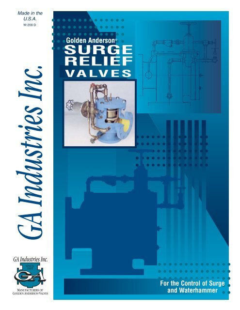
Golden Anderson ©<br />
SURGE<br />
RELIEF<br />
VALVES<br />
For the Control of <strong>Surge</strong><br />
and <strong>Water</strong>hammer
Let Us Help Solve Your <strong>Surge</strong><br />
and <strong>Water</strong>hammer Problems...<br />
GOLDEN-ANDERSON <strong>Surge</strong> <strong>Relief</strong><br />
<strong>Valves</strong> have been protecting municipal<br />
and industrial systems against damaging<br />
surge and waterhammer <strong>for</strong> over 85<br />
years. GOLDEN-ANDERSON <strong>Surge</strong><br />
<strong>Relief</strong> <strong>Valves</strong> are on guard in countless<br />
installations the world over, ready to prevent<br />
sudden, unexpected pressure<br />
surges from causing catastrophic damage<br />
or personal injury.<br />
<strong>GA</strong> <strong>Industries</strong>, Inc., manufacturers of<br />
GOLDEN-ANDERSON automatic control<br />
valves, has an experienced and competent<br />
staff, along with a network of factory<br />
trained representatives, ready to assist<br />
you. Using field-proven computer analysis<br />
of your system data, our engineers can<br />
predict maximum surge intensity and<br />
select the proper GOLDEN-ANDERSON<br />
surge control valves to protect your system<br />
from damage.<br />
The GOLDEN-ANDERSON <strong>Surge</strong><br />
<strong>Relief</strong> Valve is one of many products<br />
available from <strong>GA</strong> <strong>Industries</strong> <strong>for</strong> the control<br />
of waterhammer and surge in water,<br />
wastewater, raw sewage and industrial<br />
2<br />
FREE VIDEO<br />
PRESENTATION<br />
Contact the<br />
factory of<br />
your local<br />
<strong>GA</strong> <strong>Industries</strong><br />
representative<br />
<strong>for</strong> a free showing<br />
of the “SURGE TRILOGY”.<br />
This three-part video explains<br />
how surges develop in simple<br />
pipes, how valve operation affects<br />
surge and how surge and waterhammer<br />
can be controlled using<br />
GOLDEN-ANDERSON automatic<br />
valves.<br />
fluid systems. <strong>GA</strong> <strong>Industries</strong>’ worldwide<br />
reputation <strong>for</strong> quality, service and per<strong>for</strong>mance<br />
insures you will receive sensible,<br />
cost-effective solutions.<br />
<strong>GA</strong> <strong>Industries</strong>, Inc.<br />
Cranberry Township, Pennsylvania
14” FIGURE 6600-D<br />
SURFACE WATER TREATMENT FACILITY, CHANDLER, AZ<br />
INSTALLED 1988 ENGINEER:MALCOLM PIRNIE<br />
12” FIGURE 6600-D<br />
SHOREMONT WTP, MONROE COUNTY (NY) WATER<br />
INSTALLED 1981 ENGINEER:O’BRIEN & GERE<br />
10” FIGURE 6600-D<br />
COLDBROOK PUMP STATION, GRAND RAPIDS, MI<br />
INSTALLED 1989<br />
3<br />
Table of<br />
Contents<br />
Table of Contents . . . . . . . . . . . .Page 3<br />
Installations and Applications <strong>for</strong><br />
<strong>GA</strong> <strong>Surge</strong> <strong>Relief</strong> <strong>Valves</strong><br />
The GOLDEN-ANDERSON . . . . .Page 4<br />
<strong>Surge</strong> <strong>Relief</strong> Valve<br />
Features and Benefits<br />
Differential Piston . . . . . . . . . . . . .Page 5<br />
Operating Principle<br />
How does a <strong>GA</strong> <strong>Surge</strong> . . . . . . . . .Page 6<br />
<strong>Relief</strong> Valve Control<br />
<strong>Water</strong>hammer?<br />
Sizing, Installation . . . . . . . . . . . . .Page 7<br />
Cross Sections, Parts . . . . . . . .Page 8-9<br />
Lists, Materials, Ordering<br />
In<strong>for</strong>mation, Warranty<br />
Dimensions, Weights . . . . . . . . .Page 10<br />
and Specifications<br />
Figure 667 Bronze . . . . . . . . . . .Page 11<br />
<strong>Surge</strong> <strong>Relief</strong>, 1/2” - 2” NPT<br />
Other <strong>GA</strong> <strong>Surge</strong> . . . . . . . . . . .Back Cover<br />
Control Products<br />
Typical Applications of<br />
GOLDEN-ANDERSON<br />
<strong>Surge</strong> <strong>Relief</strong> <strong>Valves</strong><br />
1. Municipal water treatment plants and<br />
pump stations<br />
2. Hydro-electric power plant turbine<br />
bypass<br />
3. Steel mills<br />
4. Process industries<br />
5. Aerospace
Design Features... The GOLDEN-ANDERSON © <strong>Surge</strong><br />
<strong>Relief</strong> Valve has many standard features<br />
that make it the most dependable, versatile<br />
and cost-effective over-pressure protection<br />
device available today!<br />
ANGLE STYLE<br />
GLOBE STYLE<br />
✦<br />
✦<br />
✦<br />
✦<br />
✦<br />
✦<br />
✦<br />
4<br />
SHHHOCKLESS - Unique GOLDEN-ANDER-<br />
SON © vee-ported, differential piston design<br />
provides positive closing power at any working<br />
pressure, excellent throttling and Shhhockless<br />
operation. See next page <strong>for</strong> details.<br />
RESPONSIVE - Large, sensitive pilot opens<br />
valve QUICKLY in response to an over-pressure<br />
condition. It then closes slowly at an<br />
adjustable speed, once pressure subsides.<br />
DEPENDABLE - Oversize hard brass pilot<br />
piping minimizes clogging and kinking.<br />
Standard wye-strainer and bronze pilot with<br />
resilient seat <strong>for</strong> long, reliable service. (All<br />
stainless steel pilot available.)<br />
PRESSURE RATING - Standard with heavyduty<br />
iron body rated <strong>for</strong> a MINIMUM of 250 psi<br />
working pressure to 12”, 150 psi in larger<br />
sizes, matching ductile iron pipe rating.<br />
(Alternate materials available <strong>for</strong> higher pressures.)<br />
INSTALLATION VERSATILITY - Standard in<br />
angle or globe style body with Class 125 or<br />
Class 250 flanges, as required. Other flange<br />
ratings are available <strong>for</strong> higher pressures. Can<br />
be installed in any orientation <strong>for</strong> piping convenience.<br />
SIZE RANGE - Manufactured in size 2-1/2”<br />
through 36”, <strong>for</strong> adequate surge protection<br />
regardless of system size.<br />
EASE OF MAINTENANCE - Valve body stays<br />
in line while all internal components can be<br />
removed, inspected and/or replaced through a<br />
single top cover. Standard isolating valves on<br />
pilot lines allow quick pilot service.<br />
✦<br />
PRE-SET - Each valve is factory tested and<br />
preset at the specified relieving pressure, but<br />
can be easily field-adjusted if required.
...The Golden Advantage<br />
The heart of all GOLDEN-ANDERSON © pilot-operated automatic control valves is<br />
the “vee-ported differential piston” main valve using pipeline pressure <strong>for</strong> its power.<br />
Rugged and reliable, this unique design has many advantages over other valve types,<br />
particularly when protection of a critical piping system is required, as in a <strong>Surge</strong> <strong>Relief</strong><br />
valve.<br />
CLOSING POWER<br />
Differential piston design<br />
provides positive operation,<br />
even at very low working<br />
pressure. Assures surge relief<br />
valve will re-close when<br />
pressure returns to normal.<br />
CAPACITY<br />
Streamlined and<br />
full-ported, provides<br />
maximum relieving<br />
capacity <strong>for</strong> system<br />
protection.<br />
CONSTRUCTION<br />
Standard heavy-duty iron body in angle or<br />
globe style in a wide range of sizes. All<br />
bronze internals with only one moving part.<br />
Drop-tight renewable resilient seat and long<br />
wearing seals. Indicator rod shows valve<br />
position at a glance.<br />
5<br />
INLET<br />
CONTROL<br />
Long vee-ports provide linear<br />
control over the full capacity<br />
of the valve, but are especially<br />
effective at low flow, eliminating<br />
“chatter” when the valve<br />
only opens a small amount to<br />
relieve minor surges.<br />
CAVITATION RESISTANCE<br />
Since a surge relief valve usually discharges<br />
to atmosphere, high velocity and cavitation<br />
likely occur each time the valve opens. The<br />
design of the <strong>GA</strong> valve protects the seat<br />
from both the damaging effects of cavitation<br />
and the high velocity of the discharge fluid.
How Does a <strong>GA</strong> <strong>Surge</strong> <strong>Relief</strong><br />
Valve Work?<br />
OPERATION<br />
System pressure is applied through the valve's inlet<br />
to the bottom area of the piston and through a pilot line<br />
connected from the valve's inlet to the top area of the<br />
piston. Pressure is also applied to the underside of the<br />
pilot's diaphragm through a line which senses the system<br />
pressure. When this pressure is less than the pilot's<br />
spring setting, the pilot is closed, trapping inlet pressure<br />
on top of the piston.<br />
Since the area above the piston is as much as twice<br />
the underside, the main valve is held closed due to the<br />
hydraulic <strong>for</strong>ce generated by the difference in areas.<br />
When system pressure against the underside of the<br />
pilot diaphragm exceeds the pilot spring setting, the pilot<br />
opens, quickly exhausting water from above the main<br />
valve's piston. System pressure against the underside of<br />
the piston immediately lifts the piston to permit water to<br />
escape through the main valve, thereby limiting the pressure<br />
increase. The valve will open only as much as necessary<br />
to limit further pressure rise.<br />
Once the system pressure subsides below the pilot<br />
spring adjustment, the pilot closes. System pressure<br />
accumulates above the large end of the piston through<br />
the closing speed needle valve to close the main valve<br />
at the pre-set rate.<br />
6<br />
ADJUSTMENT<br />
Although the valve is factory pre-set at the desired relief<br />
setting, its setting can be changed easily by turning the<br />
pilot handwheel. To have the valve open at a higher pressure,<br />
turn the handwheel clockwise. To have it open at a<br />
lower pressure, turn the handwheel counter clock-wise.<br />
Usually, the setting should be about 10% higher than the<br />
highest normal system pressure.<br />
OPENING SPEED<br />
The opening speed of the valve is determined by the<br />
speed at which water escapes from above the piston. All<br />
GOLDEN-ANDERSON © <strong>Surge</strong> <strong>Relief</strong> <strong>Valves</strong> are<br />
equipped with extra large pilots <strong>for</strong> very fast opening.<br />
CLOSING SPEED<br />
The relief valve will close at any desired speed by simply<br />
regulating the flow of line pressure water to the top of the<br />
piston through the closing speed control needle valve.<br />
Throttle the needle valve <strong>for</strong> slower closing speed; open<br />
the needle valve <strong>for</strong> faster closing speed. A slow closing<br />
is recommended to prevent secondary surges and valve<br />
chatter.<br />
This valve will:<br />
1. Open quickly at pre-set pressure to dissipate damaging surges.<br />
2. Close at adjustable speed immediately upon pressure subsidence below pilot setting<br />
3. Have a pilot to provide <strong>for</strong> adjustment of pressure at which the valve will open.<br />
Figure 6700-D<br />
Globe Design<br />
Illustrated<br />
OVER PRESSURE CONTROL<br />
PILOT (TURN HANDWHEEL<br />
CLOCKWISE TO RAISE<br />
PRESSURE)<br />
IMPULSE LINE CONNECTED TO<br />
INLET THROUGH STOP VALVE<br />
STOP VALVES<br />
NORMALLY OPEN<br />
NEEDLE VALVE CONTROLS<br />
CLOSING SPEED<br />
STRAINER
Where<br />
TOTAL<br />
FLOW in<br />
GPM is:<br />
Below 350<br />
350 to 700<br />
700 to 1000<br />
1000 to 2000<br />
2000 to 4500<br />
4500 to 8000<br />
8000 to 13000<br />
l3000 to 19000<br />
19000 to 24000<br />
24000 to 30000<br />
30000 to 40000<br />
40000 to 50000<br />
50000 to 70000<br />
Above 70000<br />
PUMP<br />
TYPICAL<br />
INSTALLATION<br />
<strong>GA</strong>TE<br />
Suggested<br />
ANGLE<br />
STYLE<br />
Valve Size<br />
See Page 11<br />
2-1/2”<br />
3”<br />
4”<br />
6”<br />
8”<br />
10”<br />
12”<br />
14”<br />
16”<br />
18”<br />
20”<br />
24”<br />
Consult Factory<br />
Consult Factory <strong>for</strong> Special<br />
Recommendations<br />
<strong>GA</strong>TE REQUIRED FOR POSITIVE<br />
PUMP SUCTION HEAD ONLY<br />
GOLDEN-ANDERSON<br />
ANGLE ELECTRIC<br />
CHECK VALVE<br />
HEADER<br />
Approximate Full<br />
Open Seat Area<br />
Flow Through<br />
<strong>GA</strong> Valve*<br />
4.9 sq.in.<br />
7.1 sq.in.<br />
12.6 sq.in.<br />
28.3 sq.in.<br />
50.3 sq.in.<br />
78.5 sq.in.<br />
113.1 sq.in.<br />
153.9 sq.in.<br />
201.1 sq. in.<br />
254.5 sq. in.<br />
314.2 sq. in.<br />
452.4 sq. in.<br />
*Any multiple of smaller sized valves having a collective<br />
total seat area equal to a single larger sized<br />
valve may be substituted <strong>for</strong> the larger valve. Each of<br />
the smaller valves, when set at incrementally higher<br />
relieving pressures, provide a more flexible control of<br />
the system with a minimum discharge of water.<br />
GOLDEN-ANDERSON ©<br />
FIGURE 600<br />
SURGE RELIEF<br />
<strong>GA</strong>TE VALVE<br />
DISCHARGE TO<br />
DRAIN OR WET-WELL<br />
7<br />
<strong>Surge</strong> <strong>Relief</strong><br />
Valve Sizing<br />
<strong>Surge</strong> relief valves normally are not sized to pass<br />
the entire output of the pump(s), but rather to discharge<br />
only that portion of the total flow necessary to<br />
limit the increase in system pressure to a tolerable<br />
level. There<strong>for</strong>e, the surge relief valve is usually several<br />
sizes smaller than the pipe on which it is<br />
installed.<br />
<strong>Surge</strong> relief valves only open as far as necessary<br />
to pass the flow required to limit the pressure.<br />
There<strong>for</strong>e, it is better to oversize the valve as it will<br />
merely throttle in a partially open position if less than<br />
its full capacity is required to limit the pressure.<br />
Conversely, undersizing a surge relief valve could<br />
adversely affect its ability to protect the system.<br />
The chart to the left is offered as a general guideline<br />
<strong>for</strong> sizing GOLDEN-ANDERSON © <strong>Surge</strong> <strong>Relief</strong><br />
<strong>Valves</strong>.<br />
Many factors other than total system flow (line<br />
diameter, length, material, pumps, system pressure,<br />
etc.) will affect the potential surge conditions <strong>for</strong> a<br />
system. Whenever possible, it is recommended that<br />
the overall system characteristics be examined to<br />
confirm the proper relief valve requirements. Contact<br />
the factory or our local representative <strong>for</strong> a copy of<br />
the <strong>GA</strong> <strong>Industries</strong> "<strong>Surge</strong> Analysis Checklist” <strong>for</strong> a<br />
more thorough review of the surge potential conditions<br />
and relief valve sizing.<br />
Installation<br />
The valve as received from the factory is complete<br />
and ready to install. It is only necessary to bolt<br />
the flanged connections to the pipe flanges and set<br />
the closing speed, normally about 1/4 turn open on<br />
initial tests. Otherwise, the valve has been factory<br />
tested and pre-set <strong>for</strong> the desired relieving pressure.<br />
Be<strong>for</strong>e installation, insure all lines are clean and<br />
free of dirt or construction debris.<br />
The valve is installed with system pressure<br />
applied to the inlet and should preferably discharge<br />
to atmosphere, free of exhaust.
<strong>Surge</strong> <strong>Relief</strong> Valve<br />
Globe Body Parts<br />
1. Globe Body<br />
1A. Angle Body<br />
2. Piston<br />
3. Liner<br />
4. Piston Cup<br />
4A. Piston U-Cup<br />
5. Piston Cup Follower<br />
Ring<br />
6. Piston Cup Screws<br />
7. Liner Cup<br />
7A. Liner U-Cup<br />
Note: Part #3 on 10” and<br />
larger size valves is in two<br />
pieces: (#3 Liner & #21<br />
Seat Crown).<br />
Note: U-Cup Seals used<br />
in both Globe and Angle<br />
Body assemblies through<br />
10” size. Flanged cups<br />
used on valves 12” and<br />
larger.<br />
Note: Flanges per<br />
ANSI B16.1<br />
LIST OF PARTS In<strong>for</strong>mation Required When Ordering<br />
8. Liner Cup Follower<br />
Ring<br />
9. Liner Cup Screws<br />
10. Seat Ring Washer<br />
11. Seat Ring Follower<br />
12. Seat Ring Screws<br />
13. Cover<br />
14. Cover Nuts and Bolts<br />
15. Cover Gasket<br />
8<br />
1. Size and quantity of valve(s)<br />
2. Advise angle or globe style and flange rating<br />
3. Advise pressure at which valve(s) are to open<br />
(normally about 10% above highest normal<br />
system pressure)<br />
4. Advise static pressure at valve outlet if not<br />
atmospheric<br />
5. Specify any optional equipment that is to be<br />
installed on the valve<br />
WARRANTY<br />
Interior Design Shown<br />
Illustrates <strong>Valves</strong><br />
2” Through 10” sizes<br />
This <strong>GA</strong> <strong>Industries</strong> product is made of the finest available suitable<br />
materials and every possible precaution has been taken to assure<br />
premium workmanship consistent with established quality control.<br />
<strong>Valves</strong> or parts which are proved faulty due to defective materials<br />
or poor workmanship will be replaced free of charge, F.O.B. our<br />
plant upon presentation of such proof. This warranty shall not<br />
cover the cost of installation and is valid <strong>for</strong> a period of one year<br />
from date of shipment. Specifications are subject to change; certified<br />
prints upon request with order.
Illustration <strong>for</strong> 12”<br />
and larger sizes<br />
16. Indicator Rod<br />
17. Indicator Rod Gland<br />
18. Indicator Packing<br />
19. Indicator Bushing<br />
20. Indicator Lock Nut<br />
21. Seat Crown<br />
LIST OF PARTS<br />
22. Vent Tube<br />
23. Vent Bushing<br />
24. Vent Packing<br />
26. Strainer<br />
29. Needle Valve<br />
30. Stop Valve<br />
(See Page 11 <strong>for</strong> Pilot Parts.)<br />
GENERAL LIST OF MATERIAL<br />
9<br />
32. Cover O-Ring<br />
33. Liner O-Ring<br />
35. Bottom Liner O-Ring<br />
1/2” Pilot ...<strong>Valves</strong> 2-1/2” - 10”<br />
1” Pilot ......<strong>Valves</strong> 12” - 16”<br />
2” Pilot ......<strong>Valves</strong> 18”- Up<br />
PART MATERIAL TRADE NAME OR ASTM SPEC.<br />
Body, Cover<br />
Piston, Liner, Seat Crown, Pilot <strong>Valves</strong><br />
Piston Cup, Liner Cup, Pilot Cups<br />
Seat Washer, Pilot Seats<br />
Follower Rings, Rod, Gland<br />
Bushings,Screws<br />
Gaskets<br />
Cast Iron or Cast Steel*<br />
Bronze or Alloy<br />
Leather or Buna “N”<br />
Rubber or Leather<br />
Alloy or Bronze<br />
Composition<br />
Angle Body Parts<br />
A-126, Class B or A-216-WCB<br />
B-62 or Non-Corrosive Equal<br />
Retan, Buna “N” or Equal<br />
Commercial Retan or Equal<br />
Commercial or Non-Corrosive Equal<br />
Nitrile Rubber & Fibre or Equal<br />
* For pressures above 300 PSI material list changes to suit; i.e., cast steel body and cover, stainless steel<br />
trim, etc. Optional Extra Cost.<br />
We reserve the right to substitute materials which in our opinion are of equal or superior quality, in the<br />
construction of any valve <strong>for</strong> a particular application.
DIN, ISO, BS<br />
OR SPECIAL<br />
FLANGES ARE<br />
AVAILABLE<br />
CONSULT<br />
THE FACTORY<br />
FOR DETAILS<br />
Dimensions and Weights<br />
B<br />
A<br />
Angle Style Globe Style<br />
A C D A D<br />
Figure 6600-D (125# FLG) ✦ Figure 6600-U (250# FLG) Figure 6700-D (125# FLG) ✦ Figure 6700-U (250# FLG)<br />
BODY A B C D WEIGHT<br />
SIZE STYLE IN MM IN MM IN MM IN MM LB KG<br />
2-1/2” Angle 6 152 16 406 13 330 11 279 160 73<br />
Globe 12 305 24 610 4-1/4 108 18 457<br />
3” Angle 6 152 16 406 13 330 11 279 160 73<br />
Globe 12 305 24 610 4-1/4 108 18 457<br />
4” Angle 6-1/2 165 17 432 14 356 12 304 200 91<br />
Globe 13 330 25 635 5-1/4 133 19 483<br />
6” Angle 8-3/4 222 18 457 17 432 14 356 350 159<br />
Globe 18 457 27 686 6-1/2 165 3 584<br />
8” Angle 11-1/4 286 19 483 19 486 15 381 700 318<br />
Globe 24-1/2 622 30 762 8-1/4 210 27 686<br />
10” Angle 14-1/4 362 21-1/2 546 21 533 18 457 1200 546<br />
Globe 26 660 30 762 9-3/4 248 30 765<br />
12” Angle 15-1/2 394 21-1/2 546 24 610 19 483 1500 682<br />
Globe 31 788 39 991 13 330 31 788<br />
14” Angle 16-1/2 419 22 559 27 686 21 533 1700 773<br />
Globe 33 838 41 1041 13 330 36 914<br />
16” Angle 18 457 24 610 30 762 23 584 2300 1046<br />
Globe 36 914 45 1143 13-1/2 343 38 956<br />
18” Angle 20-1/2 521 26 660 30 762 24 610 3600 1636<br />
Globe 40 1016 48 1219 17 432 43 1092<br />
20” Angle 20-1/2 521 24 660 30 762 24 610 3800 1727<br />
Globe 40 1016 48 1219 17 432 43 1092<br />
24” Angle 24 610 32 813 34 864 29 737 6000 2727<br />
Globe 48 1219 53 1346 21 533 49 1245<br />
Above dimensions are approximate and are applicable to standard valves only. "A" dimension includes raised face. Weight identical <strong>for</strong> angle or globe<br />
style. Consult factory <strong>for</strong> larger sizes. Flanges per ANSI B16.1.<br />
SPECIFICATIONS<br />
The surge relief valve shall function to open quickly when the system<br />
pressure exceeds the setting <strong>for</strong> which the pilot is set. The valve<br />
shall close slowly at an adjustable speed once the system pressure<br />
subsides below the setting of the pilot.<br />
The valve body shall be heavy-duty cast iron angle (or globe)<br />
design with integral flanges per ANSI B16. Valve bodies with Class 125<br />
flanges shall have a minimum working pressure of 250 psi to 12” size,<br />
150 psi in larger sizes. Valve bodies with Class 250 flanges shall have<br />
a minimum working pressure of 400 psi to 12” and 300 psi in larger<br />
sizes.<br />
The main valve shall operate on the differential piston principle<br />
such that the area on the underside of the piston is no less than the pipe<br />
area and the area on the upper surface of the piston is greater than the<br />
underside. There shall be no diaphragms in the main valve.<br />
10<br />
B<br />
C<br />
The valve piston shall be guided on its outside over the full length of its<br />
stroke by long stationary vee-ports downstream of the seating surface<br />
to minimize the consequences of throttling. All throttling shall be by the<br />
veeports and not by the seat itself. All internal guiding and sealing surfaces<br />
shall be bronze per ASTM B62.<br />
The valve shall be fully capable of operating in any position without<br />
the use of springs. There shall be no stems, spokes or stem guides<br />
within the waterway. The flow area through the valve shall be no less<br />
than the area of its nominal pipe size.<br />
<strong>Surge</strong> relief valve shall include an all bronze, spring loaded, normally<br />
closed, balanced, diaphragm operated resilient seated pilot valve,<br />
y-strainer, visual position indicator, stop valves and adjustable closing<br />
speed control.<br />
There shall be one flanged cover through which all service can be<br />
accomplished without removing the valve from the line.<br />
<strong>Surge</strong> relief valve shall be Figure 6600 (Angle) or 6700 (Globe) as<br />
manufactured by <strong>GA</strong> <strong>Industries</strong>, Inc., Cranberry Township, PA.
Valve Function<br />
1/2” to 2” <strong>Surge</strong> <strong>Relief</strong> Valve<br />
1” Size Illustrated<br />
STANDARD VALVE: BRONZE BODY WITH BRONZE OR STAINLESS<br />
STEEL STEM AND REPLACEMENT RUBBER SEAT<br />
ALSO AVAILABLE IN STAINLESS STEEL<br />
When Total Flow<br />
in GPM is:<br />
The function of the valve is<br />
to protect water lines against<br />
excessive over pressure in the<br />
system and will close off tightly<br />
when the system pressure is<br />
restored to normal.<br />
Description<br />
The pressure relief valve<br />
shall be of the single seated balanced<br />
type globe body with<br />
threaded inlet and outlet ports. It<br />
shall be diaphragm operated,<br />
spring loaded permitting con-<br />
Figure 667 Sizing<br />
Suggested<br />
Size is:<br />
Less than 35 . . . . . . . . . . . . . . . . . . . .1/2”<br />
35 to100 . . . . . . . . . . . . . . . . . . . . . . . .1”<br />
100 to 350 . . . . . . . . . . . . . . . . . . . . . . .2”<br />
venient adjustment from near<br />
zero to the limit of the spring.<br />
The body shall be of bronze<br />
construction with bronze or<br />
stainless steel stem and furnished<br />
with a replaceable rubber<br />
seat.<br />
Ordering In<strong>for</strong>mation<br />
1. Minimum and maximum inlet<br />
pressure<br />
2. Desired relief pressure setting<br />
Figure Number<br />
The valve shall be the <strong>GA</strong><br />
<strong>Industries</strong> Figure 667.<br />
11<br />
Screwed Ends<br />
FEATURES<br />
1. All bronze construction throughout<br />
2. Screwed connections standard<br />
NPT<br />
3. 1/2” size furnished with union<br />
connections<br />
4. Setting adjustable ± range 15 PSI<br />
5. Cushioned in closing to prevent<br />
hammer<br />
6. Good <strong>for</strong> water, air, gas and oil<br />
7. Extra heavy construction <strong>for</strong><br />
industrial & commercial applications<br />
DIMENSIONS<br />
SIZE 1/2” 1” 2”<br />
A 5 1/4 5 3/4 7<br />
B 2 3 3 1/2<br />
C 15 15 14 1/2<br />
D 5 or 7 7 7<br />
Weight 55 lbs. 40 lbs. 55 lbs.<br />
FIGURE NUMBERS<br />
667-D Inlet Pressures to 175 PSI<br />
667-U Inlet Pressures to 300 PSI<br />
1/2” PARTS LIST<br />
1. Body 11. Stem Nut<br />
2. Rubber Seat 12. Spring<br />
3. Lower 13. Spring<br />
O-Ring Guide<br />
4. Lower Stem 14. Spring Chamber<br />
5. Diaphragm 15. Chamber Screws<br />
Washer 16. Adjusting Screws<br />
6. Upper Stem 17. Screw Locknut<br />
7. Upper O-Ring 18. Handwheel<br />
8. Stem Gasket 19. Handwheel Nut<br />
9. Diaphragm 20. Tail Piece<br />
10. Diaphragm 21. Union Ring<br />
Disc<br />
1” & 2” PARTS LIST<br />
1. Globe Body 12. Spring<br />
2. Rubber Seat 13. Spring Guide<br />
3. Lower O-Ring 14. Spring Chamber<br />
4. Lower Spool 15. Chamber Screws<br />
5. Upper Spool 16. Adjusting Screws<br />
6. Stem 17. Screw Locknut<br />
7. Upper O-Ring 18. Handwheel<br />
8. Body Cap 19. Handwheel Nut<br />
9. Diaphragm<br />
10. Diaphragm Disc<br />
11. Stem Nut
Call or Write <strong>for</strong> In<strong>for</strong>mation on Other <strong>GA</strong> <strong>Industries</strong> <strong>Surge</strong> Control Products<br />
Bulletin W-1740-C Bulletin R-200-A Bulletin ESP-17<br />
Bulletin S-1625-A Bulletin AR-2000 Bulletin S-625-A<br />
PRINTED IN U.S.A. COMM 07/04<br />
9025 MARSHALL ROAD • CRANBERRY TOWNSHIP, PA 16066 USA<br />
PHONE: (724) 776-1020<br />
FAX: (724) 776-1254 AND (724) 625-2170<br />
WEB SITE: www.gaindustries.com<br />
E-MAIL: ga@gaindustries.com<br />
MEMBER<br />
<strong>Water</strong> & Wastewater Equipment<br />
Manufacturers Association, Inc.<br />
ESTABLISHED 1908<br />
MEMBER<br />
American <strong>Water</strong> Works Association<br />
MEMBER