Cushioned Swing Check Valves - GA Industries
Cushioned Swing Check Valves - GA Industries
Cushioned Swing Check Valves - GA Industries

Create successful ePaper yourself
Turn your PDF publications into a flip-book with our unique Google optimized e-Paper software.
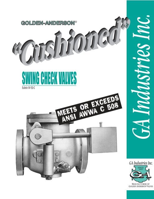
SWING CHECK VALVES<br />
Bulletin W-150-C<br />
MEETS OR EXCEEDS<br />
ANSI AWWA C 508
SWING CHECK<br />
VALVE. THE ONLY VALVE<br />
THAT PROVIDES ALL<br />
THESE FEATURES.<br />
Large cover access port easily allowing for<br />
maintenance and clean out<br />
Convex<br />
disc face<br />
creates<br />
increased<br />
lifting<br />
force, and<br />
decreases<br />
headloss.<br />
Full ported<br />
seat<br />
opening.<br />
The full-bodied long-radius mid section<br />
creates maximum flow less restriction.<br />
The body<br />
and disc are<br />
designed in a<br />
special<br />
configuration<br />
to minimize<br />
slam.<br />
1<br />
Optional metal to metal seat.<br />
Vertical Installation Horizontal Installation<br />
Note: Suffix “A” used after figure number for vertical<br />
installation (i.e. 250 DA)<br />
The Golden Advantage.<br />
Adjustable<br />
Weighted Arm<br />
Adjustable<br />
Cushion<br />
Chamber<br />
Suitable for Horizontal or Vertical Installation<br />
Optional: limit<br />
switch to send<br />
signals, etc.<br />
OPTIONAL: Rubber or Special Lining<br />
OPTIONAL: Access port on bottom of body for<br />
clean out. Available on all bodies.<br />
Single increase Double increase<br />
Available in increasing sizes larger than inlet.<br />
Saves space...economical...eliminates using<br />
an increaser. Other options adaptable.
SWING CHECK<br />
VALVE APPLICATIONS<br />
AND OPERATIONS<br />
Description<br />
The Fig.250-D is a counterweighted, rubber or metal<br />
seated check valve with attached cushion chamber<br />
whose function is to permit flow in only one direction,<br />
close tightly when its discharge side pressure exceeds<br />
its inlet pressure, and to close without a slam or bang.<br />
Installation<br />
The valve must be installed such that the inlet pressure<br />
enters the valve so as to open the main valve disc. The<br />
counterweight should be placed at the extreme end of<br />
the counterweight arm. The counterweight arm should<br />
be in a horizontal position. The cushion chamber<br />
adjusting sleeve should normally be about half way out.<br />
Operation<br />
When the pump starts, it should be observed if the<br />
counterweight arm moves fully open to a stop. If the<br />
counterweight arm does not reach a full open position,<br />
and appears to oscillate on the flow, this may encourage<br />
premature shaft bearing wear. Before trying to correct<br />
this by moving the counterweight inward, shut the<br />
pump down to observe any slamming tendency. If the<br />
valve closed quietly, the counterweight may be moved<br />
inward slightly to see if the valve will then open fully. If<br />
a slam is experienced, the weight must be moved<br />
outward. The valve is full ported when about 20 degrees<br />
open, so a 60 degree open position is not actually<br />
necessary. The extra opening is provided to offer<br />
minimum obstruction to high flow.<br />
Cushion Chamber 1<br />
A common check valve slams when its disc is caught<br />
in a partially open position when flow reversal occurs.<br />
So, it is essential that the counterweight closes the<br />
valve before a reversal occurs during the pump coast<br />
down phase. If a slam is experienced even though the<br />
weight is at the extreme end of the counterweight arm,<br />
additional weight may be required. The proper amount<br />
may be determined by placing one’s hand on the<br />
present counterweight and applying a slight force<br />
when the pump is shut down. A few tests will indicate<br />
the required amount of weight to be added.<br />
The cushion chamber cannot retard the valve closure<br />
during a flow reversal due to the tremendous forces<br />
involved. The cushion chamber will minimize a<br />
slamming tendency when the valve closes too quickly<br />
due to its own counterweight action by cushioning<br />
the last increment of movement just before the disc<br />
contacts the seat to close the valve. An inward<br />
adjustment of the bushing will increase this<br />
cushioning tendency.<br />
The below references cover the general list of materials for swing<br />
check valves. They are subject to change to make them conform to<br />
the specific requirements of the particular job for which they are<br />
required. The material specifications shown above shall conform to<br />
the most recently published standards.<br />
MATERIALS OF CONSTRUCTION<br />
PRINT MATERIAL ASTM or SAE<br />
Body, Cover, Disc, Cast Iron A 126 C1.B.<br />
Levers, Disc Arm or Cast Steel A 216 C1. WCB<br />
Seat Stainless Steel (to 12”) A 157-C9 (STD)<br />
Bronze (14” up) B62 (Standard)<br />
Seat Ring Rubber 80 Dur. (Rubber)<br />
Metal Bronze/Stainless Steel<br />
Cover Gasket Composition Garlock 660<br />
Hinge Shaft Stainless Steel Type 303 Commercial<br />
Studs, Bolts, Nuts Steel Commercial<br />
Cushion Chamber<br />
Assembly Bronze Trim B62<br />
Stuffing Box Packing Composition Garlock 234 or equal.<br />
1 Applies to sizes 2” thru 36”<br />
2
SWING CHECK<br />
VALVES DIMENSIONS<br />
& PARTS<br />
Note: Flanges per ANSI B16.1<br />
unless otherwise specified. Valve<br />
available with flanges to DIN, ISO<br />
BS Std. or special<br />
1. Body<br />
2. Body Seat<br />
2A. Seat O-Ring<br />
2B. Seat Pins<br />
3. Disc & Center Pin<br />
4. Disc Arm<br />
5A. Renewable Seat<br />
5B. Seat Follower<br />
5C. Seat Screws<br />
5D. Metal Seat Washer<br />
6. Disc Nut<br />
6A. Disc Nut Washer<br />
6B. Disc Nut Pin<br />
8. Cover Gasket<br />
9. Cover<br />
10. Cover Bolts<br />
11. Shaft<br />
12. Disc Arm Set Screws<br />
13. Inner Bushing<br />
14. Outer Bushing<br />
15. Gland<br />
16. Gland Studs<br />
17. Gland Packing<br />
18. Shaft Lock Pin<br />
LIST OF PARTS<br />
29. Disc Arm Key<br />
20. Cushion Chamber<br />
21. Chamber Screw<br />
22. Plunger<br />
23. Plunger-O-Ring<br />
26. Adjusting Sleeve<br />
27. Sleeve Lock Nut<br />
28. Link<br />
28A. Link Pin<br />
29. Lever<br />
29A. Lever Set Screw<br />
29B. Lever Pin<br />
We reserve the right to substitute parts of material which are of equal or superior quality.<br />
VALVE<br />
SIZE<br />
A<br />
B<br />
C<br />
D<br />
E<br />
Shipping<br />
Weight<br />
GENERAL DIMENSIONS Inches & Millimeters<br />
3<br />
Section showing optional valve<br />
with metal to metal seat. Seat<br />
and seat follower are one<br />
piece. (Optional at extra cost,<br />
consult factory.)<br />
29C. Lever Cotter Pin<br />
30. Counterweight ARM<br />
30A. CVVT Arm Set Screws<br />
30B. CWT Arm Key<br />
31. Counterweight<br />
31A. CWT Set Screw<br />
32. <strong>Check</strong> Valve<br />
33. Cover Plug<br />
34. Shaft End Plate<br />
35. End Plate Bolts<br />
36. End Plate Seal<br />
IN 2 21/2 3 4 6 8 10 12 14 16 18 20 24 30 36 42 48 54 60<br />
MM 50 63 76 101 152 203 254 304 355 406 457 508 609 762 914 1066 1219 1371 1524<br />
IN 12 12 12 13 171/2 18 23 28 33 36 40 40 48 60 63 70 76 102 114<br />
MM 305 305 305 330 445 457 584 711 838 914 1016 1016 1219 1524 1600 1778 1930 2590 2895<br />
IN 7 7 7 81/2 9 12 14 16 22 23 24 24 28 33 36 40 46 62 69<br />
MM 178 178 178 216 229 305 356 406 559 584 610 610 711 838 914 1016 1168 1574 1752<br />
IN 5 5 5 5 6 9 9 11 13 14 18 18 20 26 30 33 36 40 45<br />
MM 127 127 127 127 153 229 229 279 330 356 438 438 508 660 762 838 914 1016 1143<br />
IN 10 10 10 11 12 14 15 17 20 24 28 28 34 41 43 46 50 60 72<br />
MM 254 254 254 279 305 356 381 432 508 610 711 711 864 1041 1092 1168 1270 1524 1828<br />
IN 5 5 5 5 7 8 9 11 14 16 18 18 21 32 34 33 41 60 72<br />
MM 127 127 127 127 178 203 229 279 356 406 457 457 533 812 863 838 1041 1524 1828<br />
LBS 101 101 101 154 234 310 485 970 1480 1860 2400 2800 6000 8200 13500 14600 18000 20000 22000<br />
KG 46 46 46 70 106 140 220 440 671 844 1088 1270 2720 3720 6123 6621 8164 9077 9978
MAINTENANCE,<br />
SPECIFICATIONS AND<br />
HEAD LOSS<br />
Maintenance<br />
A reversal flow through the valve when the valve is in the<br />
closed position generally indicates a damaged or worn seat<br />
rubber. This can usually be detected by the sound of leaking<br />
water when the valve is closed.<br />
Any time the main valve is dismantled, it is recommended<br />
that the hinge shaft be polished smooth when the shaft<br />
passes through the gland packing. Upon reassembly do<br />
not exert excessive force on the gland screws as the<br />
packing can produce a considerable friction on the hinge<br />
shaft. All set screws should be checked for tightness.<br />
Specifications<br />
The swing check valve shall be constructed with heavy<br />
cast iron or cast steel body with a bronze or stainless<br />
steel seat ring, a non-corrosive shaft for attachment of<br />
weight and lever, and complete non-corrosive trim<br />
cushion chamber.<br />
It shall absolutely prevent the return of water, oil or gas<br />
back through the valve when the inlet pressure decreases<br />
below the delivery pressure. The valve must be tight<br />
seating, and must be cushioned in operation. The seat<br />
ring must be renewable.<br />
The cushion chamber shall be attached to the side of the<br />
valve body externally and so constructed with a piston<br />
operating in a chamber that will effectively permit the<br />
valve to be operated without any hammering action. The<br />
cushion chamber shall be arranged that the closing will<br />
be adjustable to meet the service requirements.<br />
The valve disc shall be convex and of cast iron or cast<br />
steel and shall be suspended from a non-corrosive shaft<br />
which will pass through a stuffing box and be connected<br />
to the cushion chamber on the outside of the valve.<br />
All material and workmanship shall be first class throughout<br />
and the purchaser reserves the right to inspect this<br />
valve before shipment.<br />
The valve will be the <strong>GA</strong> <strong>Industries</strong>, Inc. Fig. No. 250-D (for<br />
125# ANSI Std.) Fig. No. 250-U (for 250# ANSI Std.),<br />
Cranberry Twp., PA<br />
STANDARD FLANGE FIGURE NUMBERS<br />
250-D – Cast Iron – FF & D – 125# ANSI, 250-U – Cast Iron – FF&D – 250# ANSI, 250-V – Cast Steel – FF&D – 300# ANSI, 250-W – Cast Steel –<br />
FF&D – 400# ANSI. (For special flanges, consult the home office.)<br />
Test performed with valve full open<br />
We challenge any other manufacturer of check valves to prove by competitive tests a lower headloss.<br />
4<br />
FIG. 250-D<br />
FULL OPEN
Double<br />
Increasing<br />
also available<br />
Fig 252<br />
Consult Factory<br />
for Details<br />
SINGLE-<br />
SIZE CUSHIONED<br />
SWING CHECK<br />
VALVES<br />
Fig 251-D Single Increasing<br />
Description<br />
The Golden Anderson increasing size cushioned<br />
check valve has a one size larger outlet flange than<br />
the nominal valve size. This valve is particularly<br />
applicable for use on package sewage lift stations<br />
where space is at a premium and reduced coupling<br />
take valuable space.<br />
Specifications<br />
The increasing size check valve shall be constructed<br />
with heavy cast iron or cast steel body with a bronze or<br />
stainless steel seat ring, a non-corrosive shaft for<br />
attachment of weight and lever, and complete<br />
non-corrosive trim cushion chamber.<br />
It shall absolutely prevent the return of waste water, oil<br />
or gas back through the valve when the inlet pressure<br />
decreases below the delivery pressure. The valve must<br />
be tight seating and must operate without hammer or<br />
shock. The seat ring must be renewable.<br />
The cushion chamber shall be attached to the side of<br />
the valve body externally and so constructed with a<br />
piston operating in a chamber that will effectively permit<br />
the valve to be operated without any hammering action.<br />
The cushion chamber shall be so arranged that the final<br />
increment of closing will be adjustable to meet the<br />
service requirements.<br />
The valve disc shall be of cast iron or cast steel and<br />
shall be suspended from a non-corrosive shaft which<br />
will pass through a stuffing box and be connected to<br />
the cushion chamber on the outside of the valve.<br />
All material and workmanship shall be first class<br />
throughout and the purchaser reserves the right to<br />
inspect this valve before shipment.<br />
The valve will be the <strong>GA</strong> <strong>Industries</strong>__(size), Fig. 251-D.<br />
5<br />
Section showing<br />
alternate valve with<br />
metal to metal seat.<br />
Seat and seat follower<br />
are one piece.<br />
(Optional at extra cost.<br />
Consult factory.)<br />
NOTE: Smaller flange size is always the inlet; larger flange<br />
size is always the outlet. All flanges per ANSl B16.1.<br />
For larger sizes or optional equipment such as: position<br />
indicator, limit switch, rubber coatings, higher pressures,<br />
special materials, special flanges, etc., consult the factory.<br />
For materials of construction, see page 2.<br />
For head loss, see chart page 4.<br />
For operation and installation instructions, see page 2.<br />
For parts list, see page 3.<br />
GENERAL DIMENSIONS - Inches & Millimeters<br />
VALVE IN 3 X 4 4 X 6 6 X 8 8 X 10 10 X 12<br />
SIZE MM 76 X 101 101 X 152 152 X 203 203 X 254 254 X 304<br />
A<br />
IN<br />
MM<br />
12<br />
305<br />
13<br />
330<br />
17 1/2<br />
445<br />
18<br />
457<br />
23<br />
584<br />
B<br />
IN<br />
MM<br />
7<br />
178<br />
8 1/2<br />
216<br />
9<br />
229<br />
12<br />
305<br />
14<br />
356<br />
C<br />
IN<br />
MM<br />
5<br />
127<br />
6<br />
153<br />
7<br />
177<br />
9<br />
229<br />
9<br />
229<br />
D<br />
IN<br />
MM<br />
10<br />
254<br />
11<br />
279<br />
12<br />
305<br />
14<br />
356<br />
15<br />
381<br />
E<br />
IN<br />
MM<br />
5<br />
127<br />
5<br />
127<br />
7<br />
178<br />
8<br />
203<br />
9<br />
229<br />
Shipping LBS 120 175 250 350 525<br />
Weight<br />
KGS 54 79 113 158 238
POWER<br />
ASSISTED SWING<br />
CHECK VALVES<br />
Fig. Number 250-PASC<br />
Description<br />
The Power Assisted <strong>Swing</strong> <strong>Check</strong> Valve is designed to<br />
close more rapidly than can be accomplished with an<br />
ordinary spring or weight loaded check valve. It is<br />
especially designed for those very difficult applications<br />
where a pump with a low WR 2 exists, a flow condition<br />
not adequately protected by either weight loaded or<br />
spring loaded swing check valves, particularly when<br />
applied to larger sized valves.<br />
The purpose of the extra fast closure on this valve is to<br />
completely shut the valve before the forward flow of<br />
fluid stops. Hence the reversal of flow does not strike a<br />
partially open disc and create damaging hammer. The<br />
Pneumatic Power Assist Unit provides adjustable closing<br />
speed and adjustable closing force which enables this<br />
valve to be accurately set so that the disc comes into<br />
contact with the seat just prior to flow reversal, thus<br />
providing cushioned operation.<br />
Specifications<br />
The Power Assisted Closing <strong>Swing</strong> <strong>Check</strong> Valve shall<br />
be designed for extra fast closing so that the valve will<br />
be completely closed before the forward flow of fluid<br />
stops. It shall be of the <strong>Swing</strong> <strong>Check</strong> Lever and Weight<br />
Design with the hinge shaft axis out of the waterway,<br />
applicable for installation in a vertical upward flow or<br />
horizontal flow position. The valve shall be 100% full<br />
ported when open and provide droptight closure. A power<br />
assist cylinder shall be securely attached to the valve<br />
body to accomplish rapid, but adjustable speed of valve<br />
closure. An independent source of fluid at ______ PSI<br />
minimum shall be available as a power source for the<br />
cylinder, and there shall be provided a small pressure<br />
regulator on the power source line to regulate the uniform<br />
pressure to the power cylinder. Also, in the power line<br />
shall be a solenoid operated pilot which will be energized<br />
with pump start-up and when de-energized will direct flow<br />
from independent power source to the power cylinder to<br />
rapidly close the valve, such function being synchronized<br />
with pump coast down time. It shall be possible to field<br />
adjust the closing speed of the valve.<br />
The valve shall be constructed with cast iron body having<br />
a securely fastened bronze seat therein (or cast steel body<br />
with stainless steel seat). The disc shall be cast iron or<br />
GENERAL DIMENSIONS - Inches & Millimeters<br />
VALVE IN 16 18 20 24 30 36 42 48<br />
SIZE MM 406 457 508 609 762 914 1066 1219<br />
A<br />
IN<br />
MM<br />
36<br />
914<br />
40<br />
1016<br />
40<br />
1016<br />
48<br />
1219<br />
60<br />
1524<br />
63 70<br />
1600 1778<br />
76<br />
1930<br />
B<br />
IN<br />
MM<br />
41 42<br />
1041 1066<br />
42<br />
1066<br />
44<br />
1117<br />
51<br />
1295<br />
54 58<br />
1371 1474<br />
64<br />
1625<br />
C<br />
IN<br />
MM<br />
14<br />
356<br />
18<br />
438<br />
18<br />
438<br />
20<br />
508<br />
26<br />
660<br />
30<br />
762<br />
33<br />
838<br />
36<br />
914<br />
D<br />
IN<br />
MM<br />
26<br />
660<br />
30<br />
762<br />
30<br />
762<br />
32<br />
802<br />
36<br />
914<br />
42 49<br />
1066 1244<br />
54<br />
1371<br />
E<br />
IN<br />
MM<br />
20<br />
508<br />
24<br />
609<br />
26<br />
660<br />
30<br />
762<br />
34<br />
863<br />
42 46<br />
1066 1168<br />
48<br />
1219<br />
Shipping LBS 1900 2500 2900 6100 8300 13600 14600 18000<br />
Weight<br />
KGS 862 1134 1316 2766 3764 6168 6621 8164<br />
6<br />
3 WAY SOLENOID PILOT<br />
EXHAUST<br />
PRESSURE REGULATOR<br />
AIR SUPPLY INLET<br />
cast steel, suspended from a noncorrosive shaft<br />
passing through a stuffing box and attached to the<br />
power cylinder outside of the valve. All material and<br />
workmanship shall be first class and the purchaser<br />
reserves the right to inspect the valve at the supplier’s<br />
plant. The valve shall be flanged F&D per 125# ANSI.<br />
The valve shall be as manufactured by <strong>GA</strong> <strong>Industries</strong>,<br />
Inc., their Figure No. 250-PASC.<br />
Notes: Flanges Per ANSI B16.1, unless otherwise indicated<br />
on customer’s order. For dimensions on valves larger or<br />
smaller than shown, consult factory. For cut-away drawing,<br />
material specifications and parts refer to Page 2 & 3.
AT AIR FORCE GUIDED<br />
MISSILE CENTER CAPE<br />
KENNEDY, FLORIDA<br />
The giant guided missiles consume huge quantities<br />
of rocket fuel in building up sufficient ejection<br />
pressure for take-off. The heat generated and blasted<br />
to the launching pad is terrific, causing spalling<br />
and disintegration of the concrete<br />
surfaces. To minimize this<br />
deterioration, the pads are flooded<br />
by large jets of water under pressure<br />
through Golden-Anderson <strong>Valves</strong> to<br />
act as a coolant. Just prior to firing of<br />
the rocket, there is a demand for high<br />
quantities of cooling water for several<br />
minutes. Upon take-off, the demand<br />
suddenly drops to zero.<br />
This condition creates rapid pressure<br />
changes and surges in the feed lines.<br />
To overcome the terrific surge in the<br />
water lines, <strong>GA</strong> Surge Relief <strong>Valves</strong><br />
were installed. As soon as the<br />
pressure exceeds a pre-determined<br />
intensity, these <strong>GA</strong> valves automatically<br />
open to discharge the excess. When<br />
pressure returns to normal, the valves<br />
automatically close.<br />
WARRANTY <strong>GA</strong> <strong>Valves</strong> are made of the finest<br />
available suitable materials and precaution has<br />
been taken to assure premium quality workmanship<br />
consistent with established quality control. <strong>Valves</strong><br />
or parts which are proved faulty due to defective<br />
material or workmanship will be replaced free of<br />
charge F.O.B. our plant upon written presentation<br />
of such proof. This warranty shall not cover cost<br />
of installation or any charges related thereto, and<br />
it is valid for a period of one year from date<br />
of shipment.<br />
9025 MARSHALL ROAD<br />
CRANBERRY TOWNSHIP, PA 16066-3696 USA<br />
PHONE: (724) 776-1020 FAX: (724) 776-1254<br />
WEB SITE: www.gaindustries.com<br />
E-MAIL: ga@gaindustries.com<br />
U. S. CORPS OF<br />
ENGINEERS<br />
Fast opening and closing is a must, and these six<br />
16-inch <strong>Cushioned</strong> <strong>Swing</strong> <strong>Check</strong> <strong>Valves</strong> automatically<br />
open when the pump starts forcing the water through<br />
the lines at a peak rate of 30,000 gpm. As soon as<br />
the pump shuts off, these large <strong>GA</strong> valves<br />
automatically close—drop tight.<br />
OUR GUARANTEE<br />
We guarantee these valves to be made of first grade materials and<br />
workmanship. Should any valve fail to operate satisfactorily from<br />
lack of either or both of these factors, we will accept return of the<br />
valve F.O.B. our plant and refund the purchase price. Any part of the<br />
valve which fails due to poor quality within one year of shipment<br />
from our plant will be replaced without charge. This is not meant to<br />
include labor cost of installing the part in the valve.<br />
We reserve the right to substitute materials which, in our opinion,<br />
are of equal or superior quality, in the construction of any valve for<br />
a particular application.<br />
We recommended the <strong>Cushioned</strong> <strong>Swing</strong><br />
<strong>Check</strong> Valve for use on all pumps including<br />
Variable Speed or Frequency Drive Pumps.<br />
Automatically responds to varying pump output.<br />
Closes quickly and quietly on power outage or<br />
pump failure.<br />
Positively protect system against backflow.<br />
No outside power source required for operation.<br />
Member AWWA<br />
Member WPCF<br />
MEMBER<br />
Water & Wastewater Equipment<br />
Manufacturers Association, Inc.<br />
ESTABLISHED 1908<br />
Agents throughout the world, to serve you. See your local directory, or contact our home office.<br />
COMM 01/04 1500