Air Release Valves Air/Vacuum Valves Combination ... - GA Industries
Air Release Valves Air/Vacuum Valves Combination ... - GA Industries
Air Release Valves Air/Vacuum Valves Combination ... - GA Industries

You also want an ePaper? Increase the reach of your titles
YUMPU automatically turns print PDFs into web optimized ePapers that Google loves.
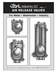
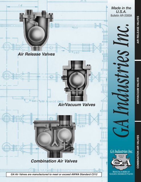
<strong>Air</strong> <strong>Release</strong> <strong>Valves</strong><br />
<strong>Air</strong>/<strong>Vacuum</strong> <strong>Valves</strong><br />
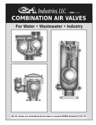
<strong>Combination</strong> <strong>Air</strong> <strong>Valves</strong><br />
<strong>GA</strong> <strong>Air</strong> <strong>Valves</strong> are manufactured to meet or exceed AWWA Standard C512<br />
Made in the<br />
U.S.A.<br />
Bulletin AR-2000A<br />
COMBINATION AIR VALVES AIR/VACUUM VALVES<br />
AIR RELEASE VALVES
AIR RELEASE VALVES AIR/VACUUM VALVES<br />
COMBINATION AIR VALVES<br />
AIR RELEASE VALVES<br />
For Water • Wastewater • Industry<br />
<strong>GA</strong> <strong>Air</strong> <strong>Valves</strong> are manufactured to meet or exceed AWWA Standard C512-92<br />
AIR & VACUUM VALVES<br />
& <strong>Vacuum</strong> Relief <strong>Valves</strong><br />
For Water • Wastewater • Industry<br />
<strong>GA</strong> <strong>Air</strong> <strong>Valves</strong> are manufactured to meet or exceed AWWA Standard C512-92<br />
COMBINATION AIR VALVES<br />
For Water • Wastewater • Industry<br />
<strong>GA</strong> <strong>Air</strong> <strong>Valves</strong> are manufactured to meet or exceed AWWA Standard C512-92<br />
INDEX<br />
AIR RELEASE VALVES Pages 2-17<br />
The Function of “<strong>Air</strong> <strong>Release</strong> <strong>Valves</strong>” is to automatically exhaust<br />
small amounts of air which collect at system high points once the<br />
system is filled and up to pressure. The orifice size generally varies<br />
between 1/16” and 3/8” depending on valve design and working<br />
pressure, although we can provide orifice of 1”, or larger size for<br />
special needs.<br />
In Operation, as small quantities of air bubbles enter the valve,<br />
they will displace the liquid within the valve and lower its level in<br />
relation to the float. When the level of the liquid is lowered to where<br />
the float is no longer buoyant, the float will drop. This motion opens<br />
the valve seat and permits the air which has accumulated in the<br />
upper portions of the valve body to be exhausted to atmosphere.<br />
When this air is released the liquid level in the valve once again<br />
rises, lifts the float and closes the valve seat. This cycle automatically<br />
repeats as often as necessary.<br />
AIR/VACUUM VALVES Pages 18-37<br />
The Function of “<strong>Air</strong>/<strong>Vacuum</strong> <strong>Valves</strong>” is to automatically exhaust<br />
large volumes of air from the system when it is being filled and also<br />
to allow air to re-enter the pipe line when being emptied. The orifice<br />
size is generally the same size as the valve inlet and outlet.<br />
In Operation when the system is filled, the fluid lifts the float until<br />
it closes the orifice. The orifice will remain closed until the system is<br />
emptied. <strong>Air</strong> may enter the valve and displace the fluid while the<br />
system is in operation, however, internal pressure will continue to<br />
hold the valve closed. The valve will not re-open until the system<br />
pressure drops to near atmospheric pressure and the float is no<br />
longer buoyed.<br />
COMBINATION AIR VALVES Pages 38-61<br />
The Function of “<strong>Combination</strong> <strong>Air</strong> <strong>Valves</strong>” is to automatically<br />
exhaust large volumes of air from the system when it is being filled<br />
and to allow air to re-enter the pipe on line break or when the<br />
system is being drained. Plus, <strong>Combination</strong> <strong>Air</strong> <strong>Valves</strong> automatically<br />
expel small amounts of air which collect at system high points once<br />
the system is filled up to pressure and fluid is flowing. YOU MIGHT<br />
SAY THAT COMBINATION AIR VALVES DO IT ALL.
AIR RELEASE VALVES<br />
For Water • Wastewater • Industry<br />
<strong>GA</strong> <strong>Air</strong> <strong>Valves</strong> are manufactured to meet or exceed AWWA Standard C512-92
AIR RELEASE VALVES<br />
Why Use <strong>Air</strong> <strong>Release</strong> <strong>Valves</strong>?<br />
<strong>Air</strong> that is entrained in a flowing liquid will naturally rise and<br />
tend to collect at high points within the system. This accumulation<br />
of air adds resistance to the liquid flow and can, under<br />
certain conditions, completely block the flow. However, the<br />
most common phenomenon is increased line resistance,<br />
requiring the pump to work harder, resulting in an increased<br />
energy consumption. Such a situation can continue unnoticed<br />
for a long time adding to the cost of operation.<br />
What Do They Do?<br />
<strong>Air</strong> <strong>Release</strong> <strong>Valves</strong> automatically exhaust these small amounts<br />
of air which collect at system high points, while the system is<br />
flowing and under pressure. This ensures the system will<br />
remain free of trapped air pockets, thereby increasing the efficiency<br />
and decreasing the overall operating cost of the system.<br />
How Do They Work?<br />
In operation, these valves are installed at high points in the<br />
system where air would naturally tend to collect. <strong>Air</strong> bubbles<br />
entering the valve will displace the liquid within the valve and<br />
lower the liquid level. When the level drops to where it no<br />
longer buoys the float, the float drops. This motion pulls the<br />
seat away from the orifice, opening the valve and allows the<br />
air that has accumulated in the upper portion of the valve to<br />
be exhausted to atmosphere. As the air is exhausted, liquid<br />
re-enters the valve, once again buoying the float, lifting it until<br />
the seat presses against the orifice, closing the valve. This<br />
cycle automatically repeats as often as necessary to maintain<br />
an air free system.<br />
Where Are They Used?<br />
<strong>Air</strong> <strong>Release</strong> <strong>Valves</strong> are installed on water transmission lines<br />
and sewage force mains, at or slightly downstream of peaks<br />
and high points, often as part of a “<strong>Combination</strong> <strong>Air</strong> Valve”<br />
(See Pages 38-61).<br />
Options & Accessories<br />
Flushing Attachment - Recommended with all sewage<br />
service air release valves, especially when used on<br />
raw sewage. Used to allow back-flushing of air release<br />
valve; includes isolating valves, quick-connect couplings<br />
and five feet of rubber hose.<br />
<strong>Vacuum</strong> Check - Used on outlet of air release valve to allow<br />
air to be vented from system but prevent re-entry of air<br />
when and if vacuum forms in the system.<br />
Isolating Valve - Supplied with air release valve to isolate<br />
valve from system for inspection or repair. Installed<br />
between valve and pipeline/system; 3” and smaller, ball<br />
valve is supplied, 4” and larger, butterfly valve is supplied.<br />
IMPORTANT NOTE: <strong>Air</strong> <strong>Release</strong> <strong>Valves</strong> cannot normally<br />
provide substantial vacuum protection when used alone.<br />
When vacuum protection is necessary, use in conjunction<br />
with adequate air/vacuum valves.<br />
AIR RELEASE VALVES...<br />
STANDARD CAPACITY<br />
Figure 901/902<br />
REFER TO PAGE 5 FOR DETAILS.<br />
Figure 905<br />
Figure 910/912<br />
Figure 901 Small Orifice <strong>Air</strong><br />
<strong>Release</strong> <strong>Valves</strong> have a 1/16”<br />
diameter orifice standard and are<br />
suitable for use up to 150 psi<br />
working pressure. For operating<br />
pressures to 50 psi, an optional<br />
3/32” diameter orifice is available.<br />
Figure 902 is similar to the Figure<br />
901, but utilizes a larger float for<br />
operation to 300 psi with standard<br />
1/16” diameter orifice. Standard<br />
inlet connection is 1” NPT.<br />
Figure 905, “Mini-Matic” is a<br />
small, compact, economical air<br />
release valve, suitable for use up<br />
to 200 psi WOG working pressure,<br />
in its standard construction.<br />
It has a relatively large (3/32”)<br />
standard orifice (150 psi max<br />
W.P.) to minimize plugging and a<br />
Buna-N seat, rendering it suitable<br />
for both hot (up to 180<br />
REFER TO PAGE 6 FOR DETAILS.<br />
o F) and<br />
cold water applications. The 905<br />
is available in 1/2” NPT or 3/4”<br />
NPT and can vent the trapped air<br />
from systems flowing up to 5,500<br />
GPM at a working pressure of<br />
150 PSI.<br />
Figure 912 <strong>Air</strong> <strong>Release</strong> Valve is<br />
slightly bigger than the 905 and<br />
has a larger standard orifice (1/8”<br />
dia.), to exhaust small pockets of<br />
air in systems flowing up to 9800<br />
GPM, at a working pressure of<br />
150 psig (300 psi, optional). The<br />
912 has a Buna-N seat (standard)<br />
and Viton is available as an<br />
option, with either 1/2”, 3/4” or 1”<br />
NPT inlet. Figure 910 is similar to<br />
the Figure 912 but has a 3/32”<br />
dia. orifice and is also available<br />
with 1/2”, 3/4” or 1” NPT inlet.<br />
REFER TO PAGE 7 FOR FIG. 910 DETAILS.<br />
REFER TO PAGE 8 FOR FIG. 912 DETAILS.<br />
Page 3 A Product of <strong>GA</strong> <strong>Industries</strong>
For Water, Wastewater and Raw Sewage<br />
HIGH CAPACITY SEWAGE SERVICE<br />
Figure 920 Figure 925<br />
REFER TO PAGE 9 FOR DETAILS.<br />
Figure 922<br />
REFER TO PAGE 10 FOR DETAILS.<br />
Figure 923<br />
REFER TO PAGE 11 FOR DETAILS.<br />
Figure 920 Compound Lever<br />
<strong>Air</strong> <strong>Release</strong> Valve has a 3/16”<br />
standard orifice, is available<br />
with 1” or 2” NPT inlet connections<br />
(1-1/2” NPT optional) and<br />
can exhaust residual air from<br />
systems flowing up to 22,000<br />
GPM at 150 psi working pressure.<br />
Optional orifices for lower<br />
(75 psi) or higher (300 psi)<br />
working pressure are available.<br />
A Buna-N seat is standard, but<br />
Viton is optional.<br />
Figure 922 High Capacity <strong>Air</strong><br />
<strong>Release</strong> <strong>Valves</strong> exhaust pockets<br />
of trapped air in high volume<br />
systems, or where excessive<br />
amounts of air are being<br />
introduced into the system. The<br />
large 3/8” orifice vents up to 235<br />
SCFM of air from systems<br />
flowing up to 88,000 GPM at a<br />
working pressure of 150 psi<br />
(standard). Standard inlet is<br />
either 2” or 3” NPT and optional<br />
orifices are available for higher<br />
(300 psi) or lower (75 psi)<br />
working pressure.<br />
Figure 923 Super High<br />
Capacity <strong>Air</strong> <strong>Release</strong> <strong>Valves</strong><br />
are used on very large diameter<br />
pipelines and/or systems<br />
that trap huge amounts of<br />
air. Its super-large orifice (up<br />
to 1” in diameter) can<br />
exhaust up to 1669 SCFM<br />
UNDER PRESSURE, up to<br />
150 psi, 6” inlet size.<br />
Optional orifices for operating<br />
pressures to 300 psi are<br />
available.<br />
REFER TO PAGE 12 FOR DETAILS.<br />
Figure 927<br />
REFER TO PAGE 13 FOR DETAILS.<br />
Figure 929<br />
REFER TO PAGE 14 FOR DETAILS.<br />
Figure 925 Standard Sewage <strong>Air</strong><br />
<strong>Release</strong> <strong>Valves</strong> exhaust air and<br />
sewage gas from pressurized<br />
sewage systems (force mains). The<br />
tall body minimizes the possibility<br />
of sewage plugging the orifice or<br />
causing the mechanism to stick.<br />
Standard 3/16” orifice vents air/gas<br />
from sewage systems flowing up to<br />
8,800 GPM at a working pressure<br />
of 150 psi. For lower pressure<br />
systems, an optional 5/16” orifice<br />
will vent 50% faster at pressures<br />
to 75 psi. Standard inlet is 2” NP.<br />
Figure 927 High Capacity Sewage<br />
<strong>Air</strong> <strong>Release</strong> <strong>Valves</strong> are recommended<br />
on high flow sewage systems<br />
(up to 47,900 GPM), where<br />
excessive air is being entrained<br />
and trapped or on systems that<br />
give off extraordinary amounts of<br />
sewage gas. The large 7/16” orifice<br />
vents up to 320 SCFM of air<br />
or gas at a working pressure of<br />
150 psi. For lower pressure systems,<br />
optional 1/2” orifice vents<br />
almost 31% faster at pressures up<br />
to 75 psi. Standard inlet is 2” NPT;<br />
3” NPT and 4” FLG optional.<br />
Figure 929 Short Body Sewage<br />
<strong>Air</strong> <strong>Release</strong> <strong>Valves</strong> are recommended<br />
ONLY when the depth of<br />
the trench will not permit a standard<br />
air release valve to be used.<br />
The short body valve is only 12”<br />
tall (vs. 20-1/2” for standard<br />
valve), but otherwise has all the<br />
features of the standard valve.<br />
Note: High capacity valve cannot<br />
be supplied in short body.<br />
A Product of <strong>GA</strong> <strong>Industries</strong> Page 4<br />
AIR RELEASE VALVES
AIR RELEASE VALVES<br />
SMALL ORIFICE<br />
<strong>Air</strong> <strong>Release</strong> <strong>Valves</strong><br />
AIR RELEASE VALVE<br />
FIG. 901/902<br />
GENERAL DIMENSIONS<br />
FIG.NO. INLET OUTLET A B WEIGHT<br />
(NPT) (DIAMETER) (SQUARE) (HEIGHT) (LBS.)<br />
901 1” 1/8” 5-3/8” 7-1/2” 23<br />
902 1” 1/8” 9” 11-3/8” 80<br />
ENGINEERING SPECIFICATION<br />
The <strong>Air</strong> <strong>Release</strong> Valve shall maintain closed position to<br />
prevent the loss of water by the positive seating of a noncorrosive<br />
float button against a smooth contact surface of<br />
the exhaust orifice. It shall automatically provide for the<br />
escape of air to atmosphere, without the loss of water,<br />
when the special ball float moves away from the orifice<br />
seat. The float shall be free floating within the valve body.<br />
Linkages of levers attached to the float are not acceptable.<br />
The body of the valve shall be of cast iron.<br />
The <strong>Air</strong> <strong>Release</strong> <strong>Valves</strong> shall be as manufactured by<br />
<strong>GA</strong> <strong>Industries</strong>, Inc., their Figure 901 (formerly Figure<br />
GH-4-150) or Figure 902 (formerly Figure GH-4-300).<br />
PARTS LIST<br />
1. BODY - Cast Iron A126 Class B<br />
2. COVER - Cast Iron A126 Class B<br />
3. ORIFICE - Delrin<br />
4. VENT PLUG - Delrin<br />
5. O-RING - Buna-N<br />
6. COVER BOLTS - Steel Grade 2<br />
7. COVER NUTS - Steel Grade 2<br />
8. FLOAT BALL - 316 Stainless Steel<br />
9. PATCH - Silicone Rubber<br />
ENGINEERING DATA<br />
Pressure Rating:<br />
Valve body rated 300 psi WOG,<br />
tested to 450 psi.<br />
Ball float tested to 1000 psi.<br />
FIG. 901/902<br />
Working Pressure:<br />
10-150 psi with 1/16” orifice (Standard-Fig. 901)<br />
10-150 psi with 3/32” orifice (Optional-Fig. 902-L)<br />
10-300 psi with 1/16” orifice (Standard-Fig. 902)<br />
CONSULT FACTORY IF OPERATING<br />
PRESSURE IS LESS THAN 10 PSI.<br />
Maximum Venting Rate:<br />
Fig. 901 @ 150 psi with 1/16” orifice =<br />
6.5 SCFM<br />
Fig. 902 @ 300 psi with 1/16” orifice =<br />
12.5 SCFM<br />
Fig.902-L @ 150 psi with 3/32” orifice =<br />
14.7 SCFM<br />
FOR SIZING AND LOCATING SEE PAGES<br />
16-17. OTHER ORIFICES AVAILABLE;<br />
CONSULT FACTORY.<br />
Where to Install <strong>Air</strong> <strong>Valves</strong>:<br />
1. Peaks<br />
2. Increased Down Slope<br />
3. Decrease in Upward Slope<br />
4. Long Ascents<br />
5. Long Descents<br />
6. Long Horizontals<br />
7. Pumps<br />
8. Large <strong>Valves</strong>, Cylinders and Piping Loops<br />
Page 5 A Product of <strong>GA</strong> <strong>Industries</strong>
MINI-MATIC<br />
Pressure Type <strong>Air</strong> Vent<br />
MINI-MATIC<br />
FIG. 905<br />
GENERAL DIMENSIONS<br />
VALVE VALVE A B C WEIGHT<br />
(INLET) (OUTLET) (LENGTH) (HEIGHT) (WIDTH) (LBS.)<br />
1/2” NPT<br />
3/4” NPT<br />
1” NPT<br />
1/4” NPT 4” 5-1/8” 3-3/8” 5<br />
ENGINEERING SPECIFICATION<br />
The <strong>Air</strong> Vent (<strong>Release</strong>) Valve shall be float operated and shall<br />
incorporate a simple lever mechanism to enable the valve to<br />
automatically release accumulated air from a fluid system while<br />
that system is pressurized and operating.<br />
The <strong>Air</strong> Vent Valve shall close drop tight, incorporating an<br />
easily renewable Buna-N seat, suitable for hot or cold steel. All<br />
internal metal parts shall be of stainless steel. The float shall be<br />
of stainless steel and be capable of withstanding a test pressure<br />
of 1000 PSIG. The linkage/lever mechanism shall be designed to<br />
prevent jamming.<br />
The body and cover shall be of cast iron conforming to<br />
ASTM A126 Class B, and shall be designed to withstand a test<br />
pressure of 300 PSIG.<br />
The <strong>Air</strong> Vent (<strong>Release</strong>) <strong>Valves</strong> shall be as manufactured by<br />
<strong>GA</strong> <strong>Industries</strong>, Inc., their Figure 905 Minimatic.<br />
PARTS LIST<br />
ENGINEERING DATA<br />
Pressure Rating:<br />
Valve body rated 200 psi WOG,<br />
tested to 300 psi.<br />
Float tested to 1000 psi.<br />
Working Pressure:<br />
10-150 psi with 3/32” orifice<br />
(Standard-Fig. 905)<br />
10-200 psi with 1/16” orifice<br />
(Optional-Fig. 905-H)<br />
CONSULT FACTORY IF OPERATING<br />
PRESSURE IS LESS THAN 10 PSI.<br />
FIG. 905<br />
1. BODY - Cast Iron A126 Class B<br />
2. COVER - Cast Iron A126 Class B<br />
3. <strong>GA</strong>SKET - Composition<br />
4. ORIFICE - 316 Stainless Steel<br />
5. FLOAT ARM - 316 Stainless Steel<br />
6. LEVERAGE BRACKET - 316 Stainless Steel<br />
7. ORIFICE BUTTON - Buna-N<br />
8. SPRING PIN - 410/420 Stainless Steel<br />
9. FLOAT BALL - 316 Stainless Steel<br />
10. CAP SCREW - 18-8 Stainless Steel<br />
11. LOCKWASHER - 18-8 Stainless Steel<br />
12. PIPE PLUG 1/2” NPT - Steel (Commercial)<br />
13. COVER BOLTS - Steel Grade 2<br />
14. COILED SPRING PIN - 302 Stainless Steel<br />
15. BUSHING - Steel (Commercial)<br />
16. PIPE PLUG 1/4” NPT - Steel (Commercial)<br />
Maximum Venting Rate:<br />
Fig. 905 @ 150 psi with 3/32” orifice =<br />
14.7 SCFM<br />
Fig. 905-H @ 200 psi with 1/16” orifice =<br />
8.5 SCFM<br />
FOR SIZING AND LOCATING SEE PAGES<br />
16-17. OTHER ORIFICES AVAILABLE;<br />
CONSULT FACTORY.<br />
Where to Install <strong>Air</strong> <strong>Valves</strong>:<br />
1. Peaks<br />
2. Increased Down Slope<br />
3. Decrease in Upward Slope<br />
4. Long Ascents<br />
5. Long Descents<br />
6. Long Horizontals<br />
7. Pumps<br />
8. Large <strong>Valves</strong>, Cylinders and Piping Loops<br />
A Product of <strong>GA</strong> <strong>Industries</strong> Page 6<br />
AIR RELEASE VALVES
AIR RELEASE VALVES<br />
SIMPLE LEVER<br />
Pressure Type <strong>Air</strong> <strong>Release</strong> Valve<br />
SIMPLE LEVER AIR RELEASE<br />
FIG. 910<br />
GENERAL DIMENSIONS<br />
VALVE VALVE A B WEIGHT<br />
(INLET) (OUTLET) (DIAMETER) (HEIGHT) (LBS.)<br />
1/2” NPT<br />
3/4” NPT<br />
1” NPT<br />
3/8” NPT 5-1/8” 6-1/4” 8<br />
ENGINEERING SPECIFICATION<br />
15<br />
When<br />
Required<br />
The <strong>Air</strong> <strong>Release</strong> Valve shall be float operated and shall<br />
incorporate a simple lever mechanism to enable the valve to<br />
automatically release accumulated air from a fluid system while<br />
that system is pressurized and operating.<br />
The <strong>Air</strong> <strong>Release</strong> Valve shall close drop tight, incorporating an<br />
easily renewable Buna-N seat for superior service on water. All<br />
internal metal parts shall be of stainless steel. The float shall be<br />
of stainless steel and be capable of withstanding a test pressure<br />
of 1000 PSIG. The linkage/lever mechanism shall be designed<br />
to prevent jamming.<br />
The body and cover shall be of cast iron conforming to<br />
ASTM A126 Class B, and shall be designed to withstand a<br />
test pressure of 450 PSIG.<br />
The <strong>Air</strong> <strong>Release</strong> <strong>Valves</strong> shall be as manufactured by<br />
<strong>GA</strong> <strong>Industries</strong>, Inc., their Figure 910 (formerly Figure 1/2-AR,<br />
3/4-AR and 1 AR).<br />
PARTS LIST<br />
ENGINEERING DATA<br />
Pressure Rating:<br />
Valve body rated 300 psi WOG,<br />
tested to 450 psi.<br />
Float tested to 1000 psi.<br />
Working Pressure:<br />
10-150 psi with 3/32” orifice<br />
(Standard-Fig. 910)<br />
10-300 psi with 1/16” orifice<br />
(Optional-Fig. 910-H)<br />
CONSULT FACTORY IF OPERATING<br />
PRESSURE IS LESS THAN 10 PSI.<br />
FIG. 910<br />
1. BODY - Cast Iron A126 Class B<br />
2. COVER - Cast Iron A126 Class B<br />
3. LEVERAGE BRACKET - 316 Stainless Steel<br />
4. ORIFICE - 316 Stainless Steel<br />
5. FLOAT ARM - 316 Stainless Steel<br />
6. <strong>GA</strong>SKET - Composition<br />
7. COVER BOLTS - Steel Grade 2<br />
8. BRACKET SCREW - 18-8 Stainless Steel<br />
9. FLOAT ARM - 316 Stainless Steel<br />
10. ORIFICE BUTTON - Buna-N<br />
11. COILED SPRING PIN - 302 Stainless Steel<br />
12. FLOAT SCREW - 18-8 Stainless Steel<br />
13. LOCKWASHER - 18-8 Stainless Steel<br />
14. PIPE PLUG - Steel (Commercial)<br />
15. REDUCING BUSHING - Steel (Commercial)<br />
Maximum Venting Rate:<br />
Fig. 910 @ 150 psi with 3/32” orifice =<br />
14.7 SCFM<br />
Fig. 910-H @ 300 psi with 1/16” orifice =<br />
12.5 SCFM<br />
FOR SIZING AND LOCATING SEE PAGES<br />
16-17. OTHER ORIFICES AVAILABLE;<br />
CONSULT FACTORY.<br />
Where to Install <strong>Air</strong> <strong>Valves</strong>:<br />
1. Peaks<br />
2. Increased Down Slope<br />
3. Decrease in Upward Slope<br />
4. Long Ascents<br />
5. Long Descents<br />
6. Long Horizontals<br />
7. Pumps<br />
8. Large <strong>Valves</strong>, Cylinders and Piping Loops<br />
Page 7 A Product of <strong>GA</strong> <strong>Industries</strong>
SIMPLE LEVER<br />
Pressure Type <strong>Air</strong> <strong>Release</strong><br />
Valve FIG. 912<br />
SIMPLE LEVER AIR RELEASE<br />
FIG. 912<br />
GENERAL DIMENSIONS<br />
VALVE VALVE A B WEIGHT<br />
(INLET) (OUTLET) (DIAMETER) (HEIGHT) (LBS.)<br />
1/2” NPT<br />
3/4” NPT<br />
1” NPT<br />
3/8” NPT 5-1/8” 6-1/4” 8<br />
ENGINEERING SPECIFICATION<br />
The <strong>Air</strong> <strong>Release</strong> Valve shall be float operated and shall<br />
incorporate a simple lever mechanism to enable the valve to<br />
automatically release accumulated air from a fluid system while<br />
that system is pressurized and operating.<br />
The <strong>Air</strong> <strong>Release</strong> Valve shall close drop tight, incorporating a<br />
renewable Buna-N seat for superior service on water. All internal<br />
metal parts shall be of stainless steel, withstanding a test pressure<br />
of 1000 PSIG. The linkage/lever mechanism shall be<br />
designed to prevent jamming.<br />
The body and cover shall be of cast iron conforming to<br />
ASTM A126 Class B, and shall be designed to withstand a<br />
test pressure of 450 PSIG.<br />
The <strong>Air</strong> <strong>Release</strong> <strong>Valves</strong> shall be as manufactured by<br />
<strong>GA</strong> <strong>Industries</strong>, Inc., their Figure 912.<br />
PARTS LIST<br />
1. BODY - Cast Iron A126 Class B<br />
2. COVER - Cast Iron A126 Class B<br />
3. LEVERAGE BRACKET - 316 Stainless Steel<br />
4. ORIFICE - 316 Stainless Steel<br />
5. FLOAT BALL - 316 Stainless Steel<br />
6. <strong>GA</strong>SKET - Composition<br />
7. COVER BOLTS - Steel Grade 2<br />
8. BRACKET SCREW - 316 Stainless Steel<br />
9. FLOAT ARM - 316 Stainless Steel<br />
10. ORIFICE BUTTON - Buna-N<br />
11. COILED SPRING PIN - 302 Stainless Steel<br />
12. PIVOT LINK - 316 Stainless Steel<br />
13. FLOAT SCREW - 18-8 Stainless Steel<br />
14. LOCKWASHER - 18-8 Stainless Steel<br />
15. PIPE PLUG - Steel (Commercial)<br />
16. REDUCING BUSHING - Steel (Commercial)<br />
ENGINEERING DATA<br />
Pressure Rating:<br />
Valve body rated 300 psi WOG,<br />
tested to 450 psi.<br />
Float tested to 1000 psi.<br />
Working Pressure:<br />
10-150 psi with 1/8” orifice<br />
(Standard-Fig. 912)<br />
10-300 psi with 3/32” orifice<br />
(Optional-Fig. 912-H)<br />
CONSULT FACTORY IF OPERATING<br />
PRESSURE IS LESS THAN 10 PSI.<br />
Maximum Venting Rate:<br />
Fig. 912 @ 150 psi with 1/8” orifice =<br />
26.1 SCFM<br />
Fig. 912-H @ 300 psi with 3/32” orifice =<br />
28 SCFM<br />
FOR SIZING AND LOCATING SEE PAGES<br />
16-17. OTHER ORIFICES AVAILABLE;<br />
CONSULT FACTORY.<br />
Where to Install <strong>Air</strong> <strong>Valves</strong>:<br />
1. Peaks<br />
2. Increased Down Slope<br />
3. Decrease in Upward Slope<br />
4. Long Ascents<br />
5. Long Descents<br />
6. Long Horizontals<br />
7. Pumps<br />
8. Large <strong>Valves</strong>, Cylinders and Piping Loops<br />
A Product of <strong>GA</strong> <strong>Industries</strong> Page 8<br />
AIR RELEASE VALVES
AIR RELEASE VALVES<br />
COMPOUND LEVER<br />
Pressure Type <strong>Air</strong> <strong>Release</strong> Valve<br />
COMPOUND LEVER AIR RELEASE<br />
FIG. 920<br />
GENERAL DIMENSIONS<br />
VALVE VALVE A B WEIGHT<br />
(INLET) (OUTLET) (SQUARE) (HEIGHT) (LBS.)<br />
1” NPT<br />
1-1/2” NPT<br />
2” NPT<br />
1/2” NPT 6-3/8” 9-7/8” 24<br />
ENGINEERING SPECIFICATION<br />
The <strong>Air</strong> <strong>Release</strong> Valve shall be float operated and shall<br />
incorporate a compound lever mechanism to enable the valve to<br />
automatically release accumulated air from a fluid system while<br />
that system is pressurized and operating.<br />
The <strong>Air</strong> <strong>Release</strong> Valve shall close drop tight, incorporating an<br />
adjustable Buna-N orifice button. All internal metal parts shall be<br />
of stainless steel. The float shall be of stainless steel and be<br />
capable of withstanding a test pressure of 1000 PSIG. The linkage/lever<br />
mechanism shall be able to be removed from the valve<br />
without disassembly of the mechanism, and shall be designed to<br />
prevent jamming.<br />
The body and cover shall be of cast iron conforming to<br />
ASTM A126 Class B, and shall be designed to withstand a<br />
test pressure of 450 PSIG.<br />
The <strong>Air</strong> <strong>Release</strong> <strong>Valves</strong> shall be as manufactured by<br />
<strong>GA</strong> <strong>Industries</strong>, Inc., their Figure 920 (formerly Figure 1-AR,<br />
A 1/2-AR and 2-AR).<br />
PARTS LIST<br />
ENGINEERING DATA<br />
Pressure Rating:<br />
Valve body rated 300 psi WOG,<br />
tested to 450 psi.<br />
Float tested to 1000 psi.<br />
Working Pressure:<br />
10-150 psi with 3/16” orifice<br />
(Standard-Fig. 920)<br />
10-300 psi with 1/8” orifice<br />
(Optional-Fig. 920-H)<br />
CONSULT FACTORY IF OPERATING<br />
PRESSURE IS LESS THAN 10 PSI.<br />
FIG. 920<br />
1. BODY - Cast Iron A126 Class B<br />
2. COVER - Cast Iron A126 Class B<br />
3. LEVERAGE BRACKET - 316 Stainless Steel<br />
4. BRACKET SCREW - 18-8 Stainless Steel<br />
5. LEVER ARM - 316 Stainless Steel<br />
6. FLOAT ARM - 316 Stainless Steel<br />
7. ORIFICE BUTTON - Buna-N/18-8 Stainless Steel<br />
8. HEX NUT - 18-8 Stainless Steel<br />
9. LOCKWASHER - 18-8 Stainless Steel<br />
10. COILED SPRING PIN - 302 Stainless Steel<br />
11. VALVE LINK (<strong>Air</strong> <strong>Release</strong>) - 316 Stainless Steel<br />
12. PIVOT LINK - 316 Stainless Steel<br />
13. FLOAT CAP SCREW - 18-8 Stainless Steel<br />
14. BRACKET LOCKWASHER - 18-8 Stainless Steel<br />
15. FLOAT BALL - 316 Stainless Steel<br />
16. COVER BOLTS - Steel Grade 2<br />
17. COVER NUTS - Steel Grade 2<br />
18. PIPE PLUG 1/2” NPT - Steel (Commercial)<br />
19. PIPE PLUG 1” NPT - Malleable Iron<br />
20. ORIFICE - 316 Stainless Steel<br />
21. O-RING - Buna-N<br />
Maximum Venting Rate:<br />
Fig. 920 @ 150 psi with 3/16” orifice =<br />
58.7 SCFM<br />
Fig. 920-H @ 300 psi with 1/8” orifice =<br />
49.8 SCFM<br />
FOR SIZING AND LOCATING SEE PAGES<br />
16-17. OTHER ORIFICES AVAILABLE;<br />
CONSULT FACTORY.<br />
Where to Install <strong>Air</strong> <strong>Valves</strong>:<br />
1. Peaks<br />
2. Increased Down Slope<br />
3. Decrease in Upward Slope<br />
4. Long Ascents<br />
5. Long Descents<br />
6. Long Horizontals<br />
7. Pumps<br />
8. Large <strong>Valves</strong>, Cylinders and Piping Loops<br />
Page 9 A Product of <strong>GA</strong> <strong>Industries</strong>
HIGH CAPACITY<br />
COMPOUND LEVER<br />
Pressure Type <strong>Air</strong> <strong>Release</strong> Valve FIG. 922<br />
HI-CAPACITY AIR RELEASE PARTS LIST<br />
GENERAL DIMENSIONS<br />
FIG. 922<br />
VALVE VALVE A B WEIGHT<br />
(INLET) (OUTLET) (SQUARE) (HEIGHT) (LBS.)<br />
2” NPT<br />
3” NPT<br />
1/2” NPT 6-3/8” 12” 40<br />
ENGINEERING SPECIFICATION<br />
The <strong>Air</strong> <strong>Release</strong> Valve shall be float operated and shall<br />
incorporate a compound lever mechanism to enable the valve to<br />
automatically release accumulated air from a fluid system while<br />
that system is pressurized and operating.<br />
The <strong>Air</strong> <strong>Release</strong> Valve shall close drop tight, incorporating an<br />
adjustable Buna-N orifice button. All internal metal parts shall be<br />
capable of withstanding a test pressure of 1000 PSIG. The<br />
linkage/lever mechanism shall be able to be removed from the<br />
valve without disassembly of the mechanism, and shall be<br />
designed to prevent jamming.<br />
The body and cover shall be of cast iron conforming to<br />
ASTM A126 Class B, and shall be designed to withstand a<br />
test pressure of 450 PSIG.<br />
The <strong>Air</strong> <strong>Release</strong> <strong>Valves</strong> shall be as manufactured by<br />
<strong>GA</strong> <strong>Industries</strong>, Inc., their Figure 922 (formerly Figure 2-LAR<br />
and 3-LAR).<br />
1. BODY - Cast Iron A126 Class B<br />
2. COVER - Cast Iron A126 Class B<br />
3. LEVERAGE BRACKET - 316 Stainless Steel<br />
4. ORIFICE - 316 Stainless Steel<br />
5. BRACKET CAP SCREWS - 18-8 Stainless Steel<br />
6. BRACKET LOCKWASHERS - 18-8 Stainless Steel<br />
7. ORIFICE BUTTON - 18-8 Stainless Steel<br />
8. HEX NUT - 18-8 Stainless Steel<br />
9. LOCKWASHER - 18-8 Stainless Steel<br />
10. O-RING - Buna-N<br />
11. LEVERAGE ARM - 316 Stainless Steel<br />
12. FLOAT ARM - 316 Stainless Steel<br />
13. COILSPRING PIN - 302 Stainless Steel<br />
14. VALVE LINK (<strong>Air</strong> <strong>Release</strong>) - 316 Stainless Steel<br />
15. PIVOT LINK - 316 Stainless Steel<br />
16. FLOAT CAP SCREW - 18-8 Stainless Steel<br />
17. PIPE PLUG 1/2” NPT - Steel (Commercial)<br />
18. PIPE PLUG 1” NPT - Malleable Iron<br />
19. PIPE PLUG 2” NPT - Cast Iron<br />
20. FLOAT CAP SCREW - 18-8 Stainless Steel<br />
21. FLOAT BALL - 316 Stainless Steel<br />
ENGINEERING DATA<br />
Pressure Rating:<br />
Valve body rated 300 psi WOG,<br />
tested to 450 psi.<br />
Float tested to 1000 psi.<br />
Working Pressure:<br />
10-150 psi with 3/8” orifice<br />
(Standard-Fig. 922)<br />
10-300 psi with 7/32” orifice<br />
(Optional-Fig. 922-H)<br />
CONSULT FACTORY IF OPERATING<br />
PRESSURE IS LESS THAN 10 PSI.<br />
Maximum Venting Rate:<br />
Fig. 922 @ 150 psi with 3/8” orifice =<br />
234.8 SCFM<br />
Fig. 922-H @ 300 psi with 7/32” orifice =<br />
152.6 SCFM<br />
FOR SIZING AND LOCATING SEE PAGES<br />
16-17. OTHER ORIFICES AVAILABLE;<br />
CONSULT FACTORY.<br />
Where to Install <strong>Air</strong> <strong>Valves</strong>:<br />
1. Peaks<br />
2. Increased Down Slope<br />
3. Decrease in Upward Slope<br />
4. Long Ascents<br />
5. Long Descents<br />
6. Long Horizontals<br />
7. Pumps<br />
8. Large <strong>Valves</strong>, Cylinders and Piping Loops<br />
A Product of <strong>GA</strong> <strong>Industries</strong> Page 10<br />
AIR RELEASE VALVES
AIR RELEASE VALVES<br />
SUPER HIGH CAPACITY<br />
Pressure Type <strong>Air</strong> <strong>Release</strong> Valve<br />
HI-CAPACITY AIR RELEASE PARTS LIST<br />
FIG. 923 4” SIZE 6” SIZE<br />
GENERAL DIMENSIONS<br />
VALVE VALVE A B C WEIGHT<br />
(INLET) (OUTLET) (LENGTH) (HEIGHT) (WIDTH) (LBS.)<br />
4” FLG.* 1” NPT 8-1/2” 22-1/2” 6-3/8” 100<br />
*Also available with 2” or 3” NPT Inlet<br />
6” FLG. 1” NPT 15” 29-1/2” 13-1/2” 320<br />
ENGINEERING SPECIFICATION<br />
The <strong>Air</strong> <strong>Release</strong> Valve shall be float operated and shall<br />
incorporate a compound lever mechanism to enable the valve to<br />
automatically release accumulated air from a fluid system while<br />
that system is pressurized and operating.<br />
The <strong>Air</strong> <strong>Release</strong> Valve shall close drop tight, incorporating an<br />
adjustable Buna-N orifice button. All internal metal parts shall be of<br />
stainless steel. The float shall be of stainless steel. The<br />
linkage/lever mechanism shall be able to be removed from the<br />
valve without disassembly of the mechanism, and shall be<br />
designed to prevent jamming.<br />
The body and cover shall be of cast iron conforming to<br />
ASTM A126 Class B, and shall be designed to withstand a<br />
test pressure of 450 PSIG.<br />
The <strong>Air</strong> <strong>Release</strong> <strong>Valves</strong> shall be as manufactured by<br />
<strong>GA</strong> <strong>Industries</strong>, Inc., their Figure 923.<br />
ENGINEERING DATA<br />
FIG. 923<br />
1. BODY - Cast Iron A126 Class B<br />
2. COVER - Cast Iron A126 Class B<br />
3. LEVERAGE BRACKET - 316 Stainless Steel<br />
4. ORIFICE - 316 Stainless Steel<br />
5. BRACKET CAP SCREWS - 18-8 Stainless Steel<br />
6. BRACKET LOCKWASHERS - 18-8 Stainless Steel<br />
7. ORIFICE BUTTON - 18-8 Stainless Steel<br />
8. HEX NUT - 18-8 Stainless Steel<br />
9. LOCKWASHER - 18-8 Stainless Steel<br />
10. COILED SPRING PINS - 302 Stainless Steel<br />
11. O-RING - Buna-N<br />
12. LEVERAGE ARM - 316 Stainless Steel<br />
13. LINKAGE FLOAT ARM - 316 Stainless Steel<br />
14. VALVE LINK (<strong>Air</strong> <strong>Release</strong>) - 316 Stainless Steel<br />
15. COVER BOLTS - Steel Grade 2<br />
16. PIPE PLUG 1/2” NPT - Steel (Commercial)<br />
17. UNIVERSAL COUPLING - 316 Stainless Steel<br />
18. BALL FLOAT ARM - 316 Stainless Steel<br />
19. HEX NUT - 18-8 Stainless Steel<br />
20. LOCKWASHER - 18-8 Stainless Steel<br />
21. FLOAT BALL - 316 Stainless Steel<br />
22. CONNECTOR - 18-8 Stainless Steel<br />
23. PIPE PLUG 1” NPT - Cast Iron<br />
24. PIPE PLUG 2” NPT - Cast Iron<br />
25. HEX HEAD CAP SCREW - 18-8 Stainless Steel<br />
26. FLOAT HOOD - 316 Stainless Steel<br />
27. CLOSE NIPPLE - Steel SCH. 80<br />
28. COMPANION FLANGE - Cast Iron<br />
Pressure Rating:<br />
CL.125 Flanged Inlet = 200 PSIG WOG (300 psi test)<br />
CL.250 Flanged Inlet = 400 PSIG WOG (600 psi test)<br />
Float tested to 1000 psi.<br />
Working Pressure:<br />
4” - 10 to 150 psi with 1/2” orifice (Standard-Fig. 923)<br />
10 to 300 psi with 3/8” orifice (Optional-Fig. 923-H)<br />
6” - 10 to 150 psi with 1” orifice (Standard-Fig. 923)<br />
10 to 300 psi with 11/16” orifice (Optional-Fig. 923-H)<br />
CONSULT FACTORY IF OPERATING<br />
PRESSURE IS LESS THAN 10 PSI.<br />
Maximum Venting Rate:<br />
Fig. 923<br />
4” @ 150 psi with 1/2” orifice = 417.3 SCFM<br />
6” @ 150 psi with 1” orifice = 1669.4 SCFM<br />
Fig. 922-H<br />
4” @ 300 psi with 3/8” orifice = 448.6 SCFM<br />
6” @ 300 psi with 11/16” orifice = 1507.7 SCFM<br />
FOR SIZING AND LOCATING SEE PAGES 16-17.<br />
OTHER ORIFICES AVAILABLE; CONSULT FACTORY.<br />
Inlet Connection:<br />
ANSI B16.1 CL.125 (Standard)<br />
ANSI B16.1 CL.250 (Optional)<br />
Where to Install <strong>Air</strong> <strong>Valves</strong>:<br />
1. Peaks<br />
2. Increased Down Slope<br />
3. Decrease in Upward Slope<br />
4. Long Ascents<br />
5. Long Descents<br />
6. Long Horizontals<br />
7. Pumps<br />
8. Large <strong>Valves</strong>, Cylinders and Piping Loops<br />
Page 11 A Product of <strong>GA</strong> <strong>Industries</strong>
STANDARD<br />
Sewage <strong>Air</strong> <strong>Release</strong> Valve<br />
SEWAGE AIR RELEASE PARTS LIST<br />
GENERAL DIMENSIONS<br />
VALVE VALVE A B WEIGHT<br />
(INLET) (OUTLET) (SQUARE) (HEIGHT) (LBS.)<br />
2” NPT<br />
3” NPT 1/2” NPT<br />
6-3/8” 20-1/2” 60<br />
4” FLG 6-3/8” 22-1/2” 80<br />
ENGINEERING SPECIFICATION<br />
The Sewage <strong>Air</strong> <strong>Release</strong> Valve shall be float operated and shall<br />
incorporate a compound lever mechanism to enable the valve to<br />
automatically release accumulated air and gases from a sewage<br />
pipeline while the system is pressurized and operating.<br />
The <strong>Air</strong> <strong>Release</strong> Valve shall close drop tight, incorporating an<br />
adjustable Buna-N orifice button. All internal metal parts shall be of<br />
stainless steel. The linkage/lever mechanism shall be able to be<br />
removed from the valve without disassembly of the mechanism. The<br />
float shall be of stainless steel and be capable of withstanding a 1000<br />
PSIG test pressure.<br />
The body and cover shall be of cast iron conforming to ASTM<br />
A126 Class B. Inlet connection shall be 2” or 3” NPT, or 4” FLG, as<br />
required. Outlet connection shall be 1/2” NPT.<br />
When specified, the valve shall be supplied with a “Flushing<br />
Attachment” consisting of: bronze shut-off valves, quick-connect<br />
couplings and rubber hose, for back washing with clear water.<br />
The Sewage <strong>Air</strong> <strong>Release</strong> <strong>Valves</strong> shall be as manufactured by <strong>GA</strong><br />
<strong>Industries</strong>, Inc., their Figure 925 (formerly Figure SAR-3 or SAR-5).<br />
ENGINEERING DATA<br />
Pressure Rating:<br />
Valve body rated 200 psi WOG,<br />
tested to 300 psi.<br />
Float tested to 1000 psi.<br />
FIG. 925<br />
1. BODY - Cast Iron A126 Class B<br />
2. COVER - Cast Iron A126 Class B<br />
3. LEVERAGE BRACKET - 316 Stainless Steel<br />
4. ORIFICE - 316 Stainless Steel<br />
5. LEVERAGE BRACKET SCREWS -<br />
18-8 Stainless Steel<br />
6. LEVERAGE BRACKET LOCKWASHER -<br />
18-8 Stainless Steel<br />
7. ORIFICE BUTTON - Buna-N/18-8 Stainless Steel<br />
8. HEX NUT - 18-8 Stainless Steel<br />
9. LOCKWASHER - 18-8 Stainless Steel<br />
10. O-RING - Buna-N<br />
11. LEVER ARM - 316 Stainless Steel<br />
12. FLOAT ARM - 316 Stainless Steel<br />
13. COILED SPRING PIN - 302 Stainless Steel<br />
14. VALVE LINK (<strong>Air</strong> <strong>Release</strong>) - 316 Stainless Steel<br />
15. PIVOT LINK - 316 Stainless Steel<br />
16. COVER BOLTS - Steel Grade 2<br />
17. PIPE PLUG 1/2” NPT - Steel (Commercial)<br />
18. FLOAT ROD - 316 Stainless Steel<br />
19. FLOAT BALL - 316 Stainless Steel<br />
20. PIPE PLUG 1” NPT - Malleable Iron<br />
21. PIPE PLUG 2” NPT - Malleable Iron<br />
Working Pressure:<br />
10-75 psi with 5/16” orifice (Optional-Fig. 925-L)<br />
10-150 psi with 3/16” orifice (Standard-Fig. 925)<br />
CONSULT FACTORY IF OPERATING<br />
PRESSURE IS LESS THAN 10 PSI.<br />
Maximum Venting Rate:<br />
Fig. 925-L @ 75 psi with 5/16” orifice =<br />
88.8 SCFM<br />
Fig. 925 @ 150 psi with 3/16” orifice =<br />
58.7 SCFM<br />
FOR SIZING AND LOCATING SEE PAGES<br />
16-17. OTHER ORIFICES AVAILABLE;<br />
CONSULT FACTORY.<br />
Where to Install <strong>Air</strong> <strong>Valves</strong>:<br />
1. Peaks<br />
2. Increased Down Slope<br />
3. Decrease in Upward Slope<br />
4. Long Ascents<br />
5. Long Descents<br />
6. Long Horizontals<br />
7. Pumps<br />
8. Large <strong>Valves</strong>, Cylinders and Piping Loops<br />
A Product of <strong>GA</strong> <strong>Industries</strong> Page 12<br />
AIR RELEASE VALVES
AIR RELEASE VALVES<br />
HIGH CAPACITY<br />
Sewage <strong>Air</strong> <strong>Release</strong> Valve<br />
SEWAGE AIR RELEASE PARTS LIST<br />
FIG. 927<br />
GENERAL DIMENSIONS<br />
(Flushing<br />
Attachments<br />
Not Shown)<br />
VALVE VALVE A B WEIGHT<br />
(INLET) (OUTLET) (SQUARE) (HEIGHT) (LBS.)<br />
2” NPT<br />
3” NPT 1” NPT<br />
6-3/8” 22-1/2” 61<br />
4” FLG 6-3/8” 24-1/2” 81<br />
ENGINEERING SPECIFICATION<br />
The “High Capacity” Sewage <strong>Air</strong> <strong>Release</strong> Valve shall be float<br />
operated and shall employ a compound lever mechanism to enable<br />
the valve to automatically release accumulated air and gases from<br />
a sewage pipeline while the system is pressurized and operating.<br />
The <strong>Air</strong> <strong>Release</strong> Valve shall close drop tight, incorporating an<br />
adjustable Buna-N orifice button. All internal metal parts shall be of<br />
stainless steel. The linkage/lever mechanism shall be able to be<br />
removed from the valve without disassembly of the mechanism.<br />
The body and cover shall be of cast iron conforming to ASTM<br />
A126 Class B. Inlet connection shall be 2” or 3” NPT, or 4” FLG,<br />
as required. Outlet connection shall be 1” NPT.<br />
When specified, the valve shall be supplied with a “Flushing<br />
Attachment” consisting of: bronze shut-off valves, quick-connect<br />
couplings and rubber hose, for back washing with clear water.<br />
The “High Capacity” Sewage <strong>Air</strong> <strong>Release</strong> Valve shall be as<br />
manufactured by <strong>GA</strong> <strong>Industries</strong>, Inc., their Figure 927 (formerly<br />
Figure SAR-7 or SAR-8).<br />
ENGINEERING DATA<br />
Pressure Rating:<br />
Valve body rated 200 psi WOG,<br />
tested to 300 psi.<br />
Float tested to 1000 psi.<br />
FIG. 927<br />
1. BODY - Cast Iron A126 Class B<br />
2. COVER - Cast Iron A126 Class B<br />
3. LEVERAGE BRACKET - 316 Stainless Steel<br />
4. ORIFICE - 316 Stainless Steel<br />
5. LEVERAGE BRACKET SCREWS -<br />
18-8 Stainless Steel<br />
6. LEVERAGE BRACKET LOCKWASHER -<br />
18-8 Stainless Steel<br />
7. ORIFICE BUTTON - Buna-N/18-8 Stainless Steel<br />
8. HEX NUT - 18-8 Stainless Steel<br />
8A. HEX NUT - 18-8 Stainless Steel<br />
9. LOCKWASHER - 18-8 Stainless Steel<br />
10. O-RING - Buna-N<br />
11. LEVER ARM - 316 Stainless Steel<br />
12. FLOAT ARM - 316 Stainless Steel<br />
13. COILED SPRING PIN - 302 Stainless Steel<br />
14. VALVE LINK (<strong>Air</strong> <strong>Release</strong>) - 316 Stainless Steel<br />
15. UNIVERSAL COUPLING - 316 Stainless Steel<br />
16. COVER BOLTS - Steel Grade 2<br />
17. PIPE PLUG 1/2” NPT - Steel (Commercial)<br />
18. PIPE PLUG 2” NPT - Malleable Iron<br />
19. PIPE PLUG 2” NPT - Cast Iron<br />
20. FLOAT ROD - 316 Stainless Steel<br />
21. FLOAT BALL - 316 Stainless Steel<br />
22. FLOAT HOOD - 316 Stainless Steel<br />
23. FLOAT HOOD BOLT - 18-8 Stainless Steel<br />
24. CONNECTOR - 18-8 Stainless Steel<br />
25. LOCKWASHER - 18-8 Stainless Steel<br />
Working Pressure:<br />
10-75 psi with 1/2” orifice (Optional-Fig. 927-L)<br />
10-150 psi with 7/16” orifice (Standard-Fig. 927)<br />
CONSULT FACTORY IF OPERATING<br />
PRESSURE IS LESS THAN 10 PSI.<br />
Maximum Venting Rate:<br />
Fig. 927-L @ 75 psi with 1/2” orifice =<br />
227.3 SCFM<br />
Fig. 927 @ 150 psi with 7/16” orifice =<br />
319.5 SCFM<br />
FOR SIZING AND LOCATING SEE PAGES<br />
16-17. OTHER ORIFICES AVAILABLE;<br />
CONSULT FACTORY.<br />
Where to Install <strong>Air</strong> <strong>Valves</strong>:<br />
1. Peaks<br />
2. Increased Down Slope<br />
3. Decrease in Upward Slope<br />
4. Long Ascents<br />
5. Long Descents<br />
6. Long Horizontals<br />
7. Pumps<br />
8. Large <strong>Valves</strong>, Cylinders and Piping Loops<br />
Page 13 A Product of <strong>GA</strong> <strong>Industries</strong>
SHORT BODY<br />
Sewage <strong>Air</strong> <strong>Release</strong> Valve<br />
SEWAGE AIR RELEASE PARTS LIST<br />
FIG. 929<br />
GENERAL DIMENSIONS<br />
(Flushing<br />
Attachments<br />
Not Shown)<br />
VALVE VALVE A B WEIGHT<br />
(INLET) (OUTLET) (SQUARE) (HEIGHT) (LBS.)<br />
2” NPT<br />
3” NPT 1/2” NPT<br />
6-3/8” 12” 40<br />
4” FLG 6-3/8” 14” 60<br />
ENGINEERING SPECIFICATION<br />
The “Short Body” Sewage <strong>Air</strong> <strong>Release</strong> Valve shall be float<br />
operated and shall employ a compound lever mechanism to enable<br />
the valve to automatically release accumulated air and gases from<br />
a sewage pipeline while the system is pressurized and operating.<br />
The <strong>Air</strong> <strong>Release</strong> Valve shall close drop tight, incorporating an<br />
adjustable Buna-N orifice button. All internal metal parts shall be<br />
of stainless steel. The linkage/lever mechanism shall be able to<br />
be removed from the valve without disassembly of the mechanism.<br />
The float shall be stainless steel and be capable of withstanding<br />
a 1000 PSIG test pressure.<br />
The body and cover shall be of cast iron conforming to ASTM<br />
A126 Class B. Inlet connection shall be 2” or 3” NPT, or 4” FLG,<br />
as required. Outlet connection shall be 1/2” NPT. Maximum height<br />
(without attachments) shall be 12” (2” and 3” size), 14” (4” size).<br />
When specified, the valve shall be supplied with a “Flushing<br />
Attachment” consisting of: bronze shut-off valves, quick-connect<br />
couplings and rubber hose, for back washing with clear water.<br />
The “Short Body” Sewage <strong>Air</strong> <strong>Release</strong> Valve shall be as<br />
manufactured by <strong>GA</strong> <strong>Industries</strong>, Inc., their Figure 929 (formerly<br />
Figure SARS-3 or SARS-5).<br />
ENGINEERING DATA<br />
Pressure Rating:<br />
Valve body rated 200 psi WOG,<br />
tested to 300 psi.<br />
Float tested to 1000 psi.<br />
FIG. 929<br />
1. BODY - Cast Iron A126 Class B<br />
2. COVER - Cast Iron A126 Class B<br />
3. LEVERAGE BRACKET -<br />
316 Stainless Steel<br />
4. ORIFICE - 316 Stainless Steel<br />
5. BRACKET SCREWS - 18-8 Stainless Steel<br />
6. BRACKET LOCKWASHER -<br />
18-8 Stainless Steel<br />
7. ORIFICE BUTTON - Buna-N/18-8<br />
Stainless Steel<br />
8. HEX NUT - 18-8 Stainless Steel<br />
9. LOCKWASHER - 81-8 Stainless Steel<br />
10. O-RING - Buna-N<br />
11. LEVER ARM - 316 Stainless Steel<br />
12. FLOAT ARM - 316 Stainless Steel<br />
13. COILED SPRING PIN - 302 Stainless Steel<br />
14. VALVE LINK (<strong>Air</strong> <strong>Release</strong>) -<br />
316 Stainless Steel<br />
15. PIVOT LINK - 316 Stainless Steel<br />
16. COVER BOLTS - Steel Grade 2<br />
17. PIPE PLUG 1/2” NPT - Steel (Commercial)<br />
18. PIPE PLUG 1” NPT - Malleable Iron<br />
19. PIPE PLUG 2” NPT - Cast Iron<br />
20. FLOAT BALL - 316 Stainless Steel<br />
21. FLOAT ROD - 316 Stainless Steel<br />
Working Pressure:<br />
10-75 psi with 5/16” orifice (Optional-Fig. 929-L)<br />
10-150 psi with 3/16” orifice (Standard-Fig. 929)<br />
CONSULT FACTORY IF OPERATING<br />
PRESSURE IS LESS THAN 10 PSI.<br />
Maximum Venting Rate:<br />
Fig. 929-L @ 75 psi with 5/16” orifice =<br />
88.8 SCFM<br />
Fig. 929 @ 150 psi with 3/16” orifice =<br />
58.7 SCFM<br />
FOR SIZING AND LOCATING SEE PAGES<br />
16-17. OTHER ORIFICES AVAILABLE;<br />
CONSULT FACTORY.<br />
Where to Install <strong>Air</strong> <strong>Valves</strong>:<br />
1. Peaks<br />
2. Increased Down Slope<br />
3. Decrease in Upward Slope<br />
4. Long Ascents<br />
5. Long Descents<br />
6. Long Horizontals<br />
7. Pumps<br />
8. Large <strong>Valves</strong>, Cylinders and Piping Loops<br />
A Product of <strong>GA</strong> <strong>Industries</strong> Page 14<br />
AIR RELEASE VALVES
AIR RELEASE VALVES<br />
VACUUM CHECK<br />
<strong>Air</strong> <strong>Release</strong> <strong>Valves</strong> will open and admit<br />
small amounts of air into the pipeline<br />
when a vacuum condition exists. If this is<br />
undesirable, specify a vacuum check on<br />
the valve outlet. The resilient seated<br />
bronze vacuum check allows air to be<br />
discharged but will close and prohibit<br />
re-entry on vacuum. Primarily used on<br />
hot/cold water lines or where the air<br />
release is installed above the hydraulic<br />
gradient. Available in sizes 1/4” NPT to<br />
2” NPT.<br />
(When required, specify “V” at end<br />
of Model/Figure Number.)<br />
OPTIONAL MATERIALS<br />
Body and Cover<br />
Cast Ductile Iron - ASTM A536<br />
Cast Steel - ASTM A216, GR WCB<br />
Cast Stainless Steel - ASTM A743<br />
COATINGS<br />
Standard coating consists of a heavy<br />
coast of red Phenolic primer on external<br />
surfaces.<br />
Optional<br />
AWWA C550 Fusion-Bonded Epoxy<br />
Asphalt Varnish<br />
2-Part Epoxy<br />
KF Polymer ® /Kynar ® (PVDF)<br />
IF OPTIONAL MATERIALS OR<br />
COATINGS ARE REQUIRED,<br />
CONSULT FACTORY.<br />
OPTIONS & ACCESSORIES<br />
ISOLATING VALVE<br />
<strong>Air</strong> <strong>Valves</strong> always should be installed with an isolating valve<br />
between the air valve and the line, to allow the valve to be serviced<br />
or replaced without shutting down the line. For sizes up to 3” NPT, a<br />
Figure 20 Bronze Ball Valve will be furnished and for sizes 4” and up<br />
with a flanged connection, a Figure 30 Lugged Butterfly Valve will be<br />
supplied as an isolating valve.<br />
(When required, specify "I" at end of Model/Figure Number.)<br />
BACKFLUSH ATTACHMENTS<br />
VALVE DIMENSIONS WITH BACKFLUSH ATTACHMENTS<br />
Figure 925<br />
STANDARD<br />
Sewage Service <strong>Air</strong> <strong>Release</strong> shall<br />
be fitted with a “Backflush<br />
Attachment” to allow periodic<br />
flushing of sediment, grease and<br />
solids. Backflush Attachment shall<br />
consist of bronze Ball Valve (up to<br />
3”) or lugged type butterfly valve<br />
(4” and up) to isolate the air valve<br />
from the line, bronze blow off<br />
valve(s), bronze flush valve(s) and<br />
a minimum of 5 ft. of rubber hose<br />
with quick disconnects.<br />
(When required, specify “F” at<br />
end of Model/Figure Number.)<br />
Figure 927<br />
HIGH CAPACITY<br />
Figure 929<br />
SHORT BODY<br />
SIZE HEIGHT WEIGHT HEIGHT WEIGHT HEIGHT WEIGHT<br />
2”<br />
NPT<br />
26-1/4” 72 lbs. 28-1/4” 73 lbs. 17-3/4” 57 lbs.<br />
3”<br />
NPT<br />
26-1/4” 80 lbs. 28-1/4” 81 lbs. 17-3/4” 65 lbs.<br />
4”<br />
NPT<br />
24-1/2” 100 lbs. 26-1/2” 101 lbs. 16” 85 lbs.<br />
Page 15 A Product of <strong>GA</strong> <strong>Industries</strong>
AIR RELEASE VALVE SELECTION & SIZING<br />
METHOD 1: IF A SPECIFIC VENTING CAPACITY IS REQUIRED:<br />
A. USING TABLE 1<br />
If the “Specific Venting Rate” is known, refer to Table 1 and select the <strong>Air</strong> <strong>Release</strong> Valve which has an orifice available<br />
whose venting rate is at least equal to the required rate at the maximum working pressure the valve will be operating.<br />
Select Standard orifices whenever possible. On a long pipeline, it is better to install <strong>Air</strong> <strong>Release</strong> <strong>Valves</strong> with smaller<br />
orifices at frequent intervals than to install a few valves with large orifices.<br />
WORKING PRESSURE, PSIG<br />
5<br />
10<br />
15<br />
25<br />
50<br />
75<br />
100<br />
125<br />
150<br />
200<br />
250<br />
300<br />
TABLE 1 - Venting Rate, Standard Cubic Feet Per Minute (SCFM) - @Cd = 0.7<br />
AIR RELEASE VALVE ORIFICE DIAMETER, IN.<br />
1/16 3/32 1/8 3/16 7/32 5/16 3/8 7/16 1/2 11/16 1<br />
0.7 1.5 2.7 6.2 8.4 17.2 24.7 33.6 43.9 83.0 175.6<br />
1.0 2.2 3.9 8.7 11.9 24.3 34.9 47.5 62.1 117.4 248.4<br />
1.2 2.6 4.7 10.6 14.4 29.4 42.3 57.6 75.2 142.2 300.8<br />
1.6 3.5 6.3 14.1 19.3 39.3 56.6 77.0 100.6 190.2 402.3<br />
2.6 5.8 10.3 23.1 31.4 64.0 92.2 125.5 163.9 309.9 655.7<br />
3.6 8.0 14.2 32.0 43.5 88.8 127.8 174.0 227.3 429.7 909.1<br />
4.5 10.2 18.2 40.9 55.6 113.5 163.5 222.5 290.6 549.5 1162.5<br />
5.5 12.4 22.1 49.8 67.8 138.3 199.1 271.0 354.0 669.3 1415.9<br />
6.5 14.7 26.1 58.7 79.9 163.0 234.8 319.5 417.3 789.0 1669.4<br />
8.5 19.1 34.0 104.1 306.0 1028.6<br />
10.5 23.6 41.9 128.4 377.3 1268.1<br />
12.5 28.0 49.8 152.6 448.6 1507.7<br />
905-H 905 910-L 920 922-H 920-L 922 927 923(4”) 923-H(6”) 923(6”)<br />
910-H 910 912 925 925-L 923-H(4”) 922-L<br />
901 912-H 920-H 929 929-L 927-L<br />
902 902-L<br />
ORIFICE AVAILABILITY<br />
B. USING GRAPH 1<br />
1. Enter system pressure and venting capacity<br />
onto Graph 1 and select nearest larger<br />
orifice diameter.<br />
2. Consult available <strong>Air</strong> <strong>Release</strong> Valve orifice<br />
diameters on Table 1 and select Valve with<br />
correct orifice diameter and pressure rating.<br />
SELECT A STANDARD ORIFICE<br />
WHENEVER POSSIBLE.<br />
3. It is more efficient to install a greater<br />
quantity of air release valves at strategic<br />
locations with smaller orifice than a lesser<br />
quantity with larger orifice.<br />
USEFUL INFORMATION<br />
1 ft. 3 /min. = 7.48 gal./min<br />
1 gal./min. = .134 ft. 3 /min.<br />
1 inch = 25.4 millimeters<br />
1 kPA = 0.145 PSIG<br />
1 SCFM = 0.0283 m3/min.<br />
1 gal./min. = 0.0631 l/sec. = 0.2272m3 /hr.<br />
GPM<br />
x 2%* = Required Venting Rate in SCFM.<br />
7.48<br />
*2% Multiplier used for clean water systems only.<br />
5% Multiplier used for sewage systems.<br />
BOLDFACE Indicates Orifice Is Standard on that Figure No.<br />
OPERATING PRESSURE (PSIG)<br />
GRAPH 1 - Small Orifice Venting Capacities<br />
ORIFICE DIAMETER<br />
STANDARD CUBIC FEET PER MINUTE (SCFM) AIR<br />
A Product of <strong>GA</strong> <strong>Industries</strong> Page 16<br />
AIR RELEASE VALVES
AIR RELEASE VALVES<br />
II. METHOD 2:<br />
<strong>Air</strong> <strong>Release</strong> Valve Selection & Sizing<br />
A. USING TABLE 2<br />
If the specific venting rate is not known, Table 2 will assist in the selection of the correct type and proper size <strong>Air</strong> <strong>Release</strong> Valve. Determine the<br />
system maximum liquid flow rate (GPM) and maximum working pressure (PSIG). Select the orifice size and corresponding <strong>Air</strong> <strong>Release</strong> Valve Figure<br />
Number from the chart, noting the service on which the valves will function. Select a standard orifice size whenever possible. Long pipelines are vented<br />
more efficiently by <strong>Air</strong> <strong>Release</strong> <strong>Valves</strong> at frequent intervals than by larger orifice <strong>Air</strong> <strong>Release</strong> <strong>Valves</strong> widely spaced.<br />
TABLE 2 (<strong>Air</strong> <strong>Release</strong> Valve Quick Selection Guide)<br />
SERVICE<br />
CLEAN FLUIDS<br />
STANDARD CAPACITY HIGH CAPACITY<br />
SEWAGE SERVICE<br />
STD.CAP. HIGH CAP. SHORT BDY.<br />
FIGURE NUMBER 901 905 902 910 912 920 922 923(4”) 923(6”) 925 927 929<br />
INLET<br />
SIZES AVAILABLE<br />
1” 1/2”, 3/4” 1” 1/2”, 3/4”, 1” 1/2”, 3/4”, 1” 1”, 1-1/2”, 2” 2”, 3” 4” 6” 2”, 3”, 4” 2”, 3”, 4” 2”, 3”, 4”<br />
WORKING<br />
0-75 0-75 0-75 0-75 0-75 0-75<br />
PRESSURE 0-150 0-150 0-150 0-150 0-150 0-150 0-150 0-150 0-150 0-150 0-150 0-150<br />
(PSIG)*<br />
0-200 0-300 0-300 0-300 0-300 0-300 0-300 0-300<br />
ORIFICE SIZE<br />
(IN)<br />
SYSTEM MAXIMUM<br />
FLOW RATE<br />
(GPM)**<br />
MAXIMUM<br />
VENTING CAPACITY<br />
(SCFM)**<br />
1/8” 5/16” 1/2” 5/16” 1/2” 5/16”<br />
1/16” 3/32” 3/32” 3/32” 1/8” 3/16” 3/8” 1/2” 1” 3/16” 7/16” 3/16”<br />
1/16” 1/16” 1/16” 3/32” 1/8” 7/32” 3/8” 11/16”<br />
5,300 33,300 85,200 13,300 34,100 13,300<br />
2,400 5,500 5,500 5,500 9,800 22,000 88,000 156,500 626,000 8,800 47,900 8,800<br />
3,100 4,700 4,700 10,500 18,700 57,200 168,000 565,000<br />
14.2 89 227.3 88.8 227.3 88.8<br />
6.5 14.7 14.7 14.7 26.1 59 234.8 417.3 1669.4 58.7 319.5 58.7<br />
8.5 12.5 12.5 28 50 152.6 448.6 1507.7<br />
BOLDFACE INDICATES STANDARD CONSTRUCTION. WORKING PRESSURE, ORIFICE SIZE, FLOW RATE & VENTING CAPACITY CORRESPOND<br />
FOR THE OTHER FIGURE NUMBERS AS INDICATED FOR THE FIG.929. *Specify if working pressure is below 10 PSI. **At maximum working pressure.<br />
B. USING GRAPH 2 (For clean water systems only)<br />
Where valve is to be selected on the basis of maximum system flow.<br />
(This graph assumes that clean water at standard conditions contains 2%<br />
dissolved air by volume and therefore will select an orifice diameter that will<br />
exhaust approximately 2% of the volume.)<br />
1. Enter total maximum system flow at the bottom of Graph 2, draw a<br />
vertical line upward until you reach the line indicating maximum<br />
pressure. Draw a line horizontal left until you read minimum<br />
required orifice diameter.<br />
2. Consult available <strong>Air</strong> <strong>Release</strong> Valve orifice diameter on Table 2 and<br />
select Valve with correct orifice diameter and pressure rating. SELECT<br />
A STANDARD ORIFICE WHENEVER POSSIBLE.<br />
3. It is more efficient to install a greater quantity of <strong>Air</strong> <strong>Release</strong> <strong>Valves</strong> at<br />
strategic locations with smaller orifice than a lesser quantity with larger<br />
orifice.<br />
NOTE: <strong>Air</strong> <strong>Release</strong> <strong>Valves</strong> are commonly installed as a “<strong>Combination</strong> <strong>Air</strong><br />
Valve,” (See Pages 38-61). Sizing and selection is the same as above when<br />
used in <strong>Combination</strong> <strong>Air</strong> <strong>Valves</strong>.<br />
PIPELINE PRESSURE, PSIG<br />
PIPELINE FLOW IN U.S. <strong>GA</strong>LLONS PER MINUTE<br />
HYDRAULIC GRADIENT<br />
WHEN EMPTYING OR<br />
FLUSHING LINE<br />
AT LEAST TWO<br />
AIR VALVES<br />
WHERE TO INSTALL AIR VALVES<br />
HYDRAULIC GRADIENT<br />
LONG ASCENDING STRETCH<br />
WITHOUT SUMMIT LONG DESCENDING STRETCH<br />
WITHOUT SUMMIT LONG HORIZONTAL STRETCH<br />
WITHOUT SUMMIT<br />
PARALLEL TO<br />
HYD. GRADIENT<br />
CHANGE IN<br />
UPWARD SLOPE<br />
DOWNWARD GRADE APPROACHING THE<br />
DATUM LINE<br />
HYD. GRAD. AIR VALVE AT PEAK<br />
AIR VALVE AT CHANGE IN DOWNWARD SLOPE. VACUUM LIKELY WHEN EMPTYING LINE.<br />
1. Peaks - Install <strong>Combination</strong> <strong>Air</strong> <strong>Valves</strong>. This is the foremost place where air valves 4. Long Ascents - Install <strong>Air</strong>/<strong>Vacuum</strong> <strong>Valves</strong> @ 1/4 - 1/2 mile intervals.<br />
are required. A peak is located by reference to the hydraulic gradient and not to a 5. Long Descents - Install <strong>Combination</strong> <strong>Air</strong> <strong>Valves</strong> @ 1/4 - 1/2 mile intervals.<br />
horizontal datum line. A section of the pipeline that is above the hydraulic gradient 6. Long Horizontals - Install <strong>Combination</strong> <strong>Air</strong> <strong>Valves</strong> @ 1/4 - 1/2 mile intervals.<br />
is under negative pressure and generally requires the use of a check to prevent air 7. Pumps - Install <strong>Air</strong> <strong>Release</strong> on discharge as close as possible to check valve.<br />
from being drawn into the pipeline.<br />
8. Large Valve, Operating Cylinders & Piping Loops - Install <strong>Air</strong> <strong>Release</strong> <strong>Valves</strong><br />
2. Increased Down Slope - Install an <strong>Air</strong> <strong>Release</strong> Valve. If vacuum protection is<br />
required, install a <strong>Combination</strong> <strong>Air</strong> Valve.<br />
3. Decrease in Upward Slope - Same as 2<br />
NOTE: At points near the hydraulic gradient a negative pressure condition can occur after<br />
a pump trip or valve closure. Consider the use of a Surge Check or <strong>Vacuum</strong> Breaker/<strong>Air</strong><br />
<strong>Release</strong> Valve. See pages 21, 26-28, 34, 40, 52, 53, 59 and 60 for further information.<br />
Page 17 A Product of <strong>GA</strong> <strong>Industries</strong><br />
SMALL ORIFICE DIA. (INCHES)
AIR & VACUUM VALVES<br />
& <strong>Vacuum</strong> Relief <strong>Valves</strong><br />
For Water • Wastewater • Industry<br />
<strong>GA</strong> <strong>Air</strong> <strong>Valves</strong> are manufactured to meet or exceed AWWA Standard C512-92
AIR/VACUUM VALVES<br />
WHY USE AUTOMATIC AIR/VACUUM VALVES?<br />
Filling and draining are two critical times in the operation of a<br />
pipeline. During filling, air which occupies the empty pipeline<br />
must be evacuated ahead of the incoming liquid, in a controlled<br />
and efficient manner, so that surge and waterhammer<br />
are minimized and liquid completely fills the pipeline with no<br />
trapped air. During draining, whether planned or unexpected,<br />
air must be admitted into the system to replace the outflowing<br />
liquid to prevent vacuum formation.<br />
What Do They Do?<br />
<strong>Air</strong>/<strong>Vacuum</strong> <strong>Valves</strong> allow the air that is being pushed ahead<br />
of the incoming liquid to escape from the system and insure<br />
a complete filling of the pipeline. Once the pipeline is purged<br />
of air, the valve closes tight and does not open until the system<br />
is drained or a negative pressure occurs. It then opens,<br />
admitting large volumes of air into the pipeline to eliminate a<br />
vacuum condition.<br />
Where Are <strong>Air</strong>/<strong>Vacuum</strong> <strong>Valves</strong> Used?<br />
The primary application for <strong>Air</strong>/<strong>Vacuum</strong> <strong>Valves</strong> is on water<br />
transmission lines and sewage force mains. Often, they are<br />
installed along with <strong>Air</strong> <strong>Release</strong> <strong>Valves</strong> (See Pages 2-17) or<br />
as <strong>Combination</strong> <strong>Air</strong> <strong>Valves</strong> (See Pages 38-61) to not only<br />
function during filling/draining but also to vent air pockets<br />
during operation. <strong>Air</strong>/<strong>Vacuum</strong> <strong>Valves</strong> are frequently installed<br />
KINETIC <strong>Air</strong>/<strong>Vacuum</strong> Valve<br />
The Engineerʼs Choice When Dependability, Efficiency and Versatility Are Required!<br />
Figure 930<br />
Typical Screwed Inlet,<br />
Screwed Outlet<br />
STANDARD FEATURES:<br />
Protective hood on outlet (6” and larger)<br />
at no extra charge. NPT OUTLET STANDARD<br />
4” AND SMALLER.<br />
FULL SIZE OUTLET for maximum air inflow and<br />
exhausting capacity.<br />
Unique one piece seat, seals drop tight as low as<br />
10 PSI or as high as 300 PSI. No need to stock<br />
different seats for pressures above or below 150 PSI.<br />
Full length guides insure proper seating even if<br />
valve is not perfectly vertical.<br />
Spherical, stainless steel float in all sizes for strongest<br />
possible shape, tested to 1000 PSI. Round float provides<br />
“line contact” sealing at low pressure. The float<br />
is the only moving part.<br />
Rubber cushions protect float from damage during<br />
sudden vacuum, standard all sizes.<br />
The KINETIC <strong>Air</strong>/<strong>Vacuum</strong> Valve (see page 61)<br />
ensures complete purging of all air prior to valve closure.<br />
This KINETIC design prevents premature valve<br />
closure while exhausting air to sonic velocity.<br />
NPT inlet standard 1/2”-3”, 125 FLG standard 4”-16”,<br />
optional to 2” & 3”. Other flanges, pressure ratings<br />
available.<br />
on the discharge side of Deep Well Turbine Pumps,<br />
between the pump and discharge check valve, to exhaust<br />
large volumes of air from the system each time the pump<br />
starts and to break the vacuum when the pump stops.<br />
How Do They Work?<br />
In operation, <strong>Air</strong>/<strong>Vacuum</strong> <strong>Valves</strong> are installed at points in<br />
the system where air would naturally tend to rise during<br />
the filling and where a vacuum would tend to form upon<br />
draining. The valve is normally open and exposes a full<br />
size orifice. Since the rate of air discharge is a function of<br />
the pressure across the valve orifice, incoming liquid compresses<br />
the air until sufficient pressure develops to give<br />
the escaping air an exhaust rate equal to that of the liquid.<br />
Once all the air has been purged, liquid lifts the float<br />
ball, closing the orifice. Residual air pockets may enter<br />
the valve while the system is in operation, but the float will<br />
be held closed against the seat by the internal pressure.<br />
As soon as the internal pressure drops to near atmosphere<br />
(impending vacuum) the float drops and opens the<br />
valve, permitting an inflow of air to the system. Thus, a<br />
critical vacuum cannot form and the system is protected<br />
from damage.<br />
Figure 930<br />
Typical Flanged Inlet,<br />
Protective Cowl on Outlet<br />
Page 19 A Product of <strong>GA</strong> <strong>Industries</strong>
WHY USE KINETIC AIR/VACUUM VALVES?<br />
1. The KINETIC <strong>Air</strong>/<strong>Vacuum</strong> Valve is designed to prevent the valve from being blown shut should the float ball<br />
become caught in the high velocity exhausting air stream. Should this happen, the purpose of the valve has<br />
been defeated since the orifice is then shut, but all the air has not yet been purged. Efforts to minimize this<br />
phenomenon by conventional type <strong>Air</strong>/<strong>Vacuum</strong> Valve manufacturers only serve to complicate the valve design.<br />
The <strong>GA</strong> KINETIC <strong>Air</strong>/<strong>Vacuum</strong> Valve is designed not to be blown shut by the air stream, regardless of pressure,<br />
at exit velocities approaching sonic velocity.<br />
2. KINETIC <strong>Valves</strong> use hydrodynamic<br />
principles, evolved from<br />
Bernoulliʼs theory, to produce a<br />
valve that is actually held open<br />
by the exiting air stream, but is<br />
immediately closed when solid<br />
water rises in the valve and lifts<br />
the float ball, sealing the orifice.<br />
Conventional design valves usually<br />
have cages or pockets, sheltered<br />
from the escaping air, for the ball<br />
to drop into when the valve is open.<br />
Experience has shown that the turbulence<br />
created in the conventional<br />
valve body can cause the float to<br />
nevertheless be “sucked up” by the<br />
air stream and close the valve.<br />
Since only the slight pressure<br />
olds the ball on the seat, it will<br />
not re-open until the pressure is<br />
released during draining.<br />
3. The theory behind the KINETIC<br />
Valve can be shown by experiment.<br />
By placing an ordinary table-tennis<br />
ball in a small funnel and blowing<br />
air through the stem, the ball will<br />
not be thrown from the funnel but<br />
will be held there by the aerodynamic<br />
force created by the air<br />
IMPORTANT NOTE TO ENGINEERS:<br />
KINETIC<br />
CONVENTIONAL<br />
stream moving over the ball. The<br />
greater the air stream velocity,<br />
the stronger the aerodynamic force,<br />
sufficient to defy gravity and hold<br />
the table-tennis ball in the funnel<br />
even when inverted.<br />
4. The design of the KINETIC<br />
<strong>Air</strong>/<strong>Vacuum</strong> Valve incorporates<br />
a specific ball diameter for a<br />
given valve size such that the<br />
aerodynamic force will hold the<br />
ball in the open position as air is<br />
moving across it but will be<br />
buoyed by the hydraulic action of<br />
rising water. This coupled with a<br />
proper angle of the cone at the<br />
valve's inlet provides an <strong>Air</strong>/<br />
<strong>Vacuum</strong> Valve that is designed<br />
not to be blown shut regardless<br />
of pressure, at exit velocities<br />
approaching sonic velocity.<br />
5. Only KINETIC <strong>Air</strong>/<strong>Vacuum</strong><br />
<strong>Valves</strong> can be confidently installed<br />
on systems where air is likely to<br />
be discharged at high velocity,<br />
such as on deep-well pumps.<br />
Oversizing <strong>Air</strong>/<strong>Vacuum</strong> <strong>Valves</strong> to limit the exhausting pressure causes the system to fill too fast at virtually<br />
no pressure and can result in severe surge, slam and damage. KINETIC <strong>Air</strong>/<strong>Vacuum</strong> <strong>Valves</strong> let the engineer<br />
select the proper size air valve whose orifice will create sufficient back pressure during the filling operation to<br />
slow the incoming water, minimizing slam and surge, without the possibility of sudden, premature closure.<br />
Select the size KINETIC <strong>Air</strong>/<strong>Vacuum</strong> Valve for efficient purging of air during filling and if conditions require<br />
additional inflow capacity during draining, supplement the <strong>Air</strong>/<strong>Vacuum</strong> Valve with <strong>Vacuum</strong> Relief <strong>Valves</strong><br />
(Figure 990, see page 32).<br />
A Product of <strong>GA</strong> <strong>Industries</strong> Page 20<br />
AIR/VACUUM VALVES
AIR/VACUUM VALVES<br />
ADDITIONAL KINETIC AIR/VACUUM VALVES<br />
KINETIC “SLOW CLOSING” AIR/VACUUM VALVE WITH SURGE CHECK<br />
This valve is especially designed to minimize the shock that may<br />
occur in applications where operating conditions would cause a<br />
regular <strong>Air</strong>/<strong>Vacuum</strong> Valve to slam open and closed. In particular,<br />
<strong>Air</strong>/<strong>Vacuum</strong> Valve installations at high points where the hydraulic<br />
gradient and flow conditions are such that a negative pressure is<br />
possible, where the line velocity is (or could be) 10 F.P.S. or greater<br />
are vulnerable to shock damage. The “Slow Closing” feature serves<br />
two purposes:<br />
1. To minimize the system shock and surge by slowing<br />
the closing speed of the air valve.<br />
2. To protect the air valve itself from damage due to rapid<br />
closure caused by the water column.<br />
The “Slow Closing” <strong>Air</strong>/<strong>Vacuum</strong> Valve is actually a standard<br />
KINETIC <strong>Air</strong>/<strong>Vacuum</strong> Valve mounted on top of a special “Surge<br />
Check” Valve that has holes drilled through its disc. (For optional<br />
bypass piping, add a “7” to the figure number.) The check valve<br />
and air valve are normally open allowing for free discharge of air,<br />
but when water enters the valve, its energy is sufficient to lift the<br />
Figure 931<br />
FLG Inlet,<br />
Hood on Outlet<br />
For use outside, or<br />
where noise of<br />
discharging air is<br />
acceptable.<br />
Figure 933<br />
Typical Screwed Inlet<br />
For use with small deep<br />
well or turbine pumps.<br />
disc and reduce the flow of water to that which can pass through<br />
the holes (or optional bypass piping). The air valve is gently floated<br />
shut. Pressure then equalizes across the check valve disc and it<br />
re-opens, but the air valve remains closed, held shut by the system<br />
pressure. When the pressure drops to near atmospheric (impending<br />
vacuum), the float drops and air is admitted into the system to<br />
prevent critical vacuum from occurring.<br />
These valves are used on high velocity water transmission lines,<br />
on high volume deep well turbine pumps or wherever abnormal<br />
conditions (line rupture, power outage, etc.) could generate surge<br />
velocities in excess of 10 F.P.S.<br />
For more information on “Slow Closing” <strong>Air</strong> <strong>Valves</strong>, see pages 26-28 and 52-53.<br />
Figure 931<br />
FLG Inlet,<br />
NPT or FLG Outlet<br />
For use on deepwell<br />
pumps inside pump<br />
house, or where outlet<br />
is to be piped away.<br />
KINETIC AIR/VACUUM VALVE FOR DEEP WELL TURBINE PUMPS<br />
This application is ideally suited to the KINETIC design <strong>Air</strong>/<strong>Vacuum</strong> Valve. Installed between the<br />
pump and the discharge check valve, the KINETIC <strong>Air</strong>/<strong>Vacuum</strong> Valve serves these purposes:<br />
1. Purge air from system at start-up, prior to check valve opening.<br />
2. To exhaust the air at a pressure which slows the ascent of the water column during start-up.<br />
3. To break the vacuum when the pump shuts down, the check valve closes and<br />
water drains into the well.<br />
The rate of air discharge is a function of the pressure across the valve's orifice. Sizing the<br />
<strong>Air</strong>/<strong>Vacuum</strong> Valve to create a filling pressure higher than the "no head" condition stipulated by conventional<br />
<strong>Air</strong>/<strong>Vacuum</strong> <strong>Valves</strong> (to prevent "blowing shut") can provide a more efficient filling operation,<br />
slow the ascending water column and minimize the shock, slam and surge when the line fills<br />
and the <strong>Air</strong>/<strong>Vacuum</strong> Valve closes.<br />
For small pumps, Figure 933 KINETIC <strong>Air</strong>/<strong>Vacuum</strong> Valve with “Throttling Device” provides<br />
adjustable control of the rate and pressure at which air is discharged during filling. It is available<br />
from 1/2” through 4” size, for pressures to 300 psi and has all the features of the standard KINET-<br />
IC Valve shown on pages 19 and 20.<br />
For larger pumps, “Slow Closing” <strong>Air</strong>/<strong>Vacuum</strong> <strong>Valves</strong> are used to minimize the slam and surge<br />
of valve closure. See discussion of "Slow Closing" <strong>Valves</strong>, Figure 931, above.<br />
For more information on <strong>Air</strong> <strong>Valves</strong> for Deep Well Pump applications, see pages 29 and 41.<br />
Page 21 A Product of <strong>GA</strong> <strong>Industries</strong>
SEWAGE SERVICE AIR/VACUUM VALVES<br />
Sewage <strong>Air</strong>/<strong>Vacuum</strong> <strong>Valves</strong> are designed to exhaust large amounts of air and sewage gases which are present<br />
in the sewage system during the filling operation. When the system is drained, either during pump shut-down<br />
or due to an unexpected condition such as line break, these valves quickly open to admit large volumes of air<br />
into the system to prevent vacuum formation and column separation. These valves should be installed both at<br />
the sewage pump discharge and at system highpoints where air and sewage gases would naturally rise during<br />
filling and/or at locations where vacuum and column separation would first occur during draining.<br />
Figure 935 Figure 939<br />
OPTIONS & ACCESSORIES<br />
Figure 935 Standard<br />
Sewage <strong>Air</strong>/<strong>Vacuum</strong> Valve<br />
is supplied with NPT inlet 2”<br />
and 3” size, 125 flanged<br />
inlet 4” and larger. The outlet<br />
is normally the same<br />
size as the inlet, but for<br />
small diameter (8” and<br />
below) force mains, adequate<br />
capacity is usually<br />
provided with a 1” valve,<br />
but to prevent plugging of<br />
the inlet a 2” NPT connection<br />
is provided resulting in<br />
1” valve with a 2” inlet.<br />
Figure 935 is available in<br />
sizes 2” x 1” through 6”.<br />
Flushing attachments are<br />
recommended.<br />
Flushing Attachment: Recommended option for all Sewage Service <strong>Air</strong> <strong>Vacuum</strong> <strong>Valves</strong>, especially when used on<br />
raw sewage. Used to allow back-flushing of <strong>Air</strong> <strong>Vacuum</strong> Valve, includes Isolating <strong>Valves</strong>, quick-connect couplings<br />
and five feet of rubber hose.<br />
Isolating Valve: Used to isolate the <strong>Air</strong>/<strong>Vacuum</strong> Valve from system for inspection or repair, installed between<br />
valve and pipeline/system. 3” and smaller, a ball valve is supplied; 4” and larger, a butterfly valve is supplied.<br />
For more information on <strong>Air</strong> <strong>Valves</strong> for Sewage Service, see pages 12-14, 30-31, 54-58 and 60.<br />
Figure 939 “Short<br />
Body” Sewage<br />
<strong>Air</strong>/<strong>Vacuum</strong> <strong>Valves</strong> are<br />
recommended ONLY<br />
when the depth of the<br />
trench will not permit<br />
a Standard Sewage<br />
<strong>Air</strong>/<strong>Vacuum</strong> Valve to<br />
be installed. The “Short<br />
Body” Valve is available<br />
in sizes 2” x 1”, 2” x 2”<br />
and 3” x 2” and is 12”<br />
tall vs. 20-1/2” for the<br />
standard valve, but<br />
otherwise is identical<br />
to the Standard Sewage<br />
<strong>Air</strong>/<strong>Vacuum</strong> Valve.<br />
Flushing attachments<br />
are HIGHLY<br />
recommended.<br />
Flushing Attachments are recommended where heavy amounts of solids or grease are anticipated.<br />
IMPORTANT NOTE: <strong>Air</strong>/<strong>Vacuum</strong> <strong>Valves</strong> do not release air while the system is pressurized and running. If the<br />
system will be pressurized more than a few hours, <strong>Air</strong>/<strong>Vacuum</strong> <strong>Valves</strong> should be installed in conjunction with an<br />
appropriate <strong>Air</strong> <strong>Release</strong> Valve, or <strong>Combination</strong> <strong>Air</strong> <strong>Valves</strong> should be used.<br />
A Product of <strong>GA</strong> <strong>Industries</strong> Page 22<br />
AIR/VACUUM VALVES
AIR/VACUUM VALVES<br />
KINETIC AIR/VACUUM VALVE<br />
1/2” through 4” Inlet Size<br />
Standard NPT Outlet FIG. 930<br />
NPT OUTLET AIR/VACUUM VALVE PARTS LIST<br />
FIG. 930 (4”) Flange Dimension Per ANSI B16.1<br />
Class 125 (CL.250 Optional)<br />
GENERAL DIMENSIONS<br />
SIZE A<br />
(SQUARE)<br />
B<br />
(HEIGHT)<br />
WEIGHT<br />
(LBS.)<br />
NPT FLG.<br />
1/2”, 3/4” & 1” 3-7/8” 7-1/8” 10 NA<br />
2” 5-3/8” 8-3/8” 20 28<br />
3” 6-5/8” 10-5/8” 40 52<br />
4” 8-1/4” 12-5/8” NA 85<br />
ENGINEERING SPECIFICATION<br />
The <strong>Air</strong>/<strong>Vacuum</strong> Valve shall employ the KINETIC principle to<br />
automatically exhaust large quantities of air during the filling of a<br />
pipeline or vessel and to allow air to re-enter during draining or<br />
when a negative pressure occurs. <strong>Valves</strong> shall be designed to<br />
exhaust air at up to sonic velocity without blowing shut.<br />
The inlet shall be the nominal size of the valve and the outlet<br />
shall be the same size as the inlet. The float shall be spherical, be<br />
capable of withstanding a test pressure of 1000 PSIG and shall<br />
seal against a renewable resilient seat.<br />
The body and cover shall be constructed of cast iron conforming<br />
to ASTM A126 Class B. The float shall be made of stainless steel.<br />
When specified, a protective cowl shall be provided on the outlet.<br />
KINETIC <strong>Air</strong>/<strong>Vacuum</strong> valves shall be as manufactured by<br />
<strong>GA</strong> <strong>Industries</strong>, Inc., their Figure 930 (formerly GH21K-SO).<br />
1. BODY - Cast Iron A126 Class B<br />
2. COVER - Cast Iron A126 Class B<br />
3. SEAT - Buna-N/18-8 Stainless Steel<br />
4. COVER BOLTS - Steel Grade 2<br />
5. FLOAT BALL -316 Stainless Steel<br />
6. PIPE PLUG - Steel (Commercial)<br />
7. COVER NUTS - Steel Grade 2<br />
8. FLOAT GUIDE - UHMW PE<br />
9. CUSHION - Buna-N<br />
10. REDUCING BUSHING -<br />
Steel (Commercial)<br />
ENGINEERING DATA<br />
Kinetic Operating Principle<br />
1. During the exhausting sequence, the air flowing<br />
around the buoy ball produces a resultant downward<br />
force which maintains the ball in the open position.<br />
2. The buoyant force of the ball will seal the exhaust<br />
orifice when water reaches the ball.<br />
Pressure Rating:<br />
NPT Inlet Body rated to 300 psi WOG;<br />
tested to 450 psi.<br />
CL.125 FLG Inlet Body rated to 200 psi WOG;<br />
tested to 300 psi.<br />
CL.250 FLG Inlet Body rated to 400 psi WOG;<br />
tested to 600 psi.<br />
Ball Float tested to 1000 psi.<br />
Connections:<br />
NPT Inlet x NPT Outlet - Standard,<br />
1/2” through 3” size.<br />
CL.125 FLG Inlet x NPT Outlet - Standard, 4” size.<br />
CL.125 FLG Inlet x NPT Outlet -<br />
Optional, 2” and 3” sizes.<br />
CL.250 FLG Inlet x NPT Outlet -<br />
Optional, 2” through 4” size.<br />
Options:<br />
For Optional Outlet Cowl, specify Fig. 930-C.<br />
For Optional CL.125 FLG Outlet,<br />
specify 930-J, sizes 2” through 4”.<br />
FOR SIZING AND LOCATING, SEE PAGE 36-37.<br />
Page 23 A Product of <strong>GA</strong> <strong>Industries</strong>
KINETIC AIR/VACUUM VALVE<br />
6” and 8” Flanged Inlet Size<br />
Standard Outlet Cowl FIG. 930<br />
AIR/VACUUM VALVE WITH OUTLET COWL<br />
FIG. 930 Flange Dimension Per ANSI B16.1<br />
Class 125 (CL.250 Optional)<br />
GENERAL DIMENSIONS<br />
VALVE A B WEIGHT<br />
SIZE (DIAMETER) (HEIGHT) (LBS.)<br />
6” 15-1/4” 21” 175<br />
8” 19” 25-1/2” 335<br />
ENGINEERING SPECIFICATION<br />
The <strong>Air</strong>/<strong>Vacuum</strong> Valve shall employ the KINETIC principle to<br />
automatically exhaust large quantities of air during the filling of<br />
a pipeline or vessel and to allow air to re-enter during draining<br />
or when a negative pressure occurs. <strong>Valves</strong> shall be designed<br />
to exhaust air at up to sonic velocity without blowing shut.<br />
The inlet shall be the nominal size of the valve and the<br />
outlet shall be the same size as the inlet. The float shall be<br />
spherical, be capable of withstanding a test pressure of 1000<br />
psig and shall seal against a renewable resilient seat.<br />
The body and cover shall be constructed of cast iron<br />
conforming to ASTM A126 Class B. The float shall be made of<br />
stainless steel. Unless otherwise specified, a protective cowl<br />
shall be provided on the outlet.<br />
KINETIC <strong>Air</strong>/<strong>Vacuum</strong> <strong>Valves</strong> shall be as manufactured by <strong>GA</strong><br />
<strong>Industries</strong>, Inc., their Figure 930 (formerly Figure GH21K-SO).<br />
PARTS LIST<br />
1. BODY - Cast Iron A126 Class B<br />
2. COVER - Cast Iron A126 Class B<br />
3. SEAT - Buna-N/Stainless Steel<br />
4. COVER BOLTS - Steel Grade 2<br />
5. FLOAT BALL - 316 Stainless Steel<br />
6. PIPE PLUG - Steel (Commercial)<br />
7. CUSHION - Buna-N<br />
8. COVER NUTS - Steel Grade 2<br />
9. COWL ASSEMBLY - Steel (Commercial)<br />
10. COWL BOLTS - Steel Grade 2<br />
11. COWL WASHER - Steel (Commercial)<br />
12. FLOAT GUIDE - 316 Stainless Steel<br />
ENGINEERING DATA<br />
Kinetic Operating Principle<br />
1. During the exhausting sequence, the air flowing<br />
around the buoy ball produces a resultant downward<br />
force which maintains the ball in the open position.<br />
2. The buoyant force of the ball will seal the exhaust<br />
orifice when water reaches the ball.<br />
Pressure Rating:<br />
CL.125 FLG Inlet Body rated to 200 psi<br />
WOG; tested to 300 psi.<br />
CL.250 FLG Inlet Body rated to 400 psi<br />
WOG; tested to 600 psi.<br />
Ball Float tested to 1000 psi.<br />
Connections:<br />
CL.125 FLG Inlet x Outlet Cowl - Standard<br />
CL.250 FLG Inlet x Outlet Cowl - Optional<br />
Options:<br />
For Optional CL.125 FLG Outlet,<br />
specify Fig. 930-J.<br />
FOR SIZING AND LOCATING,<br />
SEE PAGES 36-37.<br />
A Product of <strong>GA</strong> <strong>Industries</strong> Page 24<br />
AIR/VACUUM VALVES
AIR/VACUUM VALVES<br />
KINETIC AIR/VACUUM VALVE<br />
10” and 16” Flanged Inlet Size<br />
Standard Outlet Cowl FIG. 930<br />
AIR/VACUUM VALVE WITH OUTLET COWL<br />
FIG. 930 Flange Dimension Per ANSI B16.1<br />
Class 125 (CL.250 Optional)<br />
GENERAL DIMENSIONS<br />
VALVE A B WEIGHT<br />
SIZE (DIAMETER) (HEIGHT) (LBS.)<br />
10” 23-1/2” 33” 475<br />
12” 27-1/2” 39-7/8” 625<br />
14” 27-1/2” 39-7/8” 675<br />
16” 33-1/2” 48” 875<br />
ENGINEERING SPECIFICATION<br />
The <strong>Air</strong>/<strong>Vacuum</strong> Valve shall employ the KINETIC principle to automatically<br />
exhaust large quantities of air during the filling of a pipeline<br />
or vessel and to allow air to re-enter during draining or when a negative<br />
pressure occurs. <strong>Valves</strong> shall be designed to exhaust air at up to<br />
sonic velocity without blowing shut.<br />
The inlet shall be the nominal size of the valve and the outlet shall<br />
be the same size as the inlet. The float shall be spherical, be capable<br />
of withstanding a test pressure of 1000 psig and shall seal against a<br />
renewable resilient seat.<br />
The body and cover shall be constructed of cast iron conforming to<br />
ASTM A126 Class B. The float shall be made of stainless steel.<br />
Unless otherwise specified, a protective cowl shall be provided on<br />
the outlet.<br />
KINETIC <strong>Air</strong>/<strong>Vacuum</strong> <strong>Valves</strong> shall be as manufactured by <strong>GA</strong><br />
<strong>Industries</strong>, Inc., their Figure 930 (formerly Figure GH21K).<br />
PARTS LIST<br />
1. BODY - Cast Iron A126 Class B<br />
2. COVER - Cast Iron A126 Class B<br />
3. SEAT - Buna-N<br />
4. FOLLOWER RING - 304 Stainless Steel<br />
5. SEAT SCREWS - 18-8 Stainless Steel<br />
6. O-RING - Buna-N<br />
7. COVER BOLTS - Steel Grade 2<br />
8. CUSHION - Urethane<br />
9. FLOAT GUIDE - 316 Stainless Steel<br />
10. FLOAT BALL - 316 Stainless Steel<br />
11. PIPE PLUG - Malleable Iron<br />
12. COWL ASSEMBLY - Steel (Commercial)<br />
13. COVER NUTS - Steel Grade 2<br />
14. COWL BOLTS - Steel Grade 2<br />
15. COWL WASHER - Steel (Commercial)<br />
ENGINEERING DATA<br />
Kinetic Operating Principle<br />
1. During the exhausting sequence, the air flowing<br />
around the buoy ball produces a resultant downward<br />
force which maintains the ball in the open position.<br />
2. The buoyant force of the ball will seal the exhaust<br />
orifice when water reaches the ball.<br />
Pressure Rating:<br />
CL.125 FLG Inlet Body rated to 200 psi<br />
WOG; tested to 300 psi.<br />
CL.250 FLG Inlet Body rated to 400 psi<br />
WOG; tested to 600 psi.<br />
Ball Float tested to 1000 psi.<br />
Connections:<br />
CL.125 FLG Inlet x Outlet Cowl - Standard<br />
CL.250 FLG Inlet x Outlet Cowl - Optional<br />
Options:<br />
For Optional CL.125 FLG Outlet,<br />
specify 930-J.<br />
FOR SIZING AND LOCATING,<br />
SEE PAGES 36-37.<br />
Page 25 A Product of <strong>GA</strong> <strong>Industries</strong>
KINETIC SLOW-CLOSING<br />
AIR/VACUUM VALVE<br />
1” through 3” NPT Inlet and Outlet FIG. 931<br />
DEEP-WELL SERVICE GENERAL DIMENSIONS<br />
<strong>Air</strong>/<strong>Vacuum</strong><br />
Valve<br />
Ref.:Pg. 23<br />
FIG. 931<br />
ENGINEERING SPECIFICATION<br />
Surge Check<br />
Valve<br />
Ref.:Pg. 34<br />
Slow-Closing <strong>Air</strong>/<strong>Vacuum</strong> Valve shall employ the KINETIC principle<br />
to automatically exhaust large quantities of air during the filling<br />
of a pipeline or vessel and to allow air to re-enter during draining or<br />
when a negative pressure occurs. Slow-Closing <strong>Air</strong>/<strong>Vacuum</strong> <strong>Valves</strong><br />
incorporate a Surge Check to minimize slam and possible damage<br />
to the <strong>Air</strong> <strong>Vacuum</strong> Valve during closure due to the water column.<br />
Slow-Closing <strong>Air</strong>/<strong>Vacuum</strong> <strong>Valves</strong> shall consist of two independent<br />
valves: a KINETIC <strong>Air</strong>/<strong>Vacuum</strong> Valve mounted on a Surge Check<br />
Valve. Both valves shall be of the same size and pressure ratings<br />
and shall be tested as a single unit.<br />
The <strong>Air</strong>/<strong>Vacuum</strong> Valve inlet shall be the nominal size of the valve<br />
and shall be designed to exhaust air at up to sonic velocity without<br />
blowing shut. The outlet shall be the same size as the inlet and shall<br />
have an NPT connection. The float shall be spherical, be capable of<br />
withstanding a test pressure of 1000 psig and shall seal against<br />
renewable resilient seat.<br />
The body and cover shall be constructed of cast iron conforming<br />
to ASTM A126 Class B. The float shall be made of stainless steel.<br />
The Surge Check shall be normally open and be designed to close<br />
during the transition from air to solid water, reduce the flow of water,<br />
slow the closing speed of the <strong>Air</strong>/<strong>Vacuum</strong> Valve and minimize slam.<br />
It shall return to the open position upon closure of the <strong>Air</strong>/<strong>Vacuum</strong><br />
Valve to allow air re-entry during vacuum.<br />
KINETIC <strong>Air</strong>/<strong>Vacuum</strong> <strong>Valves</strong> shall be as manufactured by <strong>GA</strong><br />
<strong>Industries</strong>, Inc., their Figure 931. With optional bypass piping, specify<br />
Figure 931-7 (formerly Figure GH21K-SO/280).<br />
ENGINEERING DATA<br />
A B WEIGHT<br />
Pressure Rating:<br />
NPT Inlet Body rated to 300 psi WOG;<br />
tested to 450 psi.<br />
Ball Float tested to 1000 psi.<br />
Connections:<br />
NPT Inlet x NPT Outlet - Standard<br />
Options:<br />
For Optional Outlet Cowl, specify 931-C.<br />
For Optional NPT Throttling Device,<br />
specify Fig. 931-P, see page 35.<br />
For Optional Bypass Piping,<br />
Fig. 931-7, consult factory.<br />
FOR SIZING AND LOCATING,<br />
SEE PAGES 36-37.<br />
A Product of <strong>GA</strong> <strong>Industries</strong> Page 26<br />
SIZE<br />
(MAX) (HEIGHT) (LBS.)<br />
1” 5-7/8” 13-1/4” 25<br />
2” 7-5/8” 15-5/8” 35<br />
3” 9-3/8” 16-5/8” 55<br />
Kinetic Operating Principle<br />
1. During the exhausting sequence, the air<br />
flowing around the buoy ball produces a<br />
resultant downward force which maintains<br />
the ball in the open position.<br />
2. The buoyant force of the ball will seal the<br />
exhaust orifice when water reaches the ball.<br />
AIR/VACUUM VALVES
AIR/VACUUM VALVES<br />
KINETIC SLOW-CLOSING<br />
AIR/VACUUM VALVE<br />
3” through 4” NPT Inlet and Outlet FIG. 931<br />
DEEP-WELL SERVICE<br />
<strong>Air</strong>/<strong>Vacuum</strong><br />
Valve<br />
Ref.:Pg. 23<br />
ENGINEERING SPECIFICATION<br />
Surge Check<br />
Valve<br />
Ref.:Pg. 34<br />
FIG. 931<br />
Flange Dimension Per ANSI B16.1 Class 125 (CL.250 Optional)<br />
Slow-Closing <strong>Air</strong>/<strong>Vacuum</strong> Valve shall employ the KINETIC principle<br />
to automatically exhaust large quantities of air during the filling<br />
of a pipeline or vessel and to allow air to re-enter during draining or<br />
when a negative pressure occurs. Slow-Closing <strong>Air</strong>/<strong>Vacuum</strong> <strong>Valves</strong><br />
incorporate a Surge Check to minimize slam and possible damage<br />
to the <strong>Air</strong> <strong>Vacuum</strong> Valve during closure due to the water column.<br />
Slow-Closing <strong>Air</strong>/<strong>Vacuum</strong> <strong>Valves</strong> shall consist of two independent<br />
valves: a KINETIC <strong>Air</strong>/<strong>Vacuum</strong> Valve mounted on and bolted to a<br />
Surge Check Valve. Both valves shall be of the same size and pressure<br />
rating and shall be tested as a single unit.<br />
The <strong>Air</strong>/<strong>Vacuum</strong> Valve inlet shall be the nominal size of the valve<br />
and shall be designed to exhaust air at up to sonic velocity without<br />
blowing shut. The outlet shall be the same size as the inlet and<br />
shall have an NPT connection. The float shall be spherical, be<br />
capable of withstanding a test pressure of 1000 psig and shall seal<br />
against renewable resilient seat.<br />
The body and cover shall be constructed of cast iron conforming<br />
to ASTM A126 Class B. The float shall be made of stainless steel.<br />
The Surge Check shall be normally open and be designed to<br />
close during the transition from air to solid water, reduce the flow of<br />
water, slow the closing speed of the <strong>Air</strong>/<strong>Vacuum</strong> Valve and minimize<br />
slam. It shall return to the open position upon closure of the <strong>Air</strong><br />
Valve to allow air re-entry during vacuum.<br />
KINETIC <strong>Air</strong>/<strong>Vacuum</strong> <strong>Valves</strong> shall be as manufactured by<br />
<strong>GA</strong> <strong>Industries</strong>, Inc., their Figure 931. With optional bypass piping,<br />
specify Figure 931-7 (formerly Figure GH21K-SO/280).<br />
GENERAL DIMENSIONS<br />
ENGINEERING DATA<br />
A B WEIGHT<br />
Pressure Rating:<br />
CL. 125 FLG Inlet Body rated to 200 psi<br />
WOG; tested to 300 psi<br />
CL. 250 FLG Inlet Body rated to 400 psi<br />
WOG; tested to 600 psi<br />
Connections:<br />
CL.125 FLG Inlet x NPT Outlet - Standard<br />
CL.250 FLG Inlet x NPT Outlet - Optional<br />
Options:<br />
For Optional CL.125 FLG Outlet,<br />
specify 931-J.<br />
For Optional Outlet Cowl, specify 931-C.<br />
For Optional NPT Throttling Device,<br />
specify Fig. 931-P, see page 35.<br />
For Optional Bypass Piping, specify<br />
Fig. 931-7.<br />
FOR SIZING AND LOCATING,<br />
SEE PAGES 36-37.<br />
Page 27 A Product of <strong>GA</strong> <strong>Industries</strong><br />
SIZE<br />
(SQ.) (HEIGHT) (LBS.)<br />
3” 6-5/8” 16-5/8” 85<br />
4” 9” 20” 135<br />
Kinetic Operating Principle<br />
1. During the exhausting sequence, the air<br />
flowing around the buoy ball produces a<br />
resultant downward force which maintains<br />
the ball in the open position.<br />
2. The buoyant force of the ball will seal the<br />
exhaust orifice when water reaches the ball.
KINETIC SLOW-CLOSING<br />
AIR/VACUUM VALVE<br />
6” through 12” Flanged Inlet and Outlet Cowl FIG. 931<br />
FLANGED INLET<br />
<strong>Air</strong>/<strong>Vacuum</strong><br />
Valve<br />
Ref.:Pgs. 24-25<br />
FIG. 931<br />
Flange Dimension<br />
Per ANSI B16.1<br />
Class 125<br />
(CL.250 Optional)<br />
ENGINEERING SPECIFICATION<br />
Surge Check<br />
Valve<br />
Ref.:Pg. 34<br />
Slow-Closing <strong>Air</strong>/<strong>Vacuum</strong> Valve shall employ the KINETIC principle<br />
to automatically exhaust large quantities of air during the filling<br />
of a pipeline or vessel and to allow air to re-enter during draining or<br />
when a negative pressure occurs. Slow-Closing <strong>Air</strong>/<strong>Vacuum</strong> <strong>Valves</strong><br />
incorporate a Surge Check to minimize slam and possible damage<br />
to the <strong>Air</strong> <strong>Vacuum</strong> Valve during closure due to the water column.<br />
Slow-Closing <strong>Air</strong>/<strong>Vacuum</strong> <strong>Valves</strong> shall consist of two independent<br />
valves: a KINETIC <strong>Air</strong>/<strong>Vacuum</strong> Valve mounted on and bolted to a<br />
Surge Check Valve. Both valves shall be of the same size and pressure<br />
rating and shall be tested as a single unit.<br />
The <strong>Air</strong>/<strong>Vacuum</strong> Valve inlet shall be the nominal size of the valve<br />
and shall be designed to exhaust air at up to sonic velocity without<br />
blowing shut. The outlet shall be the same size as the inlet and be<br />
provided with a protective cowl. The float shall be spherical, be<br />
capable of withstanding a test pressure of 1000 psig and shall seal<br />
against renewable resilient seat.<br />
The body and cover shall be constructed of cast iron conforming<br />
to ASTM A126 Class B. The float shall be made of stainless steel.<br />
The Surge Check shall be normally open and be designed to<br />
close during the transition from air to solid water, reduce the flow of<br />
water, slow the closing speed of the <strong>Air</strong>/<strong>Vacuum</strong> Valve and minimize<br />
slam. It shall return to the open position upon closure of the <strong>Air</strong><br />
Valve to allow air re-entry during vacuum.<br />
KINETIC <strong>Air</strong>/<strong>Vacuum</strong> <strong>Valves</strong> shall be as manufactured by<br />
<strong>GA</strong> <strong>Industries</strong>, Inc., their Figure 931. With optional bypass piping,<br />
specify Figure 931-7 (formerly Figure GH21K-SO/280).<br />
GENERAL DIMENSIONS<br />
ENGINEERING DATA<br />
A B WEIGHT<br />
A Product of <strong>GA</strong> <strong>Industries</strong> Page 28<br />
SIZE<br />
(DIAMETER) (HEIGHT) (LBS.)<br />
6” 15-1/4” 30-1/2” 250<br />
8” 19” 37-3/4” 470<br />
10” 23-1/2” 47-1/4” 675<br />
12” 27-1/2” 51-3/4” 945<br />
NOTE: SIZES 14” & 16” AVAILABLE<br />
CONSULT FACTORY<br />
Kinetic Operating Principle<br />
1. During the exhausting sequence, the air<br />
flowing around the buoy ball produces a<br />
resultant downward force which maintains<br />
the ball in the open position.<br />
2. The buoyant force of the ball will seal the<br />
exhaust orifice when water reaches the ball.<br />
Pressure Rating:<br />
CL. 125 FLG Inlet Body rated to 200 psi<br />
WOG; tested to 300 psi<br />
CL. 250 FLG Inlet Body rated to 400 psi<br />
WOG; tested to 600 psi<br />
Connections:<br />
CL.125 FLG Inlet x Outlet Cowl - Standard<br />
CL.250 FLG Inlet x Outlet Cowl - Optional<br />
Options:<br />
For Optional CL.125 FLG Outlet,<br />
specify 931-J.<br />
For Optional Throttling Device,<br />
specify Fig. 931-P, consult factory.<br />
For Optional Bypass Piping,<br />
Fig. 931-7.<br />
FOR SIZING AND LOCATING,<br />
SEE PAGES 36-37.<br />
AIR/VACUUM VALVES
AIR/VACUUM VALVES<br />
DEEP WELL SERVICE<br />
KINETIC AIR/VACUUM VALVE<br />
1/2” through 4” Size with Throttle Device FIG. 933<br />
DEEP-WELL SERVICE<br />
Throttling<br />
Device<br />
FIG. 933<br />
GENERAL DIMENSIONS<br />
ENGINEERING SPECIFICATION<br />
FIG. 930<br />
<strong>Air</strong>/<strong>Vacuum</strong> Valve<br />
Ref.:Pg. 23<br />
INLET 1/2” 3/4” 1” 2” 3” 4”<br />
(NPT)<br />
OUTLET 1/2ʼ 3/4” 1” 2” 3” 4”<br />
(NPT)<br />
A 3-7/8” 3-7/8” 3-7/8” 5-3/8” 6-5/8” 8-1/4”<br />
(SQ.)<br />
B 11-7/8” 12-5/8” 13-5/8” 17-1/2” 23-3/4” 28-1/4”<br />
(MAX.)<br />
WEIGHT 15 15 15 28 50 100<br />
(LBS.)<br />
The DEEPWELL SERVICE <strong>Air</strong>/<strong>Vacuum</strong> Valve shall employ the<br />
KINETIC principle to automatically exhaust controlled quantities<br />
of air at pump start-up and to allow air to re-enter during draining<br />
or when a negative pressure occurs. <strong>Valves</strong> shall be designed to<br />
exhaust air up to sonic velocity without blowing shut. Valve shall<br />
be complete with a throttle device installed on the outlet to allow<br />
control of the air discharge rate and pressure and column ascent<br />
rate.<br />
The inlet shall be the nominal size of the valve and the outlet<br />
shall be the same size as the inlet. The float shall be spherical,<br />
be capable of withstanding a test pressure of 1000 psig and shall<br />
seal against a renewable resilient seat.<br />
The body and cover shall be constructed of cast iron<br />
conforming to ASTM A126 Class B. The float shall be made<br />
of stainless steel.<br />
KINETIC DEEPWELL SERVICE <strong>Air</strong>/<strong>Vacuum</strong> <strong>Valves</strong> shall be<br />
as manufactured by <strong>GA</strong> <strong>Industries</strong>, Inc., their Figure 933<br />
(formerly Figure GH21K-T).<br />
PARTS LIST<br />
1. BODY - Malleable Iron<br />
2. PIPE PLUG - Steel (Commercial)<br />
3. THREADED ROD - Steel Grade 2<br />
4. JAM NUT - Steel Grade 2<br />
5. SPRING PIN - Stainless Steel<br />
6. DISC - Steel (Commercial)<br />
7. NIPPLE - Steel (Commercial)<br />
ENGINEERING DATA<br />
Kinetic Operating Principle<br />
1. During the exhausting sequence, the air<br />
flowing around the buoy ball produces a<br />
resultant downward force which maintains<br />
the ball in the open position.<br />
2. The buoyant force of the ball will seal the<br />
exhaust orifice when water reaches the ball.<br />
Pressure Rating:<br />
NPT Inlet Body rated to 300 psi WOG;<br />
tested to 450 psi.<br />
CL.125 FLG Inlet Body rated to 200 psi WOG;<br />
tested to 300 psi.<br />
CL.250 FLG Inlet Body rated to 400 psi WOG;<br />
tested to 600 psi.<br />
Ball Float tested to 1000 psi.<br />
Connections:<br />
NPT Inlet x NPT Outlet, STANDARD,<br />
1/2” through 3” size.<br />
CL.125 FLG Inlet x NPT Outlet, Standard,<br />
4” size.<br />
CL.125 FLG Inlet x NPT Outlet, Optional,<br />
2” and 3” sizes.<br />
CL.250 FLG Inlet x NPT Outlet, Optional,<br />
2”, 3” and 4” sizes.<br />
FOR SIZING AND LOCATING SEE<br />
PAGES 36-37.<br />
FOR THROTTLING DEVICES ON VALVES<br />
LARGER THAN 4”, CONSULT FACTORY.<br />
Page 29 A Product of <strong>GA</strong> <strong>Industries</strong>
SEWAGE SERVICE<br />
AIR/VACUUM VALVE<br />
2” - 6” Inlet and NPT Outlet FIG. 935<br />
SEWAGE AIR/VACUUM<br />
FIG. 935<br />
Flange Dimension Per ANSI B16.1<br />
Class 125<br />
ENGINEERING SPECIFICATION<br />
Flanged Inlet Shown<br />
(Flushing Attachments<br />
Not Shown)<br />
The Sewage Service <strong>Air</strong>/<strong>Vacuum</strong> Valve shall automatically<br />
exhaust large quantities of air and gases while the<br />
pipeline or system is being filled and allow air to reenter<br />
during draining or when a negative pressure<br />
exists.<br />
The valve shall be spherical float operated and shall<br />
close drop tight against a renewable rubber seat. All<br />
internal metal parts shall be made of stainless steel.<br />
Body and cover shall be of cast iron conforming to<br />
ASTM A126, Class B. Inlet connection shall be NPT to<br />
3” size, CL.125 FLG in 4” and larger. Outlet shall be<br />
NPT.<br />
When specified, valve shall be supplied with “Flushing<br />
Attachments” consisting of: bronze shut-off and flushing<br />
valves, quick-connect coupling and 5 ft. of rubber hose,<br />
for backwashing with clear water.<br />
The Sewage Service <strong>Air</strong>/<strong>Vacuum</strong> <strong>Valves</strong> shall be as<br />
manufactured by <strong>GA</strong> <strong>Industries</strong>, their Figure 935 (formerly<br />
Figure SAV).<br />
GENERAL DIMENSIONS<br />
SIZE 2” x 1” 2” x 2” 3” x 2” 3” x 3” 4” 6”<br />
INLET 2” 2” 3” 3” 4” 6”<br />
OUTLET<br />
(NPT) 1” 2” 2” 3” 4” 6”<br />
A 6-1/2” 6-1/2” 6-1/2” 9-1/2” 9-1/2” 13-1/2”<br />
(SQUARE)<br />
B 20-1/2” 20-1/2” 20-1/2” 23-1/2” 25-1/2” 29”<br />
WEIGHT<br />
(LBS.) 60 60 60 170 190 320<br />
8”, 10”, 12” - (Manifolded 6” <strong>Valves</strong>) Also Available<br />
CONSULT FACTORY DETAILS<br />
PARTS LIST<br />
1. BODY - Cast Iron A126 Class B<br />
2. COVER - Cast Iron A126 Class B<br />
3. CAGE - Ductile Iron A536, Grade 65-45-12<br />
4. SEAT - 316 Stainless Steel<br />
5. PLUG - 316 Stainless Steel<br />
6. O-RING - Buna-N<br />
7. O-RING - Buna-N<br />
8. O-RING - Buna-N<br />
9. COVER BOLTS - Steel Grade 2<br />
10. UPPER PLUG EXTENSION - 316 Stainless Steel<br />
11. CONNECTOR - 316 Stainless Steel<br />
12. BUSHING - 316 Stainless Steel<br />
13. UNIVERSAL COUPLING - 316 Stainless Steel<br />
14. FLOAT ROD - 316 Stainless Steel<br />
15. COILED SPRING PIN - 302 Stainless Steel<br />
16. LOCKWASHER - 18-8 Stainless Steel<br />
17. PIPE PLUG 1/2” NPT - Steel (Commercial)<br />
18. PIPE PLUG 1” NPT - Malleable Iron<br />
19. PIPE PLUG 2” NPT - Cast Iron<br />
20. FLOAT BALL - 316 Stainless Steel<br />
21. FLOAT HOOD - 316 Stainless Steel<br />
22. FLOAT BOLT - Nylon<br />
23. CAGE BOLTS - 18-8 Stainless Steel<br />
24. HEX NUT - 18-8 Stainless Steel<br />
25. CLOSE NIPPLE* - Steel (Commercial)<br />
26. COMPANION FLANGE * - Cast Iron A126 Class B<br />
ENGINEERING DATA<br />
Pressure Rating:<br />
Body rated to 200 psi WOG; tested to 300 psi<br />
Float tested to 1000 psi<br />
Connections:<br />
NPT Inlet x NPT Outlet - Standard, 2”x1” through 3”x3” size.<br />
CL.125 FLG Inlet x NPT Outlet - Standard, 4” through 6” size.<br />
Options:<br />
For Optional CL.125 FLG Outlet, Sizes 4” and 6”,<br />
specify Figure 935-J.<br />
FOR SIZING AND LOCATING, SEE PAGES 36-37.<br />
Where to Install <strong>Air</strong> <strong>Valves</strong>:<br />
1. Peaks<br />
2. Increased Down Slope<br />
3. Decrease in Upward Slope<br />
4. Long Ascents<br />
5. Long Descents<br />
6. Long Horizontals<br />
7. Pumps<br />
8. Large <strong>Valves</strong>, Cylinders and Piping Loops<br />
A Product of <strong>GA</strong> <strong>Industries</strong> Page 30<br />
AIR/VACUUM VALVES
AIR/VACUUM VALVES<br />
SHORT BODY SEWAGE SERVICE<br />
AIR/VACUUM VALVE<br />
2” through 3” NPT Inlet and NPT Outlet FIG. 939<br />
SHORT BODY<br />
FIG. 939<br />
GENERAL DIMENSIONS<br />
Screwed End Inlet Shown<br />
(Flushing Attachments Not Shown)<br />
SIZE 2” x 1” 2” x 2” 3” x 2”<br />
INLET 2” 2” 3”<br />
OUTLET 1” 2” 2”<br />
A (SQUARE) 6-1/2” 6-1/2” 6-1/2”<br />
B 11-3/4” 11-3/4” 11-3/4”<br />
WEIGHT (LBS.) 40 40 40<br />
ENGINEERING SPECIFICATION<br />
The “SHORT BODY” Sewage Service <strong>Air</strong>/<strong>Vacuum</strong> Valve shall<br />
automatically exhaust large quantities of air and gases while the pipeline<br />
or system is being filled and allow air to reenter during draining or when<br />
a negative pressure exists.<br />
The valve shall be spherical float operated and shall close drop tight<br />
against a renewable rubber seat. All internal metal parts shall be made<br />
of stainless steel.<br />
Body and cover shall be of cast iron conforming to ASTM A126,<br />
Class B. Inlet connection shall be NTP. The overall height, less flushing<br />
attachments, shall be no more than 12”.<br />
When specified, valve shall be supplied with “Flushing Attachments”<br />
consisting of: bronze shut-off and flushing valves, quick-connect coupling<br />
and 5 ft. of rubber hose, for backwashing with clear water<br />
The “SHORT BODY” Sewage Service <strong>Air</strong>/<strong>Vacuum</strong> Valve shall be as<br />
manufactured by <strong>GA</strong> <strong>Industries</strong>, their Figure 939 (formerly Figure SAVS).<br />
PARTS LIST<br />
1. BODY - Cast Iron A126 Class B<br />
2. COVER - Cast Iron A126 Class B<br />
3. CAGE - Ductile Iron A536 Grade 65-45-12<br />
4. SEAT - 316 Stainless Steel<br />
5. PLUG - 316 Stainless Steel<br />
6. BUSHING - 303 Stainless Steel<br />
7. CONNECTOR - 316 Stainless Steel<br />
8. O-RING - Buna-N<br />
9. O-RING - Buna-N<br />
10. O-RING - Buna-N<br />
11. COVER BOLTS - Steel Grade 2<br />
12. FLOAT BALL - 316 Stainless Steel<br />
13. CAP SCREW - Nylon<br />
14. PIPE PLUG 1/2” NPT - Steel (Commercial)<br />
15. PIPE PLUG 1” NPT - Malleable Iron<br />
16. PIPE PLUG 2” NPT - Malleable Iron<br />
17. FLOAT HOOD - 316 Stainless Steel<br />
18. LOCKWASHER - 18-8 Stainless Steel<br />
Refer to Page 35 for Flushing Attachments.<br />
ENGINEERING DATA<br />
Pressure Rating:<br />
NPT Inlet Body rated to 200 psi WOG;<br />
tested to 300 psi<br />
Float tested to 1000 psi<br />
Connections:<br />
NPT Inlet x NPT Outlet - Standard<br />
2” x 1”, 2” x 2” and 3” x 2”<br />
FOR SIZING AND LOCATING<br />
SEE PAGES 36-37.<br />
Where to Install <strong>Air</strong> <strong>Valves</strong>:<br />
1. Peaks<br />
2. Increased Down Slope<br />
3. Decrease in Upward Slope<br />
4. Long Ascents<br />
5. Long Descents<br />
6. Long Horizontals<br />
7. Pumps<br />
8. Large <strong>Valves</strong>, Cylinders and<br />
Piping Loops<br />
Page 31 A Product of <strong>GA</strong> <strong>Industries</strong>
HIGH CAPACITY VACUUM<br />
RELIEF & AIR INLET VALVE<br />
2-1/2” through 12” Flanged Body with Hooded<br />
and Screened <strong>Air</strong> Inlet<br />
VACUUM RELIEF/AIR INLET<br />
FIG. 990<br />
GENERAL DIMENSIONS<br />
FOR WATER AND CLEAN FLUIDS<br />
SIZE 2-1/2” 3” 4” 6” 8” 10” 12”<br />
A<br />
(DIA.) 8” 8” 10” 12” 14” 18” 20”<br />
B 9-1/4” 9-3/4” 11-1/2” 14-1/2” 18” 22-1/4” 22”<br />
WGT.<br />
(LBS.) 32 38 56 85 145 215 350<br />
LARGE SIZES AVAILABLE, CONSULT FACTORY<br />
ENGINEERING SPECIFICATION<br />
Flange Dimension Per ANSI B16.1<br />
Class 125 (CL.250 Optional)<br />
The <strong>Vacuum</strong> Relief Valve shall be normally closed and open<br />
only when the pressure in the pipeline or vessel falls to approximately<br />
1/4 psi below atmospheric pressure. Rapid entry of air into<br />
the valve shall be accomplished by having 10% more inflow area<br />
than the equivalent size of the valve.<br />
The body of the valve shall be constructed of cast iron<br />
conforming to ASTM A126 Class B. The seat ring shall be made<br />
of bronze conforming to ASTM B62. The disc and seat ring shall<br />
be made of bronze conforming to ASTM B62. Tight shutoff shall<br />
be provided by a metal seat with a resilient seal. Internal spring<br />
shall be stainless steel.<br />
The air inlet shall be protected by a stainless steel screen,<br />
and steel hood to prevent the entry of foreign materials.<br />
The <strong>Vacuum</strong> Relief Valve shall be as manufactured by<br />
<strong>GA</strong> <strong>Industries</strong>, their Figure 990.<br />
PARTS LIST<br />
1. BODY - Cast Iron A126 Class B<br />
2. BODY SEAT - Bronze B62<br />
3. DISC - Bronze B62<br />
4. BUSHING - Bronze SAE 660<br />
5. SPRING - 304 Stainless Steel<br />
6. RESILIENT SEAT - 70 Duro Buna-N<br />
7. RETAINER - Steel<br />
8. COWL Steel (Commercial)<br />
9. COWL BOLTS - Steel Grade 2<br />
10. COWL WASHER - Steel (Commercial)<br />
11. SCREEN - 304 Stainless Steel<br />
12. NUTS - Steel Grade 2<br />
ENGINEERING DATA<br />
FIG. 990<br />
Pressure Rating:<br />
CL.125 FLG Inlet Body rated to 200 psi<br />
WOG; tested to 300 psi<br />
CL.250 FLG Inlet Body rated to 400 psi<br />
WOG; tested to 600 psi<br />
Connections:<br />
Hooded and Screened <strong>Air</strong> Inlet x<br />
CL.125 FLG - Standard<br />
Hooded and Screened <strong>Air</strong> Inlet x<br />
CL.250 FLG - Optional<br />
FOR SIZING AND LOCATING<br />
SEE PAGES 36-37.<br />
Where to Install <strong>Air</strong> <strong>Valves</strong>:<br />
1. Peaks<br />
2. Increased Down Slope<br />
3. Decrease in Upward Slope<br />
4. Long Ascents<br />
5. Long Descents<br />
6. Long Horizontals<br />
7. Pumps<br />
8. Large <strong>Valves</strong>, Cylinders and<br />
Piping Loops<br />
A Product of <strong>GA</strong> <strong>Industries</strong> Page 32<br />
AIR/VACUUM VALVES
AIR/VACUUM VALVES<br />
HIGH CAPACITY SEWAGE SERVICE<br />
VACUUM RELIEF & AIR INLET VALVE<br />
3” through 12” Flanged Body with Screened <strong>Air</strong> Inlet<br />
VACUUM RELIEF/AIR INLET VALVE<br />
FIG. 991<br />
GENERAL DIMENSIONS<br />
SIZE 3” 4” 6” 8” 10” 12”<br />
A 13” 14-1/2” 16” 23” 25” 29”<br />
B 15-1/2” 17” 22” 23-1/4” 29-1/2” 35-1/2”<br />
WGT.<br />
(LBS.) 95 140 220 340 535 810<br />
LARGER SIZES AVAILABLE, CONSULT FACTORY<br />
ENGINEERING SPECIFICATION<br />
The SEWAGE SERVICE <strong>Vacuum</strong> Relief Valve shall be normally closed<br />
and open only when the pressure in the pipeline or vessel falls below atmospheric<br />
pressure. The valve shall open quickly to admit large amounts of air to<br />
prevent vacuum formation below critical levels and then close upon restoration<br />
of positive pressure.<br />
The body of the valve shall be constructed of cast iron conforming to<br />
ASTM A126 Class B. The seat ring shall be made of bronze conforming to<br />
ASTM B62. Tight shutoff shall be provided by renewable seal. There shall be<br />
no internal springs in the valve. Opening vacuum pressure setting shall be<br />
adjustable by the amount and position of external counterweights. The air<br />
inlet shall be protected by a stainless steel screen, and steel hood to prevent<br />
entry of foreign objects.<br />
The <strong>Vacuum</strong> Relief Valve shall be as manufactured by <strong>GA</strong> <strong>Industries</strong>, their<br />
Figure 991 (formerly Figure HCV).<br />
ENGINEERING DATA<br />
Pressure Rating:<br />
CL.125 FLG Inlet Body rated to 200 psi WOG; tested to 300 psi<br />
CL.250 FLG Inlet Body rated to 400 psi WOG; tested to 600 psi<br />
Connections:<br />
Hooded and Screened <strong>Air</strong> Inlet x CL.125 FLG - Standard<br />
Hooded and Screened <strong>Air</strong> Inlet x CL.250 FLG - Optional<br />
FOR SIZING AND LOCATING SEE PAGES 36-37.<br />
Where to Install <strong>Air</strong> <strong>Valves</strong>:<br />
1. Peaks<br />
2. Increased Down Slope<br />
3. Decrease in Upward Slope<br />
4. Long Ascents<br />
5. Long Descents<br />
6. Long Horizontals<br />
7. Pumps<br />
8. Large <strong>Valves</strong>, Cylinders and<br />
Piping Loops<br />
PART LIST<br />
FIG. 991<br />
(Flushing<br />
Attachments<br />
Not Shown)<br />
1. BODY - Cast Iron A126 Class B<br />
2. SEAT - 316 Stainless Steel<br />
2A. SEAT O-RING - Buna-N<br />
2B. SEAT PIN - 410/420 Stainless Steel<br />
3. DISC - Cast Iron A126 Class B<br />
4. DISC ARM - Ductile Iron A536 Grade 65-45-12<br />
5A. SEAT WASHER - Buna-N<br />
5B. SEAT FOLLOWER - Bronze B62<br />
5C. SEAT SCREWS - 18-8 Stainless Steel<br />
6. DISC NUT - Steel A307<br />
6A. DISC NUT WASHER - Steel (Commercial)<br />
6B. DISC NUT COTTER PIN - 18-8 Stainless Steel<br />
8. COVER <strong>GA</strong>SKET - Composition<br />
9. COVER - Steel A36<br />
10. COVER BOLTS - Steel Grade 2<br />
11. SHAFT - 303 Stainless Steel<br />
12. DISC ARM SET SCREW - 18-8 Stainless Steel<br />
13. INNER BUSHING - Bronze SAE 660<br />
14A. OUTER BUSHING - Bronze SAE 660<br />
14B. THRUST WASHER - Bronze SAE 660<br />
15. GLAND - Cast Iron A126 Class B<br />
16. GLAND STUDS - Steel A307<br />
17. GLAND PACKING - Graphite & Aramid<br />
18. SHAFT PIN - Brass SAE 72<br />
19. DISC ARM KEY - (Not Used On 3”)<br />
303 Stainless Steel<br />
30. COUNTERWEIGHT ARM Cast Iron A126 Class B<br />
30A. COUNTERWEIGHT ARM SET SCREW<br />
- Steel A307<br />
31. COUNTERWEIGHT - Cast Iron A126 Class B<br />
31A. COUNTERWEIGHT ARM SET SCREW<br />
- Steel A307<br />
32. COWL Steel (Commercial)<br />
32A. COWL BOLTS - Steel Grade 2<br />
32B. SCREEN - 304 Stainless Steel<br />
32C. NUTS - Steel Grade 2<br />
Page 33 A Product of <strong>GA</strong> <strong>Industries</strong>
SURGE CHECK VALVE<br />
NPT or Flanged Connections<br />
SURGE CHECK VALVE - FLANGED<br />
FIG. 284 - FLANGED FIG. 284 - NPT<br />
GENERAL DIMENSIONS - FLANGED ENDS<br />
SIZE 3” 4” 6” 8” 10” 12”<br />
A 7-1/2” 9” 11” 13-1/2” 16” 19”<br />
B 6” 7-1/4” 9-3/4” 12-1/2” 15-1/2” 14-1/4”<br />
WGT.<br />
(LBS.)<br />
30 45 70 125 185 305<br />
PARTS LIST - FLANGED<br />
1. BODY - Cast Iron A126 Class B<br />
2. BUSHING - Bronze SAE 660<br />
3. SPRING - 304 Stainless Steel<br />
4. DISC - Bronze B-62, 85-5-5-5<br />
5. SEAT - Bronze B-62, 85-5-5-5<br />
6. SEAT SCREWS - 18-8 Stainless Steel<br />
7. O-RING - Buna-N<br />
ENGINEERING SPECIFICATION<br />
The Surge Check shall be designed for installation<br />
on the inlet of the <strong>Air</strong>/<strong>Vacuum</strong> Valve and shall close<br />
during the transition from air to solid water. Closure<br />
of the Surge Check by the water shall slow the<br />
velocity of the water, thereby slowing the speed of<br />
closure of the <strong>Air</strong>/<strong>Vacuum</strong> Valve mounted above it,<br />
minimizing slam and waterhammer.<br />
The body shall have flange or NPT connections,<br />
as required, to allow direct mounting beneath the<br />
<strong>Air</strong>/<strong>Vacuum</strong> Valve. Body shall be of cast iron conforming<br />
to ASTM A126 Class B. Seat ring and disc<br />
shall be of bronze conforming to ASTM B62.<br />
Surge Check Valve shall be as manufactured by<br />
<strong>GA</strong> <strong>Industries</strong>, Inc., their Figure 284.<br />
SURGE CHECK VALVE - NPT<br />
GENERAL DIMENSIONS - NPT ENDS<br />
ENGINEERING DATA<br />
FIG. 284<br />
SIZE 1” 2” 3”<br />
A (MAX.) 5-7/8” 5-7/8” 5-7/8”<br />
B 7-1/8” 7-1/8” 5-3/4”<br />
WEIGHT (LBS.) 15 15 15<br />
PARTS LIST - NPT<br />
1. BODY - Ductile Iron A536 Grade 65-45-12<br />
2. O-RING - Buna-N<br />
3. SEAT - Bronze B-62, 85-5-5-5<br />
4. PLUG - Bronze B-62, 85-5-5-5<br />
5. SPRING - 304 Stainless Steel<br />
6. BUSHING - Bronze SAE 660<br />
7. REDUCING BUSHING - Cast Iron<br />
Pressure Rating:<br />
NPT Body rated to 300 psi WOG; tested to 450 psi<br />
CL.125 FLG Inlet Body rated to 200 psi WOG; tested to 300 psi<br />
CL.250 FLG Inlet Body rated to 400 psi WOG; tested to 600 psi<br />
Connections:<br />
NPT Inlet x NPT Outlet, Standard, 1” - 3”<br />
CL.125 FLG Inlet x 125 FLG Outlet, Standard, 3” - 12”<br />
CL.250 FLG Inlet x 250 FLG Outlet, Optional, 3” - 12”<br />
FOR SIZING AND LOCATING SEE PAGES 36-37.<br />
Where to Install <strong>Air</strong> <strong>Valves</strong>:<br />
1. Peaks<br />
2. Increased Down Slope<br />
3. Decrease in<br />
Upward Slope<br />
4. Long Ascents<br />
5. Long Descents<br />
6. Long Horizontals<br />
7. Pumps<br />
8. Large <strong>Valves</strong>,<br />
Cylinders and<br />
Piping Loops<br />
A Product of <strong>GA</strong> <strong>Industries</strong> Page 34<br />
AIR/VACUUM VALVES
AIR/VACUUM VALVES<br />
THROTTLING DEVICE<br />
The throttling device creates an<br />
adjustable orifice in order to regulate<br />
the discharge rate of the air and thereby<br />
control the ascent rate of the water<br />
column of a deep well turbine pump.<br />
They are supplied standard with the<br />
Figure 933 Deep Well Service <strong>Air</strong>/<br />
<strong>Vacuum</strong> Valve, but can also be fitted to<br />
any <strong>Air</strong>/<strong>Vacuum</strong> or <strong>Combination</strong> <strong>Air</strong> Valve<br />
for clean water. When a Throttling Device<br />
is required, specify “P” at the end of the<br />
Figure Number, for example, 945-P.<br />
OPTIONAL MATERIALS<br />
COATINGS<br />
NOTE: Material - Iron & Steel<br />
Body and Cover<br />
Cast Ductile Iron - ASTM A536<br />
Cast Steel - ASTM A216, GR WCB<br />
Cast Stainless Steel - ASTM A743<br />
Standard Coating consists of a<br />
heavy coat of red Phenolic primer<br />
on external surfaces.<br />
Optional<br />
AWWA C550 Fusion-Bonded Epoxy<br />
Asphalt Varnish<br />
2-Part Epoxy<br />
KF Polymer ® /Dynar ® (PVDF)<br />
IF OPTIONAL MATERIALS OR<br />
COATINGS ARE REQUIRED,<br />
CONSULT FACTORY.<br />
OPTIONS & ACCESSORIES<br />
ISOLATING VALVE<br />
<strong>Air</strong> <strong>Valves</strong> always should be installed with an isolating valve between<br />
the air valve and the line, to allow the valve to be serviced or replaced<br />
without shutting down the line. For sizes up to 3” NPT, a Figure 20<br />
Bronze Ball Valve will be furnished, and for sizes 4” and up with a<br />
flanged connection, a Figure 30 Lugged Butterfly Valve will be supplied<br />
as an isolating valve.<br />
(When required, specify “I” at end of Model/Figure Number.)<br />
BACKFLUSH ATTACHMENTS<br />
VALVE DIMENSIONS WITH BACKFLUSH ATTACHMENTS<br />
Figure 935<br />
STANDARD<br />
<strong>Air</strong>/<strong>Vacuum</strong> <strong>Valves</strong> for sewage service<br />
(Figure Nos. 935 & 939) should be<br />
supplied with “Backflush Attachments”<br />
to allow periodic flushing of sediment,<br />
grease and solids from the valve.<br />
Backflush Attachments shall consist of:<br />
a bronze ball valve (to 3”) or lugged type<br />
butterfly valve (4” and up) to isolate the<br />
valve from the line for backflushing,<br />
bronze blow-off and flushing valves,<br />
a minimum of 5 ft. or rubber hose and<br />
quick-disconnects for connection to a<br />
clear water source. When Backflush<br />
Attachments are required, specify “F”<br />
at the end of the Figure Number.<br />
For example, Figure 935-F.<br />
Figure 939<br />
SHORT BODY<br />
SIZE HEIGHT WEIGHT HEIGHT WEIGHT<br />
2”x1” NPT 26-1/4” 72 lbs. 17-3/4” 57 lbs.<br />
2”x2” NPT 26-1/4” 72 lbs. 17-3/4” 57 lbs.<br />
3”x2” NPT 26-1/4” 80 lbs. 17-3/4” 65 lbs.<br />
3”x3” NPT 29-1/4” 185 lbs. NA NA<br />
4” FLG 27-1/2” 210 lbs. NA NA<br />
6” FLG 31-1/2” 350 lbs. NA NA<br />
Page 35 A Product of <strong>GA</strong> <strong>Industries</strong>
SIZING AIR/VACUUM VALVES<br />
FOR EXHAUSTING AIR WHILE FILLING & ADMITTING AIR WHILE DRAINING<br />
1. Determine valve size independently for each high point in line.<br />
2. Calculate valve size for more severe of the two slopes adjacent to the high point.<br />
3. Determine the maximum rate of flow which could occur, either during filling or draining, and size for this maximum flow. The rate of flow when<br />
pushing water uphill during filling may be significantly less than that which occurs during reverse flow down the same slope when draining.<br />
4. Calculate size valve required for both outflow (filling) and inflow (draining), select larger of the two requirements.<br />
I. TO EXHAUST AIR WHEN FILLING PIPE LINE<br />
A. Size valve to exhaust air at a rate equal to the pumping rate or the<br />
design pipe fill rate.<br />
B. If the table is to be used: Convert system liquid flow in GPM (Gallons per<br />
Minute) to air flow terminology which is shown in SCFM (Standard Cubic<br />
Foot per Minute)<br />
SCFM=<br />
Q Q = Flow in GPM<br />
7.48 SCFM = Flow in Standard Cubic Foot per Minute<br />
C. Enter the SCFM air discharge into graph 1A, B or C (page 37) or Table 1<br />
(below); or enter the pumping rate into Table 1 (below) at the desired<br />
differential pressure (∆P) to obtain the correct valve size.<br />
NOTE:<br />
1. Use a ∆P of 5 PSI for Kinetic <strong>Air</strong> <strong>Valves</strong>. Kinetic <strong>Valves</strong> can be vented<br />
at virtually any ∆P without blowing shut, however it should be noted<br />
that ∆Pʼs in excess of 13 PSI could cause excessive noise levels.<br />
2. Use a ∆P of 2 PSI for conventional valves (at pressures in excess of 2<br />
PSI conventional air valves will blow shut prior to exhausting all air).<br />
D. When used at Deep Well Pump discharge or if velocities exceed 10 FPS,<br />
consider throttling device and/or “Slow-Closing <strong>Valves</strong>.”<br />
E. Do not fill at pressure greater than 50% of system static pressure.<br />
DONʼT OVERSIZE - When the required inflow capacity is much greater<br />
than the outflow, sizing the <strong>Air</strong>/<strong>Vacuum</strong> Valve to accommodate the<br />
inflow will cause the valve to be oversized for outflow, resulting in<br />
an excessive filling speed. Rather, size for optimum filling rate and<br />
supplement vacuum sizing with <strong>Vacuum</strong> Relief <strong>Valves</strong> (Figure 990)<br />
so that total inflow capacity is spread over several valves, but<br />
outflow is only through the <strong>Air</strong>/<strong>Vacuum</strong> Valve.<br />
NOTE: CONSULT FACTORY IF OPERATING<br />
PRESSURE IS LESS THAN 10 PSI.<br />
II. TO ADMIT AIR INTO PIPELINE WHEN DRAINING THE<br />
LINE OR FOR LINE-BREAK PROTECTION<br />
A. Determine required air inflow capacity; equivalent to the draining rate<br />
(CFM) or flow generated by gravity in a line-break situation. Required air<br />
inflow capacity due to gravity flow can be determined by using Graph 2<br />
(page 37) or by the following equation:<br />
Gravity Flow (SCFM) = 4.72 SD 5<br />
S = Pipeline Slope (ft./ft.)<br />
D = Pipeline Diameter (in.)<br />
NOTE: Above equation assumes pipeline friction factor<br />
“C” = 100 (Hazen-Wm.)<br />
For “C” other than 100, multiply SCFM from equation by C/100.<br />
B. Determine max. allowable negative pipeline pressure to avoid collapse;<br />
-5 psig can normally be used for small diameter cast iron or ductile iron<br />
pipe. Larger diameter, thin-walled pipe may collapse under minimal<br />
negative pressures. In these cases, the pipe manufacturer or a pipe<br />
design handbook should be consulted to determine the maximum<br />
allowable negative pressure with respect to pipeline material, bedding<br />
characteristics, location of stiffening ring, etc.<br />
C. Enter required air inflow capacity and maximum allowable negative<br />
pressure into Graph 1A, B or C or Table 2 (page 37) to determine the<br />
<strong>Air</strong>/<strong>Vacuum</strong> Valve size required.<br />
NOTE: A kinetic type air valve is capable of exhausting a greater volume<br />
of air than a conventional air valve because it is specifically<br />
designed not to blow shut and therefore can be operated at higher<br />
differential pressures.<br />
@ NOMINAL DIA.<br />
TABLE 1 MAXIMUM FILLING RATE IN GPM* MAXIMUM VENTING CAPACITY IN SCFM ( w/Cd =0.7 )**<br />
VALVE<br />
SIZE 1/2” 3/4” 1” 2” 3” 4” 6” 8” 10” 12” 14” 16”<br />
1<br />
137<br />
19.6<br />
310 550<br />
44.2<br />
2,200<br />
78.5 314<br />
4,950<br />
707<br />
8,800 19,800 35,200<br />
1,260 2,830 5,030<br />
55,000<br />
7,850<br />
79,200 108,000 141,000<br />
11,300 15,400 20,100<br />
2<br />
183<br />
27.8<br />
412 731<br />
62.5<br />
2,930<br />
111 444<br />
6,580<br />
1,000<br />
11,700 26,300 46,800<br />
1,780 4,000 7,110<br />
73,100<br />
11,100<br />
105,000 143,000 187,000<br />
16,000 21,800 28,400<br />
3<br />
211<br />
34.0<br />
475 845<br />
76.5<br />
3,380<br />
136 544<br />
7,610<br />
1,220<br />
13,500 30,400 54,100<br />
2,180 4,900 8,710<br />
84,500<br />
13,600<br />
122,000 166,000 216,000<br />
19,600 26,700 34,800<br />
4<br />
231<br />
39.3<br />
520 924<br />
88.4<br />
3,690<br />
157 628<br />
8,310<br />
1,410<br />
14,800 33,300 59,100<br />
2,510 5,660 10,100<br />
92,400<br />
15,700<br />
133,000 181,000 236,000<br />
22,600 30,800 40,200<br />
5<br />
245 551 980 3,920 8,820 15,700 35,300 62,700 98,000 141,000 192,000 251,000<br />
43.9 98.8 176 703 1,580 2,810 6,320 11,200 17,600 25,300 34,400 45,000<br />
6<br />
256 574 1,020 4,090 9,200 16,400 36,800 65,400 102,000 147,000 200,000 262,000<br />
48.1 108 192 770 1,730 3,080 6,930 12,300 19,200 27,700 37,700 49,300<br />
7<br />
263<br />
52.0<br />
593 1,050<br />
117<br />
4,210<br />
208 831<br />
9,480<br />
1,870<br />
16,800 37,900 67,400<br />
3,320 7,480 13,300<br />
105,000<br />
20,800<br />
152,000 206,000 270,000<br />
29,900 40,700 53,200<br />
8<br />
269<br />
55.5<br />
605 1,080<br />
125<br />
4,300<br />
222 889<br />
9,680<br />
2,000<br />
17,200 38,700 68,900<br />
3,550 8,000 14,200<br />
108,000<br />
22,200<br />
155,000 211,000 275,000<br />
32,000 43,500 56,900<br />
9<br />
273<br />
58.9<br />
617 1,090<br />
133<br />
4,370<br />
236 943<br />
9,840<br />
2,120<br />
17,500 39,400 70,000<br />
3,770 8,480 15,100<br />
109,000<br />
23,600<br />
157,000 214,000 280,000<br />
33,900 46,200 60,300<br />
10<br />
276<br />
62.1<br />
623 1,110<br />
140<br />
4,420<br />
248 994<br />
9,950<br />
2,240<br />
17,700 39,800 70,800<br />
3,970 8,940 15,900<br />
111,000<br />
24,800<br />
159,000 217,000 283,000<br />
35,800 48,700 63,600<br />
15<br />
278<br />
75.2<br />
626 1,130<br />
169<br />
4,500<br />
304 1,217<br />
10,100<br />
2,740<br />
18,000 40,500 71,300<br />
4,870 11,000 19,500<br />
113,000<br />
30,400<br />
162,000 221,000 288,000<br />
43,800 59,600 77,900<br />
FILLING PRESSURE IN PSIG<br />
GPM* = Gallons per minute ** = SCFM = Standard cubic feet per minute<br />
A Product of <strong>GA</strong> <strong>Industries</strong> Page 36<br />
AIR/VACUUM VALVES
AIR/VACUUM VALVES<br />
GRAPH 1A<br />
GRAPH 1C<br />
VALVE<br />
SIZE<br />
Permissible <strong>Vacuum</strong><br />
Pressure PSIG<br />
1<br />
2<br />
3<br />
4<br />
5<br />
SIZING AIR/VACUUM VALVES<br />
GRAPH 1B<br />
GRAPH 2<br />
TABLE 2. MAXIMUM AIR INFLOW RATE IN SCFM (@ NOMINAL DIA. w/Cd = 0.7)*<br />
1/2” 3/4” 1” 1-1/2” 2” 3” 4” 6” 8” 10” 12” 14” 16”<br />
20.0 45.2 80 180 320 721 1,280 2,880 5,130 8,010 11,600 15,700 20,600<br />
28.3 63.9 113 255 453 1,020 1,810 4,080 7,250 11,300 16,400 22,300 29,100<br />
34.7 78.3 138 312 555 1,250 2,220 5,000 8,880 13,900 20,000 27,300 35,600<br />
40.1 90.4 160 361 641 1,440 2,560 5,770 10,300 16,000 23,100 31,500 41,100<br />
44.9 101 179 403 716 1,610 2,870 6,430 11,500 17,900 25,900 35,200 46,000<br />
*SCFM = Standard Cubic Feet per Minute<br />
For where to install <strong>Air</strong> <strong>Vacuum</strong> <strong>Valves</strong>, see page 17.<br />
PIPELINE FLOW DUE TO GRAVITY<br />
PIPELINE DIAMETER (IN)<br />
Page 37 A Product <strong>GA</strong> of <strong>Industries</strong>
COMBINATION AIR VALVES<br />
For Water • Wastewater • Industry<br />
<strong>GA</strong> <strong>Air</strong> <strong>Valves</strong> are manufactured to meet or exceed AWWA Standard C512-92
COMBINATION AIR VALVES<br />
Why Use <strong>Combination</strong> <strong>Air</strong> <strong>Valves</strong>?<br />
While <strong>Air</strong> <strong>Release</strong> <strong>Valves</strong> can exhaust the small pockets<br />
of air that collect in the pipeline while the system is pressurized,<br />
their orifice is usually not big enough to admit a<br />
sufficient quantity of air to prevent critical vacuum formation.<br />
On the other hand, <strong>Air</strong>/<strong>Vacuum</strong> <strong>Valves</strong> have big orifices<br />
to purge large volumes of air at start-up and to<br />
admit large amounts of air during draining to prevent vacuum<br />
formation, but they cannot release the small, residual<br />
air pockets that form while in operation. Most applications<br />
for Automatic <strong>Air</strong> <strong>Valves</strong> require air to be exhausted<br />
both at start-up and while operating and to incorporate<br />
vacuum protection during draining. Nether the <strong>Air</strong><br />
<strong>Release</strong> nor the <strong>Air</strong>/<strong>Vacuum</strong> Valve can perform all three<br />
functions when used alone.<br />
What Do They Do?<br />
<strong>Combination</strong> <strong>Air</strong> <strong>Valves</strong> purge air from the system at<br />
start-up, vent small pockets of air while the system is<br />
pressurized and running, and prevent critical vacuum<br />
conditions during draining.<br />
How Do They Work?<br />
<strong>Combination</strong> <strong>Air</strong> <strong>Valves</strong> are installed at high points in the<br />
pipeline where air would naturally tend to rise during filling<br />
and collect during operation and/or where vacuum<br />
would tend to form when the system is drained. The<br />
<strong>Air</strong>/<strong>Vacuum</strong> (large) and <strong>Air</strong> <strong>Release</strong> (small) orifices are<br />
normally open and both exhaust air during filling, with the<br />
great majority of the air passing through the large orifice.<br />
The rate of air discharge is a function of the pressure<br />
across the orifice. Incoming fluid compresses the air until<br />
sufficient pressure develops to give the air an exhaust<br />
rate equal to the rate of the incoming fluid. Once all the<br />
air has been purged, the valve float is lifted by the liquid<br />
and the large (and small) orifice closes. System pressure<br />
holds the large orifice closed, but small pockets of air<br />
entering the valve displace the liquid until the level drops<br />
sufficiently to allow the <strong>Air</strong> <strong>Release</strong> (small) orifice to open<br />
and vent the small amounts of air that have collected in<br />
the valve. As soon as the system pressure drops to<br />
atmospheric (impending vacuum) the float drops opening<br />
the large orifice and large amounts of air are admitted to<br />
prevent a critical vacuum condition and subsequent damage<br />
to the pipeline or system.<br />
IMPORTANT NOTE: Most applications for Automatic<br />
<strong>Air</strong> <strong>Valves</strong> require <strong>Combination</strong> <strong>Air</strong> <strong>Valves</strong> for adequate<br />
air venting and vacuum protection.<br />
COMBINATION AIR VALVES...<br />
Where Are They Used?<br />
<strong>Combination</strong> <strong>Air</strong> <strong>Valves</strong> are primarily used on water<br />
mains, transmission lines and sewage force mains.<br />
They are also used at the discharge of pumps, especially<br />
Deep Well Turbine Pumps, to control the ascent rate<br />
of the rising water column, and to vent the dissolved air<br />
that escapes from the liquid while the pump is running<br />
and to break the vacuum when the pump stops.<br />
KINETIC OR CONVENTIONAL DESIGN?<br />
<strong>Air</strong>/<strong>Vacuum</strong> <strong>Valves</strong> are an integral part of<br />
<strong>Combination</strong> <strong>Air</strong> <strong>Valves</strong> and as such can be of the<br />
KINETIC or CONVENTIONAL design. The KINETIC<br />
<strong>Air</strong> <strong>Vacuum</strong> Valve is designed not to be blown shut<br />
by the exhausting air stream regardless of the pressure<br />
at exit velocities approaching sonic velocity.<br />
After all the air has been purged, liquid entering the<br />
valve picks up the ball and floats it closed. KINETIC<br />
valves can be sized to create back pressure while<br />
filling the line. All of G.A. <strong>Industries</strong>ʼ CLEAN WATER<br />
<strong>Combination</strong> <strong>Air</strong> <strong>Valves</strong> are of the KINETIC design.<br />
All of G.A. <strong>Industries</strong>ʼ SEWAGE SERVICE<br />
<strong>Combination</strong> <strong>Air</strong> <strong>Valves</strong> utilize CONVENTIONAL<br />
design <strong>Air</strong>/<strong>Vacuum</strong> valves. These valves usually are<br />
installed on applications where the discharge air<br />
velocity and pressure are below the critical values<br />
that would cause them to blow shut. Maximum discharge<br />
pressure for conventional design<br />
<strong>Combination</strong> <strong>Air</strong> <strong>Valves</strong> is 2 psi.<br />
For more information on KINETIC <strong>Air</strong>/<strong>Vacuum</strong><br />
<strong>Valves</strong>, see pages 19-21, 23-29.<br />
OPTIONS & ACCESSORIES<br />
Flushing Attachment: Recommended option for all<br />
sewage service air vacuum valves, especially when<br />
used on raw sewage. Used to allow back-flushing<br />
of combination air valve, includes isolating valves,<br />
quick-connect couplings and 5 ft. of rubber hose.<br />
Isolating Valve: Used to isolate the <strong>Combination</strong> <strong>Air</strong><br />
Valve from system for inspection or repair. Installed<br />
between valve and pipeline/system, 3” and smaller,<br />
ball valve is supplied, 4” and larger, butterfly valve<br />
is supplied.<br />
Page 39 A Product of <strong>GA</strong> <strong>Industries</strong>
For Clean Water<br />
KINETIC DESIGN KINETIC “SLOW-CLOSING”<br />
Figure 945<br />
REFER TO PAGE 42-45 FOR DETAILS<br />
Figure 945 KINETIC<br />
<strong>Combination</strong> is a compact,<br />
economical and lightweight<br />
valve that has all stainless<br />
steel trim. It is available in<br />
1/2” through 4” NPT for working<br />
pressures to 300 psi. It is<br />
KINETIC so it is designed not<br />
to blow shut and as such, is<br />
ideal for use on the discharge<br />
of small Turbine Pumps and<br />
can be supplied with a<br />
Throttling Device to control<br />
the ascent rate of the rising<br />
water column.<br />
Figure 950. “CUSTOM”<br />
KINETIC <strong>Combination</strong> <strong>Air</strong><br />
Valve is made up of two<br />
individual valves, piped<br />
together and supplied as a<br />
unit. Although standard<br />
valves are paired, special<br />
combinations are available,<br />
hence the “custom” designation.<br />
Sizes 1/2” through<br />
3” are available NPT while<br />
2” through 16” are available<br />
with ANSI B16.1 Class 125<br />
or 250 flanges. Standard iron body and all stainless steel<br />
trim. The KINETIC Valve allows higher air discharge pressure<br />
and is designed not to blow shut. Ideal for high<br />
velocity systems and Deep Well Turbine Pumps.<br />
REFER TO PAGE 46-48 FOR DETAILS<br />
Figure 960. KINETIC <strong>Combination</strong><br />
<strong>Air</strong> <strong>Valves</strong> have a one piece body<br />
(2”-4”) or a unique “Bolt-On” <strong>Air</strong><br />
<strong>Release</strong> Valve (6”-16”) for a<br />
rugged, heavy-duty valve, well<br />
suited to applications where vibration,<br />
shock and water hammer are<br />
possible. There are no threaded<br />
joints to loosen, leak or breakoff.<br />
Available with 125 or 250 flanged<br />
connection, the Fig. 960 has all<br />
stainless steel trim. The KINETIC<br />
Valve allows higher air discharge<br />
pressure and is designed not to<br />
blow shut. Available in alternate<br />
materials (steel, ductile, stainless steel) for extreme service or higher<br />
pressure on special order. The Fig. 961 has larger air release orifice<br />
for greater venting rate, otherwise it is the same as the Fig. 960.<br />
REFER TO PAGE 49-51 FOR DETAILS<br />
Figure 980, 981<br />
Figure 950 Fig. 983, 984, 985<br />
Figure 960, 961<br />
Figure 980 KINETIC “Slow<br />
closing” <strong>Combination</strong> <strong>Air</strong><br />
<strong>Valves</strong> are used at high points<br />
where valve can be above the<br />
hydraulic gradient during some<br />
operating conditions; where<br />
pipeline velocity is expected to<br />
exceed 10 FPS, such as on<br />
transmission lines where<br />
surges could be encountered;<br />
or at the discharge of high volume<br />
Deep Well Turbine<br />
Pumps. These valves consist<br />
of a Fig. 960 (or 961) KINETIC <strong>Combination</strong> <strong>Air</strong> Valve mounted<br />
on top of a Surge Check Valve. The Surge Check absorbs the<br />
energy of the high velocity water by throttling the flow of water<br />
into the <strong>Air</strong>/<strong>Vacuum</strong> Valve, preventing rapid closure and the<br />
related surge and water hammer.<br />
REFER TO PAGE 52 FOR DETAILS<br />
These “Custom”<br />
<strong>Combination</strong> <strong>Air</strong> <strong>Valves</strong><br />
consist of a Custom <strong>Air</strong><br />
Valve (Fig. 950, 951 or<br />
952) mounted on and bolted<br />
to a Surge Check Valve.<br />
Standard construction is<br />
Figure 983, while the 984<br />
and 985 provide larger air<br />
release capacity. These<br />
valves are ideally suited for<br />
Deep Well Pumps inside a<br />
pump house as NPT outlets<br />
are available up to 4”.<br />
Figure 983, 984 and 985<br />
are available 3” through 16”<br />
with ANSI B16.1 Class 125 or 250 flanges.<br />
REFER TO PAGE 53 FOR DETAILS<br />
SIZING COMBINATION AIR VALVES<br />
<strong>Combination</strong> <strong>Air</strong> <strong>Valves</strong> have two independent orifices, a large<br />
(<strong>Air</strong>/<strong>Vacuum</strong>) and small (<strong>Air</strong> <strong>Release</strong>). They may be contained in<br />
a separate valve or there may be two orifices in a single housing.<br />
In either case, each orifice size and capacity must be determined<br />
individually.<br />
For the <strong>Air</strong>/<strong>Vacuum</strong> (larger orifice) refer to pages 36 and 37 and<br />
select the proper sizing method. Be sure to determine orifice size for<br />
both exhausting and inflow under vacuum. <strong>Combination</strong> <strong>Air</strong> Valveʼs<br />
nominal size is the <strong>Air</strong>/<strong>Vacuum</strong> (large orifice) size.<br />
For the <strong>Air</strong>/<strong>Release</strong> (small orifice), follow these steps:<br />
1. For “Custom” <strong>Combination</strong>s, determine the Figure Number of<br />
the <strong>Air</strong> <strong>Release</strong> Valve used, the operating pressure and orifice<br />
size suitable for that pressure.<br />
2. For other <strong>Combination</strong> <strong>Air</strong> <strong>Valves</strong>, determine the orifice(s) that<br />
are available, noting valve size and operating pressure.<br />
3. Refer to Pages 16 and 17 to determine the venting capacity of<br />
the selected orifice at the working pressure. Select standard<br />
size orifice wherever possible.<br />
A Product of <strong>GA</strong> <strong>Industries</strong> Page 40<br />
COMBINATION AIR VALVES
COMBINATION AIR VALVES<br />
Figure 942<br />
REFER TO PAGE 54 FOR DETAILS<br />
Figure 957<br />
COMBINATION AIR VALVES<br />
FOR SEWAGE & DEEP WELL SERVICE<br />
Figure 942 “DUOMATIC”<br />
Sewage <strong>Combination</strong> <strong>Air</strong> Valve<br />
provides both <strong>Air</strong>/<strong>Vacuum</strong> and <strong>Air</strong><br />
<strong>Release</strong> capability in a single<br />
valve body. It is very compact<br />
and light weight compared to the<br />
“Custom Series” of Sewage<br />
<strong>Combination</strong> <strong>Valves</strong>. Standard<br />
with NPT inlet in sizes 1” through<br />
3” and ANSI B16.1 Class 125<br />
flanges in 4” and 6”, with all<br />
stainless trim. 1” size has 2” NPT<br />
inlet to prevent plugging and is<br />
usually suitable for up to 8” diameter<br />
force mains. Maximum working<br />
pressure is 150 psi. Flushing<br />
attachments are recommended.<br />
Figure 957 “High Capacity”<br />
Sewage <strong>Combination</strong> <strong>Air</strong><br />
Valve utilizes a Standard<br />
Figure 935 <strong>Air</strong>/<strong>Vacuum</strong><br />
Valve and a Figure 927 High<br />
Capacity Sewage <strong>Air</strong><br />
<strong>Release</strong> Valve, piped into an<br />
assembly. The large orifice<br />
on the Figure 927 allows for<br />
up to 320 SCFM of air to be<br />
released while pressurized.<br />
Recommended for large<br />
diameter force mains or<br />
where large amounts of air<br />
and gas must be released.<br />
Available with 4” through 6” inlets with ANSI B16.1 Class<br />
125 flanges. Flushing attachments are recommended.<br />
REFER TO PAGE 57 FOR DETAILS<br />
Figure 955<br />
Custom Sewage<br />
<strong>Combination</strong> <strong>Air</strong> Valve<br />
consists of two independent<br />
valves piped together<br />
into an assembly. The<br />
required size Figure 935<br />
Sewage <strong>Air</strong>/<strong>Vacuum</strong> and<br />
Figure 925 Sewage <strong>Air</strong><br />
<strong>Release</strong>, in 2” size, are<br />
supplied with interconnecting<br />
piping and valves.<br />
Available in 2” x 1”<br />
through 3” NPT and 4”<br />
through 6” in ANSI B16.1<br />
Class 125 flange with all<br />
stainless steel trim. Flushing attachments are recommended.<br />
REFER TO PAGE 55-56 FOR DETAILS<br />
Figure 959<br />
Figure 959<br />
“Short Body”<br />
Sewage<br />
<strong>Combination</strong> <strong>Air</strong><br />
Valve consists<br />
of Figure 939<br />
Short Body<br />
<strong>Air</strong>/<strong>Vacuum</strong> and<br />
a Figure 929<br />
Short Body <strong>Air</strong><br />
<strong>Release</strong> Valve,<br />
piped together<br />
into an assembly.<br />
It is recommended<br />
ONLY when the trench depth will not accommodate a<br />
“Standard” (Fig. 955) <strong>Combination</strong> <strong>Air</strong> Valve. Only 17” overall height,<br />
the Figure 959 requires more frequent backflushing than the standard<br />
Figure 955 if used on a system with high solids or grease. Available in<br />
2” x 1” and 2” x 2” and 3” x 2” NPT with all stainless steel trim.<br />
Flushing attachments HIGHLY RECOMMENDED.<br />
REFER TO PAGE 58 FOR DETAILS<br />
COMBINATION AIR VALVES FOR DEEP WELL TURBINE PUMPS<br />
KINETIC VALVES DESIGNED NOT TO BLOW SHUT!<br />
KINETIC <strong>Combination</strong> <strong>Air</strong> <strong>Valves</strong> are well-suited for use on Deep Well Turbine<br />
Pumps. Installed between the pump and the Discharge Check Valve,<br />
they serve three purposes:<br />
1. To purge air from the well column at start up at a pressure which<br />
slows the ascent of the water.<br />
2. To release residual air pockets while the pump is running.<br />
3 To break the vacuum when the pump shuts down, the Check Valve<br />
closes and water drains into the well.<br />
For small pumps, Figure 945 or 950 can be fitted with a “throttling device”<br />
(see page 35) to provide an adjustable control of the pressure at which air is<br />
discharged during filling.<br />
Figure 945<br />
w/ Throttle Device<br />
For large pumps, “Slow-Closing” <strong>Valves</strong>, Figure 980 through 985 are used. The<br />
Surge Check minimizes slam, surge and waterhammer. Figure 954 has threaded or<br />
flanged outlet to facilitate piping of outlet to drain.<br />
For more information on Deep Well Pump <strong>Combination</strong> <strong>Air</strong> <strong>Valves</strong>, see pages 21, 26-29.<br />
Figure 984<br />
Page 41 A Product of <strong>GA</strong> <strong>Industries</strong>
KINETIC COMPACT<br />
COMBINATION AIR VALVE<br />
1/2” through 1” NPT Inlet and Outlet FIG. 945<br />
COMBINETIC<br />
FIG. 945<br />
GENERAL DIMENSIONS<br />
VALVE A B C WEIGHT<br />
SIZE (SQUARE) (HEIGHT) (WIDTH) (LBS.)<br />
1/2” NPT 6-1/4” 7-1/4” 3-7/8” 16<br />
3/4” NPT 6-1/4” 7-1/4” 3-7/8” 16<br />
1” NPT 6-1/4” 7-1/4” 3-7/8” 16<br />
ENGINEERING SPECIFICATION<br />
The <strong>Combination</strong> <strong>Air</strong> Valve shall consist of a KINETIC <strong>Air</strong> & <strong>Vacuum</strong><br />
Valve and an <strong>Air</strong> <strong>Release</strong> Valve contained in a single body housing. The<br />
valve shall be designed to exhaust large amounts of air during filling, to<br />
release small amounts of accumulated air during operation and to admit<br />
large amounts of air upon impending vacuum during draining.<br />
The inlet shall be the nominal size of the valve and the outlet shall be the<br />
same size as the inlet. Body and cover shall be of cast iron conforming to<br />
ASTM A126, Class B. The <strong>Air</strong> & <strong>Vacuum</strong> portion of the valve shall be<br />
designed to exhaust air at up to sonic velocity without blowing shut. The<br />
floats shall be spherical and shall be capable of withstanding a test pressure<br />
of 1000 psi. The <strong>Air</strong> <strong>Release</strong> portion shall have a stainless steel leverage<br />
mechanism and float. The small orifice shall be stainless steel and have a<br />
rubber seat.<br />
KINETIC Compact <strong>Combination</strong> <strong>Air</strong> <strong>Valves</strong> shall be as manufactured by<br />
<strong>GA</strong> <strong>Industries</strong>, Inc., their Figure 945.<br />
PARTS LIST<br />
1. BODY - Cast Iron A126 Class B<br />
2. COVER - Cast Iron A126 Class B<br />
3. SEAT (<strong>Air</strong> <strong>Vacuum</strong>) - Buna-N<br />
4. SUPPORT RING - 316 Stainless Steel<br />
5. FLOAT BALL (<strong>Air</strong> <strong>Vacuum</strong>) - 316 Stainless Steel<br />
6. SEAT SCREWS - 18-8 Stainless Steel<br />
7. COVER <strong>GA</strong>SKET - Composition<br />
8. COVER BOLTS - Steel Grade 2<br />
9. ORIFICE - 316 Stainless Steel<br />
10. ORIFICE BUTTON - Buna-N<br />
11. LEVERAGE BRACKET - 316 Stainless Steel<br />
12. FLOAT ARM - 316 Stainless Steel<br />
13. FLOAT BALL (<strong>Air</strong> <strong>Release</strong>) - 316 Stainless Steel<br />
14. COILED SPRING PIN - 302 Stainless Steel<br />
15. PIPE PLUG - Steel (Commercial)<br />
16. SLOTTED SPRING PIN - 410/420 Stainless Steel<br />
17. LOCKWASHER - 18-8 Stainless Steel<br />
18. FLOAT SCREW - 18-8 Stainless Steel<br />
19. COUNTERSUNK PLUG - Steel (Commercial)<br />
20. REDUCING BUSHING - Steel (Commercial)<br />
21. CUSHION - Buna-N<br />
21. BALL GUIDE - UHMW-PE<br />
ENGINEERING DATA<br />
Kinetic Operating Principle of the Combinetic Valve:<br />
1. During the exhausting sequence, the air flowing around<br />
the large orifice buoy ball produces a resultant downward<br />
force which maintains the ball in the open position.<br />
2. The buoyant force of the balls will seal both<br />
orifices when water reaches the balls.<br />
Pressure Rating:<br />
NPT Inlet Body rated to 300 psi WOG; tested to 450 psi<br />
Float tested to 1000 psi.<br />
Working Pressure:<br />
10-150 psi with 3/32” orifice (Standard - Fig. 945)<br />
10-300 psi with 1/16” orifice (Optional - Fig. 945H)<br />
CONSULT FACTORY IF OPERATING<br />
PRESSURE IS LESS THAN 10 PSI.<br />
Small Orifice (<strong>Air</strong> <strong>Release</strong>) Maximum Venting Rate:<br />
Figure 945@ 150 psi with 3/32” orifice = 14.7 SCFM<br />
Figure 945-H@ 300 psi with 1/16” orifice = 8.5 SCFM<br />
FOR SIZING AND LOCATING SEE PAGES 16-17, 36-37.<br />
Connections:<br />
Inlet - NPT, Standard<br />
Outlet - NPT, Standard<br />
Options:<br />
For Optional Cowl, specify 945-C.<br />
For Optional Throttling Device, specify 945-P<br />
see pages 41 and 35.<br />
A Product of <strong>GA</strong> <strong>Industries</strong> Page 42<br />
COMBINATION AIR VALVES
COMBINATION AIR VALVES<br />
KINETIC COMPACT<br />
COMBINATION AIR VALVE<br />
2” NPT Inlet and Outlet FIG. 945<br />
COMBINETIC<br />
FIG. 945<br />
GENERAL DIMENSIONS<br />
VALVE A B C WEIGHT<br />
SIZE (SQUARE) (HEIGHT) (WIDTH) (LBS.)<br />
2” 9” 9-3/8” 4-3/4” 30<br />
ENGINEERING SPECIFICATION<br />
The <strong>Combination</strong> <strong>Air</strong> Valve shall consist of a KINETIC <strong>Air</strong> &<br />
<strong>Vacuum</strong> Valve and an <strong>Air</strong> <strong>Release</strong> Valve contained in a single<br />
body housing. The valve shall be designed to exhaust<br />
large amounts of air during filling, to release small amounts<br />
of accumulated air during operation and to admit large<br />
amounts of air upon impending vacuum during draining.<br />
The inlet shall be the nominal size of the valve and the outlet<br />
shall be the same size as the inlet. Body and covers shall<br />
be of cast iron conforming to ASTM A126, Class B. The <strong>Air</strong> &<br />
<strong>Vacuum</strong> portion of the valve shall be designed to exhaust air<br />
at up to sonic velocity without blowing shut. The floats shall<br />
be spherical and shall be capable of withstanding a test<br />
pressure of 1000 psi. The <strong>Air</strong> <strong>Release</strong> portion shall have a<br />
stainless steel leverage mechanism and float. The small orifice<br />
shall be stainless steel and have a rubber seat.<br />
KINETIC Compact <strong>Combination</strong> <strong>Air</strong> <strong>Valves</strong> shall be as<br />
manufactured by <strong>GA</strong> <strong>Industries</strong>, Inc., their Figure 945.<br />
PARTS LIST<br />
1. BODY - Cast Iron A126 Class B<br />
2. COVER - Cast Iron A126 Class B<br />
3. SEAT - Buna-N<br />
4. COVER <strong>GA</strong>SKET - Composition<br />
5. FLOAT BALL (<strong>Air</strong> <strong>Vacuum</strong>) - 316 Stainless Steel<br />
6. SEAT FOLLOWER - 316 Stainless Steel<br />
7. SEAT SCREWS - 18-8 Stainless Steel<br />
8. COVER BOLTS - Steel Grade 5<br />
9. ORIFICE - 316 Stainless Steel<br />
10. ORIFICE BUTTON - Buna-N<br />
11. LEVERAGE BRACKET - 316 Stainless Steel<br />
12. FLOAT ARM - 316 Stainless Steel<br />
13. LOCATING SCREW - 18-8 Stainless Steel<br />
14. FLOAT BALL (<strong>Air</strong> <strong>Release</strong>) - 316 Stainless Steel<br />
15. PIVOT LINK - 316 Stainless Steel<br />
16. PIPE PLUG - Steel (Commercial)<br />
17. FLOAT SCREW - 18-8 Stainless Steel<br />
18. LOCKWASHER - 18-8 Stainless Steel<br />
19. COILED SPRING PIN - 302 Stainless Steel<br />
20. CUSHION - Buna-N<br />
21. BALL GUIDE - UHMW-PE<br />
ENGINEERING DATA<br />
Kinetic Operating Principle of the Combinetic Valve:<br />
1. During the exhausting sequence, the air flowing<br />
around the buoy ball produces a resultant downward<br />
force which maintains the ball in the open position.<br />
2. The buoyant force of the balls will seal both<br />
orifices when water reaches the balls.<br />
Pressure Rating:<br />
NPT Inlet Body rated to 300 psi WOG; test to 450 psi<br />
Float tested to 1000 psi.<br />
Working Pressure:<br />
10-150 psi with 1/8” orifice (Standard - Fig. 945)<br />
10-300 psi with 3/32” orifice (Optional - Fig. 945H)<br />
CONSULT FACTORY IF OPERATING<br />
PRESSURE IS LESS THAN 10 PSI.<br />
Small Orifice (<strong>Air</strong> <strong>Release</strong>) Maximum Venting Rate:<br />
Figure 945@ 150 psi with 1/8” orifice = 26.1 SCFM<br />
Figure 945-H@ 300 psi with 3/32” orifice = 28 SCFM<br />
FOR SIZING AND LOCATING SEE PAGES 16-17, 36-37.<br />
Connections:<br />
Inlet - NPT, Standard; CL.125 or 250 FLG Optional<br />
Outlet - NPT, Standard; CL.125 FLG Optional<br />
Options:<br />
For Optional Cowl, specify 945-C.<br />
For Optional Throttling Device, specify 945-P<br />
see pages 41 and 35.<br />
For Optional CL.125 FLG Outlet, specify 945-J.<br />
Page 43 A Product of <strong>GA</strong> <strong>Industries</strong>
KINETIC COMPACT<br />
COMBINATION AIR VALVE<br />
3” NPT Inlet and Outlet FIG. 945<br />
COMBINETIC PARTS LIST<br />
FIG. 945<br />
GENERAL DIMENSIONS<br />
VALVE A B C WEIGHT<br />
SIZE (SQUARE) (HEIGHT) (WIDTH) (LBS.)<br />
3ʼ NPT 12-3/8” 12-1/4” 6-5/8” 65<br />
ENGINEERING SPECIFICATION<br />
The <strong>Combination</strong> <strong>Air</strong> Valve shall consist of a KINETIC <strong>Air</strong> &<br />
<strong>Vacuum</strong> Valve and an <strong>Air</strong> <strong>Release</strong> Valve contained in a single<br />
body housing. The valve shall be designed to exhaust<br />
large amounts of air during filling, to release small amounts<br />
of accumulated air during operation and to admit large<br />
amounts of air upon impending vacuum during draining.<br />
The inlet shall be the nominal size of the valve and the outlet<br />
shall be the same size as the inlet. Body and covers shall<br />
be of cast iron conforming to ASTM A126, Class B. The <strong>Air</strong> &<br />
<strong>Vacuum</strong> portion of the valve shall be designed to exhaust air<br />
at up to sonic velocity without blowing shut. The floats shall<br />
be spherical and shall be capable of withstanding a test<br />
pressure of 1000 psi. The <strong>Air</strong> <strong>Release</strong> portion shall have a<br />
stainless steel leverage mechanism and float. The small orifice<br />
shall be stainless steel and have a rubber seat.<br />
KINETIC Compact <strong>Combination</strong> <strong>Air</strong> <strong>Valves</strong> shall be as<br />
manufactured by <strong>GA</strong> <strong>Industries</strong>, Inc., their Figure 945.<br />
1. BODY - Cast Iron A126 Class B<br />
2. COVER - Cast Iron A126 Class B<br />
3. SEAT - Buna-N Stainless Steel<br />
4. SEAT SCREWS - 18-8 Stainless Steel<br />
5. FLOAT BALL (<strong>Air</strong> <strong>Vacuum</strong>) - 316 Stainless Steel<br />
6. COVER BOLTS - Steel Grade 2<br />
7. PIPE PLUG - Steel (Commercial)<br />
8. ORIFICE BUTTON - Buna-N/18-8 Stainless Steel<br />
9. ORIFICE - 316 Stainless Steel<br />
10. FLOAT BALL (<strong>Air</strong> <strong>Vacuum</strong>) - 316 Stainless Steel<br />
11. LEVERAGE ARM - 316 Stainless Steel<br />
12. FLOAT ARM - 316 Stainless Steel<br />
13. VALVE LINK (<strong>Air</strong> <strong>Release</strong>) - 316 Stainless Steel<br />
14. HEX NUT - 18-8 Stainless Steel<br />
15. COILED SPRING PIN - 302 Stainless Steel<br />
16. LEVERAGE BRACKET - 316 Stainless Steel<br />
17. BRACKET SCREWS - 18-8 Stainless Steel<br />
18. FLOAT PIVOT LINK - 316 Stainless Steel<br />
19. FLOAT SCREW - 18-8 Stainless Steel<br />
20. COVER <strong>GA</strong>SKET - Composition<br />
21. BRACKET LOCKWASHER - 18-8 Stainless Steel<br />
22. LOCKWASHER - 18-8 Stainless Steel<br />
23. CUSHION - Buna-N<br />
24. BALL GUIDE - 316 Stainless Steel<br />
ENGINEERING DATA<br />
Kinetic Operating Principle of the Combinetic Valve:<br />
1. During the exhausting sequence, the air flowing around<br />
the large orifice buoy ball produces a resultant downward<br />
force which maintains the ball in the open position.<br />
2. The buoyant force of the balls will seal both<br />
orifices when water reaches the balls.<br />
Pressure Rating:<br />
NPT Inlet Body rated to 300 psi WOG; tested to 450 psi.<br />
Float tested to 1000 psi.<br />
Working Pressure:<br />
10-150 psi with 3/16” orifice (Standard - Fig. 945)<br />
10-300 psi with 1/8” orifice (Optional - Fig. 945H)<br />
CONSULT FACTORY IF OPERATING<br />
PRESSURE IS LESS THAN 10 PSI.<br />
Small Orifice (<strong>Air</strong> <strong>Release</strong>) Maximum Venting Rate:<br />
Figure 945@ 150 psi with 3/16” orifice = 58.7 SCFM<br />
Figure 945-H@ 300 psi with 1/8” orifice = 49.8 SCFM<br />
FOR SIZING AND LOCATING SEE PAGES 16-17, 36-37.<br />
OTHER ORIFICES AVAILABLE; CONSULT FACTORY.<br />
Connections:<br />
Inlet - NPT, Standard; CL.125 or 250 FLG Optional<br />
Outlet - NPT, Standard; CL.125 FLG Optional<br />
Options:<br />
For Optional Cowl, specify 945-C.<br />
For Optional Throttling Device, specify 945-P<br />
see pages 41 and 35.<br />
For Optional CL.125 FLG Outlet, specify 945-J.<br />
A Product of <strong>GA</strong> <strong>Industries</strong> Page 44<br />
COMBINATION AIR VALVES
COMBINATION AIR VALVES<br />
KINETIC COMPACT<br />
COMBINATION AIR VALVE<br />
4” NPT Inlet and Outlet FIG. 945<br />
COMBINETIC PARTS LIST<br />
FIG. 945<br />
GENERAL DIMENSIONS<br />
ENGINEERING SPECIFICATION<br />
Optional Flanged Inlet<br />
VALVE A B C D WEIGHT<br />
SIZE (LENGTH) (HEIGHT) (WIDTH) (OPT. FLANGE) (LBS.)<br />
4” 15-1/4” 13-1/4” 8-1/4” X 120<br />
4” 15-1/4” 13-1/4” 8-1/4” 15-1/2” 133<br />
The <strong>Combination</strong> <strong>Air</strong> Valve shall consist of a KINETIC <strong>Air</strong> & <strong>Vacuum</strong><br />
Valve and an <strong>Air</strong> <strong>Release</strong> Valve contained in a single body housing. The<br />
valve shall be designed to exhaust large amounts of air during filling, to<br />
release small amounts of accumulated air during operation and to admit<br />
large amounts of air upon impending vacuum during draining.<br />
The inlet shall be the nominal size of the valve and the outlet shall<br />
be the same size as the inlet. Body and covers shall be of cast iron conforming<br />
to ASTM A126, Class B. The <strong>Air</strong> & <strong>Vacuum</strong> portion of the valve<br />
shall be designed to exhaust air at up to sonic velocity without blowing<br />
shut. The floats shall be spherical and shall be capable of withstanding a<br />
test pressure of 1000 psi. The <strong>Air</strong> <strong>Release</strong> portion shall have a stainless<br />
steel leverage mechanism and float. The small orifice shall be stainless<br />
steel and have a rubber seat.<br />
KINETIC Compact <strong>Combination</strong> <strong>Air</strong> <strong>Valves</strong> shall be as manufactured<br />
by <strong>GA</strong> <strong>Industries</strong>, Inc., their Figure 945.<br />
1. BODY - Cast Iron A126 Class B<br />
2. COVER (<strong>Air</strong> <strong>Vacuum</strong>) - Cast Iron A126 Class B<br />
3. BALL (<strong>Air</strong> <strong>Vacuum</strong>) - 316 Stainless Steel<br />
4. COVER (<strong>Air</strong> <strong>Vacuum</strong>) - Cast Iron A126 Class B<br />
5. COVER BOLTS (<strong>Air</strong> <strong>Vacuum</strong>) - Steel Grade 2<br />
6. CUSHION - Buna-N<br />
7. BALL GUIDE - 316 Stainless Steel<br />
8. SEAT - Buna-N/18-8 Stainless Steel<br />
9. LEVERAGE BRACKET - 302/304 Stainless Steel<br />
10. ORIFICE - 316 Stainless Steel<br />
11. LEVERAGE ARM - 316 Stainless Steel<br />
12. FLOAT ARM - 316 Stainless Steel<br />
13. FLOAT PIVOT LINK - 316 Stainless Steel<br />
14. CAP SCREW - 18-8 Stainless Steel<br />
15. LOCKWASHER - 18-8 Stainless Steel<br />
16. ORIFICE BUTTON - Buna-N/18-8 Stainless Steel<br />
17. HEX NUT - 18-8 Stainless Steel<br />
18. BALL (<strong>Air</strong> <strong>Vacuum</strong>) - 316 Stainless Steel<br />
19. O-RING - Buna-N<br />
20. PIPE PLUG - Steel (Commercial)<br />
21. VALVE LINK (<strong>Air</strong> <strong>Release</strong>) - 316 Stainless Steel<br />
22. COILED SPRING PIN - 302 Stainless Steel<br />
23. LOCKWASHER - 18-8 Stainless Steel<br />
24. FLOAT SCREW - 18-8 Stainless Steel<br />
25. COVER BOLTS (<strong>Air</strong> <strong>Release</strong>) - Steel Grade 2<br />
ENGINEERING DATA<br />
Kinetic Operating Principle of the Combinetic Valve:<br />
1. During the exhausting sequence, the air flowing around<br />
the large orifice buoy ball produces a resultant downward<br />
force which maintains the ball in the open position.<br />
2. The buoyant force of the balls will seal both<br />
orifices when water reaches the balls.<br />
Pressure Rating:<br />
NPT Inlet Body rated to 300 psi WOG; tested to 450 psi<br />
Float tested to 1000 psi.<br />
Working Pressure:<br />
10-150 psi with 3/16” orifice, (Standard - Fig. 945)<br />
10-300 psi with 1/8” orifice, (Optional - Fig. 945-H)<br />
CONSULT FACTORY IF OPERATING<br />
PRESSURE IS LESS THAN 10 PSI.<br />
Small Orifice (<strong>Air</strong> <strong>Release</strong>) Maximum Venting Rate:<br />
Figure 945@ 150 psi with 3/16” orifice = 58.7 SCFM<br />
Figure 945-H@ 300 psi with 1/8” orifice = 49.8 SCFM<br />
FOR SIZING AND LOCATING SEE PAGES 16-17, 36-37.<br />
OTHER ORIFICES AVAILABLE; CONSULT FACTORY.<br />
Connections:<br />
Inlet - NPT, Standard; CL.125 or 250 FLG, Optional<br />
Outlet - NPT, Standard; CL.125 FLG, Optional<br />
Options:<br />
For Optional Cowl, specify 945-C.<br />
For Optional Throttling Device, specify 945-P,<br />
see pages 41 and 35.<br />
For Optional CL.125 FLG Outlet, specify 945-J.<br />
Page 45 A Product of <strong>GA</strong> <strong>Industries</strong>
KINETIC CUSTOM<br />
COMBINATION AIR VALVE<br />
1/2” through 4” Inlet / Standard NPT Outlet FIG. 950<br />
CUSTOM KINETIC ENGINEERING DATA<br />
FIG. 950 (4”) Flange Dimension Per ANSI B16.1<br />
Class 125 (CL.250 Optional)<br />
GENERAL DIMENSIONS<br />
SIZE 1/2”, 3/4”, 1” NPT 2” NPT 3” NPT 4” FLG<br />
A 7-5/8” 9-1/8” 10-3/8” 12”<br />
B 7-3/8” 9” 10-3/8” 11-7/8”<br />
C 4” 5-3/8” 6-5/8” 9”<br />
WGT.<br />
(LBS.)<br />
15 25 45 90<br />
ENGINEERING SPECIFICATION<br />
The Custom <strong>Combination</strong> <strong>Air</strong> Valve shall consist of two independent<br />
valves piped together and tested as a unit. The <strong>Combination</strong> <strong>Air</strong> Valve<br />
shall be designed to exhaust large amounts of air during filling, release<br />
small amounts of accumulated air during operation and open upon<br />
impending vacuum to admit air while draining.<br />
The <strong>Air</strong> & <strong>Vacuum</strong> Valve inlet shall be the nominal size of the valve<br />
and shall be the same size as the outlet. It shall be designed to<br />
exhaust air at up to sonic velocity without blowing shut. The air vacuum<br />
float shall be spherical stainless steel and capable of withstanding a<br />
test pressure of 1000 psi. The <strong>Air</strong> <strong>Release</strong> Valve shall have stainless<br />
steel leverage mechanism and spherical float capable of withstanding a<br />
test pressure of 1000 psi. Both valves shall have bodies and covers of<br />
cast iron conforming to ASTM A126, Class B.<br />
KINETIC Custom <strong>Combination</strong> <strong>Air</strong> <strong>Valves</strong> shall be as manufactured<br />
by <strong>GA</strong> <strong>Industries</strong>, Inc., their Figure 950.<br />
With optional cowl and bronze isolation valve specify Figure 950-IC<br />
(formerly Figure AR/GH21K).<br />
Kinetic Operating Principle<br />
1. During the exhausting sequence,<br />
the air flowing around the buoy ball<br />
produces a resultant downward force<br />
which maintains the ball in the open position.<br />
2. The buoyant force of the ball will seal the<br />
exhaust orifice when water reaches the ball.<br />
Pressure Rating:<br />
Working Pressure:<br />
Small Orifice (<strong>Air</strong> <strong>Release</strong>)<br />
Maximum Venting Rate:<br />
Small Orifice <strong>Air</strong> <strong>Release</strong> see page 6<br />
Large Orifice <strong>Air</strong> <strong>Vacuum</strong> see page 23<br />
CONSULT FACTORY IF OPERATING<br />
PRESSURE IS LESS THAN 10 PSI.<br />
FOR SIZING AND LOCATING SEE PAGES<br />
16-17, 36-37<br />
Connections:<br />
Inlet - NPT, Standard, 1/2” - 3”<br />
CL.125 FLG, Standard, 4” , Optional 2” - 3”<br />
CL.250 FLG, Optional, 2” - 4”<br />
Outlet - NPT, Standard, 1/2” - 4”<br />
CL.125 FLG, Optional, 2” - 4”<br />
Options:<br />
For Optional Outlet Cowl specify 950-C.<br />
For Optional Bronze Isolation Valve between<br />
<strong>Air</strong> <strong>Release</strong> and <strong>Air</strong> <strong>Vacuum</strong> Valve,<br />
specify Figure 950-I.<br />
For Optional CL.125 FLG Outlet,<br />
specify Figure 950-J.<br />
A Product of <strong>GA</strong> <strong>Industries</strong> Page 46<br />
COMBINATION AIR VALVES
COMBINATION AIR VALVES<br />
KINETIC CUSTOM<br />
COMBINATION AIR VALVE<br />
1/2” through 4” Inlet Standard NPT Outlet FIG. 951/952<br />
CUSTOM KINETIC<br />
FIG. 951/952 - (951) (4”) Flange Dimension Per ANSI B16.1<br />
Depicted Class 125 (CL.250 Optional)<br />
GENERAL DIMENSIONS<br />
SIZE 1/2”, 3/4”, 1” NPT 2” NPT 3” NPT 4” NPT<br />
A 9-1/2” 11” 12-1/4” 14-1/4”<br />
B 11-1/4” 12-7/8” 14-1/4” 15-3/4”<br />
C 5-1/8” 5-3/8” 6-5/8” 9”<br />
WGT.<br />
(LBS.)<br />
20 30 50 95<br />
ENGINEERING SPECIFICATION<br />
The Custom <strong>Combination</strong> <strong>Air</strong> Valve shall consist of two independent<br />
valves piped together and tested as a unit. The <strong>Combination</strong> <strong>Air</strong> Valve<br />
shall be designed to exhaust large amounts of air during filling, release<br />
small amounts of accumulated air during operation and open upon<br />
impending vacuum to admit air while draining.<br />
The <strong>Air</strong> & <strong>Vacuum</strong> Valve inlet shall be the nominal size of the valve<br />
and shall be the same size as the outlet. It shall be designed to<br />
exhaust air at up to sonic velocity without blowing shut. The floats<br />
shall be spherical stainless steel and capable of withstanding a test<br />
pressure of 1000 psi. The <strong>Air</strong> <strong>Release</strong> Valve shall have stainless steel<br />
leverage mechanism and float. Both valves shall have bodies and covers<br />
of cast iron conforming to ASTM A126, Class B.<br />
KINETIC Custom <strong>Combination</strong> <strong>Air</strong> <strong>Valves</strong> shall be as manufactured<br />
by <strong>GA</strong> <strong>Industries</strong>, Inc., their Figure 951 or 952 as required. With optional<br />
cowl and bronze isolation valve specify Figure 951-IC or 952-IC<br />
(formerly Figure AR/GH21K).<br />
PARTS LIST<br />
ENGINEERING DATA<br />
Page 47 A Product of <strong>GA</strong> <strong>Industries</strong><br />
ITEM<br />
1<br />
2<br />
VALVE<br />
TYPE<br />
FIG. 951 FIG. 952<br />
<strong>Air</strong><br />
<strong>Vacuum</strong><br />
FIG. 930 - See Page 23<br />
<strong>Air</strong> FIG. 910 FIG. 912<br />
<strong>Release</strong> See Page 7 See Page 8<br />
3<br />
Isolating<br />
Valve<br />
Optional Between<br />
<strong>Air</strong> <strong>Release</strong> and <strong>Air</strong> <strong>Vacuum</strong><br />
See Individual Figure No. Sheets for Parts Details.<br />
Kinetic Operating Principle<br />
1. During the exhausting sequence, the air flowing<br />
around the buoy ball produces a resultant downward<br />
force which maintains the ball in the open position.<br />
2. The buoyant force of the ball will seal the exhaust<br />
orifice when water reaches the ball.<br />
Pressure Rating:<br />
Working Pressure:<br />
Small Orifice (<strong>Air</strong> <strong>Release</strong>)<br />
Maximum Venting Rate:<br />
FIG. 951<br />
Small Orifice <strong>Air</strong> <strong>Release</strong> see page 7<br />
Large Orifice <strong>Air</strong> <strong>Vacuum</strong> see pages 23<br />
FIG. 952<br />
Small Orifice <strong>Air</strong> <strong>Release</strong> see page 8<br />
Large Orifice <strong>Air</strong> <strong>Vacuum</strong> see pages 23<br />
CONSULT FACTORY IF OPERATING<br />
PRESSURE IS LESS THAN 10 PSI.<br />
FOR SIZING AND LOCATING SEE PAGES<br />
16-17, 36-37<br />
Connections:<br />
Inlet - NPT, Standard, 1/2” - 3”<br />
CL.125 FLG, Standard, 4” , Optional 2” - 3”<br />
CL.250 FLG Optional, 2” - 4”<br />
Outlet - NPT, Standard, 1/2” - 4”<br />
CL.125 FLG Optional, 2” - 4”<br />
Options:<br />
For Optional Outlet Cowl specify 951-C or 952-C.<br />
For Optional Bronze Isolation Valve between<br />
<strong>Air</strong> <strong>Release</strong> and <strong>Vacuum</strong> Valve,<br />
specify Figure 951-I 952-I.<br />
For Optional CL.125 FLG Outlet,<br />
specify Figure 951-J or 952-J.
KINETIC CUSTOM<br />
COMBINATION AIR VALVE<br />
6” through 16” Size, Flanged Inlet, Standard Outlet Cowl FIG. 950/951<br />
CUSTOM KINETIC PARTS LIST<br />
<strong>Air</strong> <strong>Release</strong><br />
Valve<br />
FIG. 950/951<br />
GENERAL DIMENSIONS<br />
<strong>Air</strong><br />
<strong>Vacuum</strong><br />
Valve<br />
SIZE 6” 8” 10” 12” 14” 16”<br />
A<br />
(LENGTH) 21-5/8” 25-3/8” 29-7/8” 33-7/8” 33-7/8” 39-7/8”<br />
B<br />
(HEIGHT/MAX.) 20-3/4” 25-1/4” 33” 39-7/8” 39-7/8” 48”<br />
C<br />
(WIDTH) 15-1/4” 19” 23-1/2” 27-1/2” 27-1/2” 33-1/2”<br />
WGT.<br />
(LBS.) 200 360 500 650 700 900<br />
ENGINEERING SPECIFICATION<br />
The Custom <strong>Combination</strong> <strong>Air</strong> Valve shall consist of two independent<br />
valves piped together and tested as a unit. The <strong>Combination</strong> <strong>Air</strong> Valve<br />
shall be designed to exhaust large amounts of air during filling, release<br />
small amounts of accumulated air during operation and open upon<br />
impending vacuum to admit air while draining.<br />
The <strong>Air</strong> & <strong>Vacuum</strong> Valve inlet shall be the nominal size of the valve<br />
and shall be the same size as the outlet. It shall be designed to<br />
exhaust air at up to sonic velocity without blowing shut. The floats<br />
shall be spherical stainless steel and capable of withstanding a test<br />
pressure of 1000 psi. The <strong>Air</strong> <strong>Release</strong> Valve shall have stainless steel<br />
leverage mechanism and float. Both valves shall have bodies and covers<br />
of cast iron conforming to ASTM A126, Class B.<br />
KINETIC Custom <strong>Combination</strong> <strong>Air</strong> <strong>Valves</strong> shall as manufactured by<br />
<strong>GA</strong> <strong>Industries</strong>, Inc., their Figure 950 or 951 as required. With optional<br />
bronze isolation valve specify Figure 950-I or 951-I (formerly Figure<br />
AR/GH21K).<br />
<strong>Combination</strong> <strong>Air</strong> <strong>Release</strong> <strong>Air</strong> <strong>Vacuum</strong><br />
Valve Figure Size Valve Valve<br />
No. Figure No. Figure No.<br />
950 6-16”<br />
951 6-16”<br />
ENGINEERING DATA<br />
920 930<br />
Ref.: Ref.:<br />
Page 9 Pages 24-25<br />
922 930<br />
Ref.: Ref.:<br />
Page 10 Pages 24-25<br />
Kinetic Operating Principle<br />
1. During the exhausting sequence, the air flowing<br />
around the buoy ball produces a resultant downward<br />
force which maintains the ball in the open position.<br />
2. The buoyant force of the ball will seal the exhaust<br />
orifice when water reaches the ball.<br />
Pressure Rating:<br />
Working Pressure:<br />
Small Orifice (<strong>Air</strong> <strong>Release</strong>)<br />
Maximum Venting Rate:<br />
FIG. 950<br />
Small Orifice <strong>Air</strong> <strong>Release</strong> see page 9<br />
Large Orifice <strong>Air</strong> <strong>Vacuum</strong> see pages 24-25<br />
FIG. 951<br />
Small Orifice <strong>Air</strong> <strong>Release</strong> see page 10<br />
Large Orifice <strong>Air</strong> <strong>Vacuum</strong> see pages 24-25<br />
CONSULT FACTORY IF OPERATING<br />
PRESSURE IS LESS THAN 10 PSI.<br />
FOR SIZING AND LOCATING SEE PAGES<br />
16-17, 36-37<br />
Connections:<br />
Inlet - CL.125 FLG, Standard<br />
CL.250 FLG, Optional<br />
Outlet - Cowl, Standard<br />
CL.125 FLG, Optional<br />
Options:<br />
For Optional CL.125 Outlet,<br />
specify Figure 950-J or 951-J.<br />
For Optional Bronze Isolation Valve between<br />
<strong>Air</strong> <strong>Release</strong> and <strong>Air</strong> <strong>Vacuum</strong>,<br />
specify Figure 950-I 951-I.<br />
A Product of <strong>GA</strong> <strong>Industries</strong> Page 48<br />
COMBINATION AIR VALVES
COMBINATION AIR VALVES<br />
KINETIC COMBINATION<br />
AIR VALVE<br />
2” through 4” Size, Flanged Inlet, Standard NPT Outlet FIG. 960<br />
KINETIC PARTS LIST<br />
FIG. 960<br />
GENERAL DIMENSIONS<br />
SIZE 2” 3” 4”<br />
A 13-1/8” 14-3/4” 15-7/8”<br />
B 10-5/8” 11-3/8” 13-1/2”<br />
C 7-5/8” 8-7/8” 11”<br />
WGT.<br />
(LBS.)<br />
70 75 125<br />
ENGINEERING SPECIFICATION<br />
The KINETIC <strong>Combination</strong> <strong>Air</strong> Valve shall consist of a KINETIC<br />
<strong>Air</strong> & <strong>Vacuum</strong> Valve and an <strong>Air</strong> <strong>Release</strong> Valve housed in a single<br />
body. The <strong>Combination</strong> <strong>Air</strong> Valve shall be designed to exhaust<br />
large amounts of air during filling, release small amounts of accumulated<br />
air during operation and open upon impending vacuum<br />
to admit air while draining.<br />
The inlet shall be the nominal size of the valve and shall be the<br />
same size as the outlet. Body and covers shall be of cast iron<br />
ASTM A126, Class B. The <strong>Air</strong> & <strong>Vacuum</strong> portion shall be<br />
designed to exhaust air at up to sonic velocity without blowing<br />
shut. The floats shall be spherical stainless steel and capable of<br />
withstanding a test pressure of 1000 psi. The <strong>Air</strong> <strong>Release</strong> portion<br />
shall have a stainless steel leverage mechanism and shall be<br />
integral with the <strong>Air</strong>/<strong>Vacuum</strong> portion.<br />
KINETIC <strong>Combination</strong> <strong>Air</strong> <strong>Valves</strong> shall as manufactured by <strong>GA</strong><br />
<strong>Industries</strong>, Inc., their Figure 960 (formerly Figure GH7K-SO).<br />
1. BODY - Cast Iron A126 Class B<br />
2. COVER (<strong>Air</strong> <strong>Vacuum</strong>) - Cast Iron A126 Class B<br />
3. SEAT - Buna-N/18-8 Stainless Steel<br />
4. COVER BOLTS (<strong>Air</strong> <strong>Vacuum</strong>) - Steel Grade 2<br />
5. FLOAT BALL (<strong>Air</strong> <strong>Vacuum</strong>) - 316 Stainless Steel<br />
7. CUSHION - Buna-N<br />
8. COVER NUTS (<strong>Air</strong> <strong>Vacuum</strong>) - Steel Grade 2<br />
12. FLOAT GUIDE - UHMW-PE<br />
17. COVER (<strong>Air</strong> <strong>Release</strong>) - Cast Iron A126 Class B<br />
19. COVER BOLTS (<strong>Air</strong> <strong>Release</strong>) - Steel Grade 2<br />
20. O-RING - Buna-N<br />
21. PIPE PLUG - Steel (Commercial)<br />
22. COVER NUTS (<strong>Air</strong> <strong>Release</strong>) - Steel Grade 2<br />
23. LEVERAGE BRACKET - 316 Stainless Steel<br />
24. BRACKET CAP SCREW - 18-8 Stainless Steel<br />
25. LEVER ARM - 316 Stainless Steel<br />
26. FLOAT ARM - 316 Stainless Steel<br />
27. ORIFICE BUTTON - 18-8 Stainless Steel/Buna-N<br />
28. HEX NUT - 18-8 Stainless Steel<br />
29. LOCKWASHER - 18-8 Stainless Steel<br />
30. COILED SPRING PIN - 302 Stainless Steel<br />
31. VALVE LINK (<strong>Air</strong> <strong>Release</strong>) - 316 Stainless Steel<br />
32. PIVOT LINK - 316 Stainless Steel<br />
33. FLOAT CAP SCREW - 18-8 Stainless Steel<br />
34. BRACKET LOCKWASHER - 302/304 Stainless Steel<br />
35. FLOAT BALL (<strong>Air</strong> <strong>Release</strong> ) - 316 Stainless Steel<br />
36. ORIFICE - 316 Stainless Steel<br />
ENGINEERING DATA<br />
Kinetic Operating Principle<br />
1. During the exhausting sequence, the air flowing around<br />
the buoy ball produces a resultant downward force which<br />
maintains the ball in the open position.<br />
2. The buoyant force of the ball will seal the exhaust orifice<br />
when water reaches the ball.<br />
Pressure Rating:<br />
CL.125 FLG Inlet Body rated to 200 psi WOG; tested to 300 psi<br />
CL.250 FLG Inlet Body rated to 400 psi WOG; tested to 600 psi<br />
Float tested to 1000 psi.<br />
Working Pressure:<br />
10-150 psi with 3/16” orifice, (Standard - Fig. 960)<br />
10-300 psi with 1/8” orifice, (Optional - Fig. 960-H)<br />
CONSULT FACTORY IF OPERATING PRESSURE IS LESS THAN 10 PSI.<br />
Small Orifice (<strong>Air</strong> <strong>Release</strong>) Maximum Venting Rate:<br />
Figure 960@ 150 psi with 3/16” orifice = 58.7 SCFM<br />
Figure 960-H@ 300 psi with 1/8” orifice = 49.8 SCFM<br />
FOR SIZING AND LOCATING SEE PAGES 16-17, 36-37.<br />
OTHER ORIFICES AVAILABLE; CONSULT FACTORY.<br />
Connections:<br />
Inlet - CL.125 FLG, Standard; CL.250 FLG, Optional<br />
Outlet - NPT, Standard; Cowl, Optional; CL.125 FLG, Optional<br />
Options:<br />
For Optional Cowl, Specify 960-C<br />
For Optional CL.125 FLG Outlet, Specify 960-J<br />
Page 49 A Product of <strong>GA</strong> <strong>Industries</strong>
KINETIC COMBINATION<br />
AIR VALVE<br />
6” through 16” Size, Flanged Inlet Standard Outlet Cowl FIG. 960<br />
KINETIC PARTS LIST<br />
FIG. 960 (NOTE: Parts 4, 5 & 6 Not Used On 6” & 8” Sizes)<br />
GENERAL DIMENSIONS<br />
SIZE 6” 8” 10” 12” 14” 16”<br />
A 22-5/8” 26-1/4” 30-1/2” 34-1/2” 34-1/2” 40-1/4”<br />
B 21” 25-1/2” 33” 39-7/8” 39-7/8” 48”<br />
C 15-1/4” 19” 23-1/2” 27-1/2” 27-1/2” 33-1/2”<br />
WGT.<br />
(LBS.) 200 360 500 650 700 900<br />
ENGINEERING SPECIFICATION<br />
The KINETIC <strong>Combination</strong> <strong>Air</strong> Valve shall consist of a KINETIC <strong>Air</strong> &<br />
<strong>Vacuum</strong> Valve and an <strong>Air</strong> <strong>Release</strong> Valve housed in a single two-piece<br />
body. The <strong>Combination</strong> <strong>Air</strong> Valve shall be designed to exhaust large<br />
amounts of air during operation and open upon impending vacuum to<br />
admit air while draining.<br />
The Inlet shall be the nominal size of the valve and shall be the<br />
same size as the outlet. Body and covers shall be of cast iron ASTM<br />
A126, Class B. The <strong>Air</strong> & <strong>Vacuum</strong> portion shall be designed to exhaust<br />
air at up to sonic velocity without blowing shut. The floats shall be<br />
spherical stainless steel and capable of withstanding a test pressure of<br />
1000 psi. The <strong>Air</strong> <strong>Release</strong> portion shall have a stainless steel leverage<br />
mechanism and shall be integral with the <strong>Air</strong>/<strong>Vacuum</strong> portion.<br />
KINETIC <strong>Combination</strong> <strong>Air</strong> <strong>Valves</strong> shall as manufactured by <strong>GA</strong><br />
<strong>Industries</strong>, Inc., their Figure 960 (formerly Figure GH7K).<br />
1. BODY (<strong>Air</strong> <strong>Vacuum</strong>) - Cast Iron A126 Class B<br />
2. COVER (<strong>Air</strong> <strong>Vacuum</strong>) - Cast Iron A126 Class B<br />
3. SEAT - Buna-N/18-8 Stainless Steel<br />
4. FOLLOWER RING - 316 Stainless Steel<br />
5. SEAT SCREWS - 18-8 Stainless Steel<br />
6. O-RING - Buna-N<br />
7. COVER BOLTS (<strong>Air</strong> <strong>Vacuum</strong>) - Steel Grade 2<br />
8. CUSHION - Urethane<br />
9. FLOAT GUIDE - 316 Stainless Steel<br />
10. FLOAT BALL (<strong>Air</strong> <strong>Vacuum</strong>) - 316 Stainless Steel<br />
11. PIPE PLUG - Malleable Iron<br />
12. COWL ASSEMBLY - Steel (Commercial)<br />
13. COVER NUTS (<strong>Air</strong> <strong>Vacuum</strong>) - Steel Grade 2<br />
14. COWL BOLTS - Steel Grade 2<br />
15. COWL WASHER - Steel (Commercial)<br />
16. ELBOW - Cast Iron A126 Class B<br />
17. COVER (<strong>Air</strong> <strong>Release</strong>) - Cast Iron A126 Class B<br />
18. ELBOW BOLTS - Steel Grade 2<br />
19. COVER BOLTS (<strong>Air</strong> <strong>Release</strong>) - Steel Grade 2<br />
20. O-RING - Buna-N<br />
21. PIPE PLUG - Steel (Commercial)<br />
22. COVER NUTS (<strong>Air</strong> <strong>Release</strong>) - Steel Grade 2<br />
23. LEVERAGE BRACKET - 316 Stainless Steel<br />
24. BRACKET CAP SCREW - 18-8 Stainless Steel<br />
25. LEVER ARM - 316 Stainless Steel<br />
26. FLOAT ARM - 316 Stainless Steel<br />
27. ORIFICE BUTTON - 18-8 Stainless Steel/Buna-N<br />
28. HEX NUT - 18-8 Stainless Steel<br />
29. LOCKWASHER - 18-8 Stainless Steel<br />
30. COILED SPRING PIN - 302 Stainless Steel<br />
31. VALVE LINK (<strong>Air</strong> <strong>Release</strong>) - 316 Stainless Steel<br />
32. PIVOT LINK - 316 Stainless Steel<br />
33. FLOAT CAP SCREW - 316 Stainless Steel<br />
34. BRACKET LOCKWASHER - 18-8 Stainless Steel<br />
35. FLOAT BALL (<strong>Air</strong> <strong>Release</strong> ) - 316 Stainless Steel<br />
36. ORIFICE - 316 Stainless Steel<br />
ENGINEERING DATA<br />
Kinetic<br />
Operating<br />
Principle<br />
1. During the exhausting sequence, the air flowing around<br />
the buoy ball produces a resultant downward force which<br />
maintains the ball in the open position.<br />
2. The buoyant force of the ball will seal the exhaust orifice<br />
when water reaches the ball.<br />
Pressure Rating:<br />
CL.125 FLG Inlet Body rated to 200 psi WOG; tested to 300 psi<br />
CL.250 FLG Inlet Body rated to 400 psi WOG; tested to 600 psi<br />
Float tested to 1000 psi.<br />
Working Pressure:<br />
10-150 psi with 3/16” orifice, (Standard - Fig. 960)<br />
10-300 psi with 1/8” orifice, (Optional - Fig. 960-H)<br />
CONSULT FACTORY IF OPERATING PRESSURE IS LESS THAN 10 PSI.<br />
Small Orifice (<strong>Air</strong> <strong>Release</strong>) Maximum Venting Rate:<br />
Figure 960@ 150 psi with 3/16” orifice = 58.7 SCFM<br />
Figure 960-H@ 300 psi with 1/8” orifice = 49.8 SCFM<br />
FOR SIZING AND LOCATING SEE PAGES 16-17, 36-37.<br />
OTHER ORIFICES AVAILABLE; CONSULT FACTORY.<br />
Connections:<br />
Inlet - CL.125 FLG, Standard; CL.250 FLG, Optional<br />
Outlet - Cowl, Standard; CL.125 FLG, Optional<br />
Options:<br />
For Optional CL.125 FLG Outlet, Specify 960-J<br />
A Product of <strong>GA</strong> <strong>Industries</strong> Page 50<br />
COMBINATION AIR VALVES
COMBINATION AIR VALVES<br />
KINETIC HIGH CLOSING<br />
COMBINATION AIR VALVE<br />
6” through 16” Size, Flanged Inlet, Standard Outlet Cowl FIG. 961<br />
KINETIC PARTS LIST<br />
FIG. 961 (NOTE: Parts 4, 5 & 6 Not Used On 6” & 8” Sizes)<br />
GENERAL DIMENSIONS<br />
SIZE 6” 8” 10” 12” 14” 16”<br />
A 23” 26-5/8” 30-7/8” 34-7/8” 34-7/8” 40-5/8”<br />
B 22-3/8” 25-1/2” 33” 39-7/8” 39-7/8” 48”<br />
C 15-1/4” 19” 23-1/2” 27-1/2” 27-1/2” 33-1/2”<br />
WGT.<br />
(LBS.) 210 370 510 660 710 910<br />
ENGINEERING SPECIFICATION<br />
The KINETIC <strong>Combination</strong> <strong>Air</strong> Valve shall consist of a KINETIC<br />
<strong>Air</strong> & <strong>Vacuum</strong> Valve and a High Capacity <strong>Air</strong> <strong>Release</strong> Valve<br />
housed in a single two-piece body. The <strong>Combination</strong> <strong>Air</strong> Valve<br />
shall be designed to exhaust large amounts of air during<br />
filling, release accumulated air during operation, and open upon<br />
impending vacuum to admit air while draining.<br />
The inlet shall be the nominal size of the valve and shall be the<br />
same size as the outlet. Body and covers shall be of cast iron<br />
conforming to ASTM A126, Class B. The <strong>Air</strong> & <strong>Vacuum</strong> portion<br />
shall be designed to exhaust air at up to sonic velocity without<br />
blowing shut. The floats shall be spherical stainless steel and<br />
capable of withstanding a test pressure of 1000 psi. The High<br />
Capacity <strong>Air</strong> <strong>Release</strong> portion shall have a stainless steel leverage<br />
mechanism, and shall be integral with the <strong>Air</strong>/<strong>Vacuum</strong> portion.<br />
KINETIC High Capacity <strong>Combination</strong> <strong>Air</strong> <strong>Valves</strong> shall as<br />
manufactured by <strong>GA</strong> <strong>Industries</strong>, Inc., their Figure 961.<br />
1. BODY (<strong>Air</strong> <strong>Vacuum</strong>) - Cast Iron A126 Class B<br />
2. COVER (<strong>Air</strong> <strong>Vacuum</strong>) - Cast Iron A126 Class B<br />
3. SEAT - Buna-N/18-8 Stainless Steel<br />
4. FOLLOWER RING - 316 Stainless Steel<br />
5. SEAT SCREWS - 18-8 Stainless Steel<br />
6. O-RING - Buna-N<br />
7. COVER BOLTS (<strong>Air</strong> <strong>Vacuum</strong>) - Steel Grade 2<br />
8. CUSHION - Urethane<br />
9. FLOAT GUIDE - 316 Stainless Steel<br />
10. FLOAT BALL (<strong>Air</strong> <strong>Vacuum</strong>) - 316 Stainless Steel<br />
11. PIPE PLUG - Steel (Commercial)<br />
12. COWL ASSEMBLY - Steel (Commercial)<br />
13. COVER NUTS (<strong>Air</strong> <strong>Vacuum</strong>) - Steel Grade 2<br />
14. COWL BOLTS - Steel Grade 2<br />
15. COWL WASHER - Steel Grade 2<br />
16. ELBOW - Cast Iron A126 Class B<br />
17. COVER (<strong>Air</strong> <strong>Release</strong>) - Cast Iron A126 Class B<br />
18. ELBOW BOLTS - Steel Grade 2<br />
19. COVER BOLTS (<strong>Air</strong> <strong>Release</strong>) - Steel Grade 2<br />
20. O-RING - Buna-N<br />
21. PIPE PLUG - Steel (Commercial)<br />
22. COVER NUTS (<strong>Air</strong> <strong>Release</strong>) - Steel Grade 2<br />
23. LEVERAGE BRACKET - 316 Stainless Steel<br />
24. BRACKET CAP SCREW - 18-8 Stainless Steel<br />
25. LEVER ARM - 316 Stainless Steel<br />
26. FLOAT ARM - 316 Stainless Steel<br />
27. ORIFICE BUTTON - 18-8 Stainless Steel<br />
28. HEX NUT - 18-8 Stainless Steel<br />
29. LOCKWASHER - 18-8 Stainless Steel<br />
30. COILED SPRING PIN - 302 Stainless Steel<br />
31. VALVE LINK (<strong>Air</strong> <strong>Release</strong>) - 316 Stainless Steel<br />
32. PIVOT LINK - 316 Stainless Steel<br />
33. FLOAT CAP SCREW - 316 Stainless Steel<br />
34. BRACKET LOCKWASHER - 18-8 Stainless Steel<br />
35. FLOAT BALL (<strong>Air</strong> <strong>Release</strong> ) - 316 Stainless Steel<br />
36. ORIFICE - 316 Stainless Steel<br />
ENGINEERING DATA<br />
Kinetic<br />
Operating<br />
Principle<br />
1. During the exhausting sequence, the air flowing around<br />
the buoy ball produces a resultant downward force which<br />
maintains the ball in the open position.<br />
2. The buoyant force of the ball will seal the exhaust orifice<br />
when water reaches the ball.<br />
Pressure Rating:<br />
CL.125 Inlet Body rated to 200 psi WOG; tested to 300 psi<br />
CL.250 Inlet Body rated to 400 psi WOG; tested to 600 psi<br />
Float tested to 1000 psi.<br />
Working Pressure:<br />
10-150 psi with 3/8” orifice, (Standard - Fig. 961)<br />
10-300 psi with 7/32” orifice, (Optional - Fig. 961-H)<br />
CONSULT FACTORY IF OPERATING PRESSURE IS LESS THAN 10 PSI.<br />
Small Orifice (<strong>Air</strong> <strong>Release</strong>) Maximum Venting Rate:<br />
Figure 961@ 150 psi with 3/8” orifice = 235 SCFM<br />
Figure 961-H@ 300 psi with 7/32” orifice = 153 SCFM<br />
FOR SIZING AND LOCATING SEE PAGES 16-17, 36-37.<br />
OTHER ORIFICES AVAILABLE; CONSULT FACTORY.<br />
Connections:<br />
Inlet - CL.125 FLG, Standard; CL.250 FLG, Optional<br />
Outlet - Cowl, Standard; CL.125 FLG, Optional<br />
Options:<br />
For Optional CL.125 FLG Outlet, Specify 961-J<br />
Page 51 A Product of <strong>GA</strong> <strong>Industries</strong>
KINETIC SLOW-CLOSING<br />
COMBINATION AIR VALVE<br />
Flanged Inlet, 3” through 12” Size FIG. 980/981<br />
KINETIC<br />
FIG. 981<br />
(High Capacity)<br />
GENERAL DIMENSIONS<br />
Sizes 6”-12”<br />
Depicted<br />
SIZE 3” 4” 6” 8” 10” 12”<br />
A 14-3/4” 15-7/8” 23” 26-5/8” 30-7/8” 34-7/8”<br />
B 17-1/2” 20-7/8” 32-1/4” 38-1/8” 48-5/8” 54-1/4”<br />
C 8-7/8” 11” 15-1/4” 19” 23-1/2” 27-1/2”<br />
WGT. 110 175 290 505 710 980<br />
(LBS.)<br />
NOTE: SIZES 14” & 16” AVAILABLE, CONSULT FACTORY<br />
ENGINEERING SPECIFICATION<br />
Slow-Closing <strong>Combination</strong> <strong>Air</strong> Valve shall automatically exhaust large quantities of air<br />
during filling, release small amounts of accumulated air during operation and allow air to<br />
re-enter during draining or when negative pressure occurs. Slow-Closing <strong>Combination</strong> <strong>Air</strong><br />
Valve incorporates a Surge Check to minimize slam and possible damage during closure<br />
due to the water column.<br />
Slow-Closing <strong>Combination</strong> <strong>Air</strong> <strong>Valves</strong> shall consist of two independent valves: a<br />
KINETIC <strong>Combination</strong> <strong>Air</strong> Valve mounted on and bolted to a Surge Check Valve. Both<br />
valves shall be of the same size and pressure ratings and shall be tested as a single unit.<br />
The <strong>Combination</strong> <strong>Air</strong> Valve inlet shall be designed to exhaust air at up to sonic<br />
velocity without blowing shut. The outlet shall be the same size as the inlet. The<br />
<strong>Air</strong>/<strong>Vacuum</strong> float shall seal against a renewable resilient seat.<br />
The body and cover shall be constructed of cast iron conforming to ASTM A126,<br />
Class B. The floats shall be made of stainless steel.<br />
The Surge Check shall be normally open and be designed to close during the<br />
transition from air to solid water, reduce the flow of water, slow the closing speed of the<br />
<strong>Air</strong> Valve and minimize slam. It shall return to the open position upon closure of the <strong>Air</strong><br />
Valve to allow air re-entry during vacuum.<br />
KINETIC Slow-Closing <strong>Combination</strong> <strong>Air</strong> Valve shall be as manufactured by <strong>GA</strong><br />
<strong>Industries</strong>, Inc., their Figure 980, 981. With optional bypass piping, specify Figure 980-7<br />
(formerly Figure GH7K-SO/280 - Sizes 3” - 4” and Figure GH7K/280 - sizes 6” - 12”).<br />
GENERAL DIMENSIONS<br />
PART PART MATERIALS<br />
NO. NAME FIG. 980 FIG. 981<br />
<strong>Combination</strong> Ref. Fig 960 Ref. Fig. 961<br />
1. <strong>Air</strong> <strong>Vacuum</strong> See Pgs. 49-50<br />
Valve<br />
See Page 51<br />
2. Surge Check<br />
Valve<br />
Ref. Fig. 284<br />
See Page 34<br />
3. Bolts Steel ASTM A307<br />
4. Nuts Steel ASTM A307<br />
5. Gasket Fibre Rubber<br />
ENGINEERING DATA<br />
Kinetic Operating Principle<br />
1. During the exhausting sequence, the air flowing<br />
around the buoy ball produces a resultant<br />
downward force which maintains the ball in the<br />
open position.<br />
2. The buoyant force of the ball will seal the exhaust<br />
orifice when water reaches the ball.<br />
Pressure Rating:<br />
Working Pressure*:<br />
Small Orifice (<strong>Air</strong> <strong>Release</strong>) Maximum Venting Rate:<br />
FIG. 980<br />
<strong>Combination</strong> <strong>Air</strong> <strong>Vacuum</strong> Valve, See Page 50<br />
Surge Check Valve, See Page 34<br />
FIG. 981<br />
<strong>Combination</strong> <strong>Air</strong> <strong>Vacuum</strong> Valve, See Page 51<br />
Surge Check Valve, See Page 34<br />
*CONSULT FACTORY IF OPERATING<br />
PRESSURE IS LESS THAN 10 PSI.<br />
FOR SIZING AND LOCATING SEE PAGES<br />
16-17, 36-37. OTHER ORIFICES AVAILABLE;<br />
CONSULT FACTORY.<br />
Connections:<br />
Inlet - CL.125 FLG, Standard<br />
CL. 250 FLG, Optional<br />
Outlet - NPT, Standard, 3” & 4”<br />
Cowl, Standard, 6” - 12”<br />
CL.125 FLG, Optional<br />
Cowl, Optional, 3” & 4”<br />
Options:<br />
For Optional Outlet Cowl, Sizes 3” - 4”<br />
Specify Figure 980-C or 981-C<br />
For Optional CL.125, Outlet, Sizes 3” - 12”<br />
Specify Figure 980-J or 981-J<br />
For Optional Bypass Piping,<br />
Specify Figure 980-7 or 981-7<br />
A Product of <strong>GA</strong> <strong>Industries</strong> Page 52<br />
COMBINATION AIR VALVES
COMBINATION AIR VALVES<br />
KINETIC SLOW-CLOSING CUSTOM<br />
COMBINATION AIR VALVE<br />
Flanged Inlet, 3” through 12” Size FIG. 983/984/985<br />
CUSTOM KINETIC<br />
GENERAL DIMENSIONS<br />
SIZE 3” 4” 6” 8” 10” 12”<br />
A 12-1/4ʼ” 14-1/4ʼ” 21-5/8” 25-3/8” 29-7/8” 33-7/8”<br />
B 22-1/4” 23-1/8” 30-3/8” 37-7/8” 48-5/8” 54-1/4”<br />
C 6-5/8” 9” 15-1/4” 19” 23-1/2” 27-1/2”<br />
WGT.<br />
(LBS.) 95 145 290 505 710 980<br />
NOTE: SIZES 14” & 16” AVAILABLE, CONSULT FACTORY<br />
ENGINEERING SPECIFICATION<br />
Slow-Closing <strong>Combination</strong> <strong>Air</strong> Valve shall automatically exhaust large quantities of air<br />
during filling, release small amounts of accumulated air during operation and allow air to<br />
re-enter during draining or when negative pressure occurs. Slow-Closing <strong>Combination</strong> <strong>Air</strong><br />
Valve incorporates a Surge Check to minimize slam and possible damage during closure<br />
due to the water column.<br />
CUSTOM Slow-Closing <strong>Combination</strong> <strong>Air</strong> <strong>Valves</strong> shall consist of two independent<br />
valves: a KINETIC <strong>Combination</strong> <strong>Air</strong> & <strong>Vacuum</strong> Valve and an <strong>Air</strong> <strong>Release</strong> Valve, piped<br />
together and mounted on and bolted to a Surge Check Valve. The <strong>Air</strong> & <strong>Vacuum</strong> and<br />
Surge Check <strong>Valves</strong> shall be of the same size and pressure rating and the assembly<br />
shall be tested as a single unit.<br />
The KINETIC <strong>Air</strong> & <strong>Vacuum</strong> Valve shall be designed to exhaust air at up to sonic<br />
velocity without blowing shut. The outlet shall be the same size as the inlet. The float<br />
shall be the only moving part and shall seal against renewable resilient seat. The body<br />
and cover shall be constructed of cast iron conforming to ASTM A126, Class B. The float<br />
shall be made of spherical stainless steel.<br />
The <strong>Air</strong> <strong>Release</strong> Valve shall be of the adequate size and pressure rating to release<br />
small amounts of air under pressure. Its body and cover shall be of cast iron conforming<br />
to ASTM A126, Class B, internal trim shall be stainless steel.<br />
The Surge Check shall be normally open and be designed to close during the transition<br />
from air to solid water, reduce the flow of water, slow the closing speed of the <strong>Air</strong><br />
Valve and minimize slam. It shall return to the open position upon closure of the <strong>Air</strong><br />
Valve to allow air re-entry during vacuum.<br />
CUSTOM Slow-Closing <strong>Combination</strong> <strong>Air</strong> Valve shall be as manufactured by <strong>GA</strong><br />
<strong>Industries</strong>, Inc., their Figure 983, 984 or 985 as required. With optional bypass piping,<br />
specify Figure 983-I7, 984-I7 or 985-I7 (formerly Figure AR/GH21-SO/280 - Sizes 3” - 4”<br />
and Figure AR/GH21K/280 - sizes 6” - 12”).<br />
PARTS LIST<br />
<strong>Combination</strong> <strong>Air</strong> <strong>Release</strong> <strong>Air</strong> <strong>Vacuum</strong> Surge Check<br />
Figure Size Valve Valve Figure<br />
No. Figure No. Figure No. No.<br />
ENGINEERING DATA<br />
Page 53 A Product of <strong>GA</strong> <strong>Industries</strong><br />
983<br />
1/2”-4” 905 (P.6) 930 (P.23)<br />
6”-12” 920 (P.9) 930 (24-25)<br />
284 (P.34)<br />
984<br />
1/2”-4” 910 (P.7) 930 (P.23)<br />
284 (P.34)<br />
6”-12” 922 (P.10) 930 (24-25)<br />
985 1/2”-4” 912 (P.8) 930 (P.23) 284 (P.34)<br />
Kinetic Operating Principle<br />
1. During the exhausting sequence, the air flowing<br />
around the buoy ball produces a resultant<br />
downward force which maintains the ball in the<br />
open position.<br />
2. The buoyant force of the ball will seal the exhaust<br />
orifice when water reaches the ball.<br />
Pressure Rating:<br />
Working Pressure*:<br />
Small Orifice (<strong>Air</strong> <strong>Release</strong>) Maximum Venting Rate:<br />
FOR SIZING AND LOCATING SEE PAGES<br />
16-17, 36-37. OTHER ORIFICES AVAILABLE;<br />
CONSULT FACTORY.<br />
*CONSULT FACTORY IF OPERATING<br />
PRESSURE IS LESS THAN 10 PSI.<br />
Connections:<br />
Inlet - CL.125 FLG, Standard<br />
CL.250 FLG, Optional<br />
Outlet - NPT, Standard, 3” & 4”<br />
Cowl, Standard, 6” - 12”<br />
CL.125 FLG, Optional, 3” - 12”<br />
Cowl, Optional, 3” & 4”<br />
Options:<br />
For Optional Outlet Cowl, Sizes 3” - 4”<br />
Specify Figure 983-C, 984-C or 985-C<br />
For Optional Bypass Piping,<br />
Specify Figure 983-7, 984-7 or 985-7<br />
For Optional Bronze Isolation Valve between<br />
<strong>Air</strong> <strong>Release</strong> and <strong>Air</strong> <strong>Vacuum</strong> Valve,<br />
Specify Figure 983-I, 984-I or 985-I<br />
For Optional Flanged Outlet,<br />
Specify Figure 983-J, 984-J or 985-J<br />
For Optional Outlet Cowl, Sizes 3” - 4”<br />
Specify Figure 983-C, 984-C or 985-C<br />
REFER TO CROSS REFERENCES<br />
IN PARTS LIST ABOVE.
SINGLE BODY SEWAGE SERVICE<br />
COMBINATION AIR VALVE<br />
2” through 6” Inlet and NPT Outlet FIG. 942<br />
DUO-MATIC PARTS LIST<br />
FIG. 942<br />
GENERAL DIMENSIONS<br />
ENGINEERING SPECIFICATION<br />
*For 4”<br />
Size Only<br />
SIZE 2” X 1” 2” X 2” 3” X 2” 3” X 3” 4” 6”<br />
A<br />
(SQ.) 6-1/2” 6-1/2” 6-1/2” 9-1/2” 9-1/2” 13-1/2”<br />
B 20-1/2” 20-1/2” 20-1/2” 23-1/2” 25-1/2” 29”<br />
WGT.<br />
(LBS.) 60 60 60 170 190 320<br />
8”, 10”, 12” - (Manifolded 6” <strong>Valves</strong>) Also Available<br />
CONSULT FACTORY FOR DETAILS<br />
The <strong>Combination</strong> <strong>Air</strong> Valve shall be designed to exhaust large amounts<br />
of air during filling, to release small amounts of accumulated air during<br />
operation and to admit large amount of air upon impending vacuum during<br />
draining.<br />
The valve shall be float operated and both the <strong>Air</strong> & <strong>Vacuum</strong> and <strong>Air</strong><br />
<strong>Release</strong> functions shall be housed in a single body. Body and cover shall<br />
be of cast iron conforming to ASTM A126, Class B. All leverage mechanism<br />
parts and the spherical float shall be stainless steel. The large and<br />
small orifice seats shall be Buna-N and shall be renewable.<br />
When specified, the <strong>Combination</strong> <strong>Air</strong> Valve shall be supplied with<br />
“Flushing Attachments” to allow periodic flushing of sediment, grease and<br />
solids. Attachments consist of: an inlet isolating valve, bronze blow-off and<br />
flushing valves and a minimum of 5 feet of rubber hose with quick-disconnects<br />
to allow connection to a clean water source.<br />
<strong>Combination</strong> <strong>Air</strong> <strong>Valves</strong> shall be as manufactured by <strong>GA</strong> <strong>Industries</strong>, Inc.,<br />
their Figure 942 (formerly Figure SCAVE).<br />
1. BODY - Cast Iron A126 Class B<br />
2. COVER - Cast Iron A126 Class B<br />
3. CAGE -Ductile Iron A536, Grade 65-45-12<br />
4. SEAT - 316 Stainless Steel<br />
5. PLUG - 316 Stainless Steel<br />
6. O-RING - Buna-N<br />
7. O-RING - Buna-N<br />
8. O-RING - Buna-N<br />
9. COVER BOLTS - Steel Grade 2<br />
10. UPPER PLUG EXTENSION- 316 Stainless Steel<br />
11. LOWER PLUG EXTENSION- 316 Stainless Steel<br />
12. BUSHING - 316 Stainless Steel<br />
13. LEVER ARM - 316 Stainless Steel<br />
14. FLOAT ARM - 316 Stainless Steel<br />
15. UNIVERSAL COUPLING - 316 Stainless Steel<br />
16. COILED SPRING PIN - 302 Stainless Steel<br />
17. ORIFICE BUTTON - 18-8 Stainless Steel/Buna-N<br />
18. LOCKWASHER - 18-8 Stainless Steel<br />
19. HEX NUT - 18-8 Stainless Steel<br />
20. LOCKWASHER - 18-8 Stainless Steel<br />
21. FLOAT BALL - 316 Stainless Steel<br />
22. FLOAT BALL SCREW - 316 Stainless Steel<br />
23. FLOAT HOOD - 316 Stainless Steel<br />
24. PIPE PLUG 1/2” NPT - Steel (Commercial)<br />
25. PIPE PLUG 1” NPT - Malleable Iron<br />
26. PIPE PLUG 2” NPT - Cast Iron<br />
27. CAGE BOLTS - 18-8 Stainless Steel<br />
28. HEX NUT - 18-8 Stainless Steel<br />
29. CLOSE NIPPLE - Steel (Commercial)<br />
30. COMPANION FLANGE - Cast Iron A126 Class B<br />
ENGINEERING DATA<br />
Pressure Rating:<br />
Body rated to 200 psi WOG; tested to 300 psi<br />
Float tested to 1000 psi.<br />
Working Pressure:<br />
10-150 psi with 1/8” orifice, 2” x 1” through 3” x 2” size<br />
10-150 psi with 3/16” orifice, 3” x 3” through 4” size<br />
10-150 psi with 5/16” orifice, 6” size<br />
CONSULT FACTORY IF OPERATING<br />
PRESSURE IS LESS THAN 10 PSI.<br />
Small Orifice (<strong>Air</strong> <strong>Release</strong>) Maximum Venting Rate:<br />
@ 150 psi with 1/8” orifice @ 26.1 SCFM,<br />
2” x 1” through 3” x 2” size<br />
@ 150 psi with 3/16” orifice @ 58.7 SCFM,<br />
3” x 3” through 4” size<br />
@ 150 psi with 5/16” orifice @ 163 SCFM, 6” size<br />
FOR SIZING AND LOCATING SEE PAGES 16-17, 36-37.<br />
OTHER ORIFICES AVAILABLE; CONSULT FACTORY.<br />
Connections:<br />
Inlet - NPT, Standard, 2” x 1” - 3” x 3”<br />
CL.125 FLG, Standard, 4” & 6”<br />
Outlet - NPT, Standard, 1/2” - 6”<br />
CL.125 FLG, Optional, 2” - 6”<br />
Options:<br />
For Optional Flanged Outlet, specify 942-J<br />
For Optional Flushing Attachments,<br />
specify 942-F, see Pg. 15<br />
Where to Install <strong>Air</strong> <strong>Valves</strong>:<br />
1. Peaks<br />
2. Increased Down Slope<br />
3. Decrease in Upward Slope<br />
4. Long Ascents<br />
5. Long Descents<br />
6. Long Horizontals<br />
7. Pumps<br />
8. Large <strong>Valves</strong>, Cylinders and Piping Loops<br />
A Product of <strong>GA</strong> <strong>Industries</strong> Page 54<br />
COMBINATION AIR VALVES
COMBINATION AIR VALVES<br />
STANDARD CUSTOM SEWAGE<br />
COMBINATION AIR VALVE<br />
2” - 3” NPT Inlet and NPT Outlet FIG. 955<br />
CONVENTIONAL SEWAGE COMBINATION AIR VALVE<br />
FIG. 925<br />
<strong>Air</strong> <strong>Release</strong> Valve<br />
Ref.: Pg. 12<br />
FIG. 955<br />
ENGINEERING SPECIFICATION<br />
Isolating Valve<br />
FIG. 935<br />
<strong>Air</strong>/<strong>Vacuum</strong> Valve<br />
Ref.: Pg. 30<br />
The Custom Sewage <strong>Combination</strong> <strong>Air</strong> Valve shall be designed to exhaust<br />
large amounts of air during filling, release small amounts of accumulated air during<br />
operation and open upon impending vacuum to admit large amount of air<br />
while draining.<br />
The Custom Sewage <strong>Combination</strong> <strong>Air</strong> Valve shall consist of two independent<br />
valves: a large orifice <strong>Air</strong> & <strong>Vacuum</strong> valve and a small orifice <strong>Air</strong> <strong>Release</strong> Valve,<br />
piped together so that a single, common connection can be made to the force<br />
main. The assembly shall be complete with shut-off valves to allow each valve to<br />
be isolated from the line. The assembly shall be tested as a unit to insure there<br />
are no leaking joints.<br />
The <strong>Air</strong> & <strong>Vacuum</strong> Valve shall be equal in all respects to <strong>GA</strong> <strong>Industries</strong> Fig.<br />
935 and shall be of the size specified. The <strong>Air</strong> <strong>Release</strong> Valve shall be equal in<br />
all respects to <strong>GA</strong> <strong>Industries</strong> Fig. 925 and shall be 2” NPT size. All internal metal<br />
trim components shall be stainless steel.<br />
When specified, the <strong>Combination</strong> <strong>Air</strong> Valve shall be supplied with “Flushing<br />
Attachments” to allow periodic flushing of sediment, grease and solids.<br />
Attachments consist of: bronze blow-off and flushing valves, with a minimum of<br />
5 feet of rubber hose, and quick-disconnects to allow connection to a clean<br />
water source.<br />
<strong>GA</strong> <strong>Industries</strong>, Inc., their Figure 955 (formerly Figure SCAV-3 or SCAV-5).<br />
GENERAL DIMENSIONS<br />
SIZE 2” X 1” 2” X 2” 3” X 2” 3” X 3”<br />
A 28” 28” 36-1/2” 38”<br />
B 25-3/4” 25-3/4” 27-1/2” 30-1/2”<br />
C 6-3/8” 6-3/8” 6-3/8” 9-1/2”<br />
INLET 2” NPT 2” NPT 3” NPT 3” NPT<br />
OUTLET 1” NPT 2” NPT 2” NPT 3” NPT<br />
WGT.<br />
(LBS.)<br />
150 150 180 310<br />
ENGINEERING DATA<br />
Pressure Rating:<br />
NPT Inlet Body rated to 200 psi<br />
WOG, tested to 300 psi.<br />
Float tested to 1000 psi.<br />
Working Pressure:<br />
10-75 psi with 5/16” orifice<br />
(Optional-Fig. 955-L)<br />
10-150 psi with 3/16” orifice<br />
(Standard-Fig. 955)<br />
CONSULT FACTORY IF<br />
OPERATING PRESSURE IS<br />
LESS THAN 10 PSI.<br />
Small Orifice (<strong>Air</strong> <strong>Release</strong>)<br />
Maximum Venting Rate:<br />
Fig. 955-L<br />
@ 75 psi with 5/16” orifice =<br />
88.8 SCFM<br />
Fig. 955<br />
@ 150 psi with 3/16” orifice =<br />
58.7 SCFM<br />
FOR SIZING AND LOCATING<br />
SEE PAGES 16-17, 36-37.<br />
OTHER ORIFICES AVAILABLE;<br />
CONSULT FACTORY.<br />
Connections:<br />
Inlet - NPT, Standard<br />
Outlet - NPT, Standard<br />
Options:<br />
For Optional Flushing Attachments,<br />
specify 955-F, see Pg. 15<br />
Where to Install <strong>Air</strong> <strong>Valves</strong>:<br />
1. Peaks<br />
2. Increased Down Slope<br />
3. Decrease in Upward Slope<br />
4. Long Ascents<br />
5. Long Descents<br />
6. Long Horizontals<br />
7. Pumps<br />
8. Large <strong>Valves</strong>,<br />
Cylinders and Piping Loops<br />
Page 55 A Product of <strong>GA</strong> <strong>Industries</strong>
STANDARD CUSTOM SEWAGE<br />
COMBINATION AIR VALVE<br />
4” and 6” Size Flanged Inlet FIG. 955<br />
CONVENTIONAL SEWAGE COMBINATION AIR VALVE<br />
Figure 925<br />
<strong>Air</strong> <strong>Release</strong> Valve<br />
Ref.: Page 12<br />
FIG. 955<br />
Isolating Valve<br />
ENGINEERING SPECIFICATION<br />
Figure 935<br />
<strong>Air</strong>/<strong>Vacuum</strong> Valve<br />
Ref.: Page 30<br />
The Custom Sewage <strong>Combination</strong> <strong>Air</strong> Valve shall be designed to exhaust large<br />
amounts of air during filling, release small amounts of accumulated air during operation<br />
and open upon impending vacuum to admit large amount of air while draining.<br />
The Custom Sewage <strong>Combination</strong> <strong>Air</strong> Valve shall consist of two independent<br />
valves: a large orifice <strong>Air</strong> & <strong>Vacuum</strong> Valve and a small orifice <strong>Air</strong> <strong>Release</strong> Valve,<br />
piped together so that a single, common connection can be made to the force<br />
main. The assembly shall be complete with shut-off valves to allow each valve to<br />
be isolated from the line. The assembly shall be tested as a unit to insure there are<br />
no leaking joints.<br />
The <strong>Air</strong> & <strong>Vacuum</strong> Valve shall be equal in all respects to <strong>GA</strong> <strong>Industries</strong> Fig.935<br />
and shall be of the size specified. The <strong>Air</strong> <strong>Release</strong> Valve shall be equal in all<br />
respects to <strong>GA</strong> <strong>Industries</strong> Fig. 925 and shall be 2” NPT size. All internal metal trim<br />
components shall be stainless steel.<br />
When specified, the <strong>Combination</strong> <strong>Air</strong> Valve shall be supplied with “Flushing<br />
Attachments” to allow periodic flushing of sediment, grease and solids. Attachments<br />
consist of: bronze blow-off and flushing valves, with a minimum of 5 feet of rubber<br />
hose, and quick-disconnects to allow connection to a clean water source.<br />
<strong>GA</strong> <strong>Industries</strong>, Inc., their Figure 955 (formerly Figure SCAV-3, or SCAV-5).<br />
GENERAL DIMENSIONS<br />
SIZE 4” 6”<br />
A 23-3/4” 26-1/2”<br />
B 25-3/4” 31-1/4”<br />
C 9-1/2” 13-1/2”<br />
WGT.<br />
(LBS) 320 450<br />
ENGINEERING DATA<br />
Pressure Rating:<br />
NPT Inlet Body rated to 200 psi<br />
WOG, tested to 300 psi.<br />
Float tested to 1000 psi.<br />
Working Pressure:<br />
10-75 psi with 5/16” orifice<br />
(Optional-Fig. 955-L)<br />
10-150 psi with 3/16” orifice<br />
(Standard-Fig. 955)<br />
CONSULT FACTORY IF<br />
OPERATING PRESSURE IS<br />
LESS THAN 10 PSI.<br />
Small Orifice (<strong>Air</strong> <strong>Release</strong>)<br />
Maximum Venting Rate:<br />
Fig. 955-L<br />
@ 75 psi with 5/16” orifice =<br />
88.8 SCFM<br />
Fig. 955<br />
@ 150 psi with 3/16” orifice =<br />
58.7 SCFM<br />
FOR SIZING AND LOCATING<br />
SEE PAGES 16-17, 36-37.<br />
OTHER ORIFICES AVAILABLE;<br />
CONSULT FACTORY.<br />
Connections:<br />
Inlet - CL. 125 FLG Standard<br />
Outlet - NPT, Standard<br />
CL.125 FLG, Optional<br />
Options:<br />
For Optional Outlet Flange,<br />
specify 955-J.<br />
For Optional Flushing Attachments,<br />
specify 955-F, see Pg.15.<br />
Where to Install <strong>Air</strong> <strong>Valves</strong>:<br />
1. Peaks<br />
2. Increased Down Slope<br />
3. Decrease in Upward Slope<br />
4. Long Ascents<br />
5. Long Descents<br />
6. Long Horizontals<br />
7. Pumps<br />
8. Large <strong>Valves</strong>,<br />
Cylinders and Piping Loops<br />
A Product of <strong>GA</strong> <strong>Industries</strong> Page 56<br />
COMBINATION AIR VALVES
COMBINATION AIR VALVES<br />
CUSTOM HIGH-CAPACITY<br />
SEWAGE COMBINATION AIR VALVE<br />
4” and 6” Size Flanged Inlet FIG. 957<br />
CONVENTIONAL SEWAGE COMBINATION AIR VALVE GENERAL DIMENSIONS<br />
Figure 927<br />
<strong>Air</strong> <strong>Release</strong> Valve<br />
Ref.: Page 13<br />
FIG. 957<br />
Isolating Valve<br />
ENGINEERING SPECIFICATION<br />
Figure 935<br />
<strong>Air</strong>/<strong>Vacuum</strong> Valve<br />
Ref.: Page 30<br />
The Custom Sewage <strong>Combination</strong> <strong>Air</strong> Valve shall be designed to exhaust large amounts<br />
of air during filling, release small amounts of accumulated air during operation and open<br />
upon impending vacuum to admit air while draining.<br />
The Custom Sewage <strong>Combination</strong> <strong>Air</strong> Valve shall consist of two independent valves:<br />
a large orifice <strong>Air</strong> & <strong>Vacuum</strong> Valve and a small orifice <strong>Air</strong> <strong>Release</strong> Valve, piped together so<br />
that a single, common connection can be made to the force main. The assembly shall be<br />
complete with shut-off valves to allow each valve to be isolated from the line. The assembly<br />
shall be tested as a unit to insure there are no leaking joints.<br />
The <strong>Air</strong> & <strong>Vacuum</strong> Valve shall be equal in all respects to <strong>GA</strong> <strong>Industries</strong> Fig. 935 and<br />
shall be of the size specified. The <strong>Air</strong> <strong>Release</strong> Valve shall be equal in all respects to <strong>GA</strong><br />
<strong>Industries</strong> Fig. 927 and shall be 2” NPT size. All internal metal trim components shall be<br />
stainless steel.<br />
When specified, the <strong>Combination</strong> <strong>Air</strong> Valve shall be supplied with “Flushing<br />
Attachments” to allow periodic flushing of sediment, grease and solids. Attachments<br />
consist of: a lugged butterfly isolating valve, and bronze blow-off and flushing valves,<br />
with a minimum of 5 feet of rubber hose, and quick-disconnects to allow connection<br />
to a clean water source.<br />
The Custom Sewage <strong>Combination</strong> <strong>Air</strong> <strong>Valves</strong> shall be as manufactured by<br />
<strong>GA</strong> <strong>Industries</strong>, Inc., their Figure 957 (formerly Figure SCAV-7, or SCAV-8).<br />
SIZE 4” 6”<br />
A 23-3/4” 26-1/2”<br />
B 27-3/4” 33-1/4”<br />
C 9-1/2” 13-1/2”<br />
WGT.<br />
(LBS) 325 455<br />
ENGINEERING DATA<br />
Pressure Rating:<br />
CL. 125 FLG Inlet Body rated to<br />
200 psi WOG; tested to 300 psi<br />
Float tested to 1000 psi.<br />
Working Pressure:<br />
10-75 psi with 1/2” orifice<br />
(Optional-Fig. 957-L)<br />
10-150 psi with 7/16” orifice<br />
(Standard-Fig. 957)<br />
CONSULT FACTORY IF<br />
OPERATING PRESSURE IS<br />
LESS THAN 10 PSI.<br />
Small Orifice (<strong>Air</strong> <strong>Release</strong>)<br />
Maximum Venting Rate:<br />
Fig. 957-L<br />
@ 75 psi with 1/2” orifice =<br />
227.3 SCFM<br />
Fig. 957<br />
@ 150 psi with 7/16” orifice =<br />
319.5 SCFM<br />
FOR SIZING AND LOCATING<br />
SEE PAGES 16-17, 36-37.<br />
OTHER ORIFICES AVAILABLE;<br />
CONSULT FACTORY.<br />
Connections:<br />
Inlet - CL. 125 FLG Standard<br />
Outlet - NPT, Standard<br />
CL.125 FLG, Optional<br />
Options:<br />
For Optional Outlet Flange,<br />
specify 957-J.<br />
For Optional Flushing Attachments,<br />
specify 957-F, see Pg. 15.<br />
Where to Install <strong>Air</strong> <strong>Valves</strong>:<br />
1. Peaks<br />
2. Increased Down Slope<br />
3. Decrease in Upward Slope<br />
4. Long Ascents<br />
5. Long Descents<br />
6. Long Horizontals<br />
7. Pumps<br />
8. Large <strong>Valves</strong>,<br />
Cylinders and Piping Loops<br />
Page 57 A Product of <strong>GA</strong> <strong>Industries</strong>
CUSTOM SHORT BODY<br />
SEWAGE COMBINATION AIR VALVE<br />
2” through 3” Size, NPT Inlet FIG. 959<br />
SHORT BODY SEWAGE COMBINATION AIR VALVE<br />
Figure 939<br />
<strong>Air</strong>/<strong>Vacuum</strong> Valve<br />
(Page 31)<br />
FIG. 959<br />
NOTE: Use Only Where<br />
Space Does Not Permit<br />
Installation of Standard<br />
Height <strong>Valves</strong>.<br />
GENERAL DIMENSIONS<br />
ENGINEERING SPECIFICATION<br />
Isolating Valve<br />
SIZE 2” x 1” 2” x 2” 3” x 2”<br />
A 28” 28” 36-1/2”<br />
B 17-1/4” 17-1/4” 19”<br />
C 6-3/8” 6-3/8” 6-3/8”<br />
INLET 2” NPT 2” NPT 3” NPT<br />
OUTLET 1” NPT 2” NPT 2” NPT<br />
WEIGHT 110 110 140<br />
(LBS.)<br />
The Custom Short Body Sewage <strong>Combination</strong> <strong>Air</strong> Valve shall be designed to<br />
exhaust large amounts of air during filling, release small amounts of accumulated<br />
air during operation and open upon impending vacuum to admit air while draining.<br />
The Short Body Custom Sewage <strong>Combination</strong> <strong>Air</strong> Valve shall consist of two<br />
independent valves: a large orifice <strong>Air</strong> & <strong>Vacuum</strong> Valve and a small orifice <strong>Air</strong><br />
<strong>Release</strong> Valve, piped together so that a single, common connection can be made<br />
to the force main. The assembly shall be complete with shut-off valves to allow<br />
each valve to be isolated from the line. The assembly shall be tested as a unit to<br />
insure there are no leaking joints. Maximum height of the 2” x 1” or 2” x 2” assembly<br />
shall be 17-1/4”, 3” x 2” assembly 19”, including flush attachments if specified.<br />
The <strong>Air</strong> & <strong>Vacuum</strong> Valve shall be equal in all respects to <strong>GA</strong> <strong>Industries</strong> Fig. 939<br />
and shall be of the size specified. The <strong>Air</strong> <strong>Release</strong> Valve shall be equal in all<br />
respects to <strong>GA</strong> <strong>Industries</strong> Fig. 929 and shall be 2” NPT size. All internal metal trim<br />
components shall be stainless steel.<br />
When specified, the <strong>Combination</strong> <strong>Air</strong> Valve shall be supplied with “Flushing<br />
Attachments” to allow periodic flushing of sediment, grease and solids. Attachments<br />
consist of : bronze blow-off and flushing valves, with a minimum of 5 feet of rubber<br />
hose, and quick-disconnects to allow connection to a clean water source.<br />
The Custom Short Body Sewage <strong>Combination</strong> <strong>Air</strong> Valve shall be as<br />
manufactured by <strong>GA</strong> <strong>Industries</strong>, Inc., their Figure 959 (formerly Figure SCAV-S-3,<br />
or SCAV-S-5).<br />
ENGINEERING DATA<br />
Figure 929<br />
<strong>Air</strong> <strong>Release</strong> Valve<br />
(Page 14)<br />
Pressure Rating:<br />
NPT Inlet Body rated to 200 psi WOG,<br />
tested to 300 psi.<br />
Float tested to 1000 psi.<br />
Working Pressure:<br />
10-75 psi with 5/16” orifice<br />
(Optional-Fig. 959-L)<br />
10-150 psi with 3/16” orifice<br />
(Standard-Fig. 959)<br />
CONSULT FACTORY IF OPERATING<br />
PRESSURE IS LESS THAN 10 PSI.<br />
Small Orifice (<strong>Air</strong> <strong>Release</strong>) Maximum Venting Rate:<br />
Fig. 959-L @ 75 psi with 5/16” orifice =<br />
8.88 SCFM<br />
Fig. 959 @ 150 psi with 3/16” orifice =<br />
58.7 SCFM<br />
FOR SIZING AND LOCATING SEE PAGES<br />
16-17, 36-37. OTHER ORIFICES AVAILABLE;<br />
CONSULT FACTORY.<br />
Connections:<br />
Inlet - NPT, Standard<br />
Outlet - NPT, Standard<br />
Options:<br />
For Optional Flushing Attachments,<br />
specify 959-F, see page 15.<br />
Where to Install <strong>Air</strong> <strong>Valves</strong>:<br />
1. Peaks<br />
2. Increased Down Slope<br />
3. Decrease in Upward Slope<br />
4. Long Ascents<br />
5. Long Descents<br />
6. Long Horizontals<br />
7. Pumps<br />
8. Large <strong>Valves</strong>, Cylinders and Piping Loops<br />
A Product <strong>GA</strong> <strong>Industries</strong> Page 58<br />
COMBINATION AIR VALVES
COMBINATION AIR VALVES<br />
COMBINATION VACUUM RELIEF<br />
& AIR RELEASE VALVE<br />
Sizes 2-1/2” through 12” Flanged Inlet - For Clean Fluids Only FIG. 992<br />
COMBINATION APPLICATION DATA<br />
FIG. 992<br />
GENERAL DIMENSIONS<br />
FOR PARTS LIST<br />
SEE PGS. 9 & 32<br />
SIZES 2-1/2” - 12”<br />
SIZE 2-1/2” 3” 4” 6” 8” 10” 12”<br />
A 18” 18” 20” 22” 24” 28” 30”<br />
B 14-3/4” 15” 15-3/4” 17” 18-1/2” 23-1/4” 23”<br />
C 8” 8” 10” 12” 14” 18” 20”<br />
WGT. 62 68 86 115 175 245 380<br />
(LBS.)<br />
ENGINEERING SPECIFICATION<br />
The <strong>Combination</strong> <strong>Vacuum</strong> Breaking and <strong>Air</strong> <strong>Release</strong> Valve shall open to<br />
admit large amounts of air when the pressure in the pipeline or vessel falls<br />
below atmospheric, reclose upon restoration of positive pressure and release<br />
small amounts of accumulated air while pressurized. The <strong>Combination</strong> Valve<br />
shall consist of two independent valves; a <strong>Vacuum</strong> Breaking Valve and an <strong>Air</strong><br />
<strong>Release</strong> Valve, piped together and tested as a unit. Rapid entry of air into the<br />
valve shall be accomplished by having 10% more inflow area than the equivalent<br />
size of the valve.<br />
The <strong>Vacuum</strong> Relief Valve shall be normally closed and open only when the<br />
pressure in the pipeline or vessel falls to approximately 1/4 psi below atmospheric<br />
pressure. The body of the valve shall be constructed of cast iron conforming<br />
to ASTM A126, Class B. The disc and seat ring shall be made of<br />
bronze conforming to ASTM B62. Tight shut-off shall be provided by a metal<br />
seat with a resilient seal. Internal spring shall be stainless steel. The air inlet<br />
shall be protected by a stainless steel screen and steel hood to prevent the<br />
entry of foreign materials.<br />
The <strong>Air</strong> <strong>Release</strong> Valve shall be of adequate size to release small amounts of<br />
accumulated air at up to the maximum working pressure of the system. It shall<br />
have a cast iron body and cover conforming to ASTM A126, Class B, all stainless<br />
steel internal trim and float and a rubber seat for tight shutoff.<br />
The <strong>Combination</strong> <strong>Vacuum</strong> Breaking and <strong>Air</strong> <strong>Release</strong> Valve shall be as<br />
manufactured by <strong>GA</strong> <strong>Industries</strong>, Inc., their Figure 992.<br />
Why Use <strong>Vacuum</strong> Relief <strong>Valves</strong>?<br />
Most often, pressure containing systems, such as pipelines,<br />
filter canisters or tanks, are designed to withstand many times<br />
the normal pressure without damage. However, certain<br />
pipelines and pressure vessels are easily damaged when subjected<br />
to an internal vacuum caused by the closed system. In<br />
particular, thin wall large diameter pipe and vessels are susceptible<br />
to damage caused by vacuum conditions beyond their<br />
design. It is extremely important that these systems be protected<br />
by “relieving” the vacuum before it reached a critical point.<br />
NOTE: This valve has been effective in installations where water column<br />
separations occur following a pump trip, minimizing subsequent<br />
high shock pressures when the columns rejoin. It freely<br />
admits air, but vents it slowly through the <strong>Air</strong> <strong>Release</strong> Valve, thereby<br />
providing a cushion of air to reduce the impact of the rejoining water<br />
columns, thus lessening the surge potential of the system. However,<br />
it is not suitable to vent air when filling pipeline.<br />
What Do They Do?<br />
<strong>Vacuum</strong> Relief <strong>Valves</strong> automatically open and admit air into<br />
a pipeline, vessel or system, when the internal pressure drops<br />
to a predetermined level below atmospheric, thereby “makingup”<br />
the vacuum and limiting the vacuum pressure to within the<br />
design of the system.<br />
How Do They Work?<br />
<strong>Vacuum</strong> Relief <strong>Valves</strong> are installed at points where a vacuum<br />
would first tend to form if the system would drain, either by<br />
design or in an emergency, such as line break or power outage.<br />
They are normally held closed by a spring or weight and<br />
do not open unless the internal pressure drops below atmospheric.<br />
When the pressure inside the pipeline or vessel drops<br />
to a point where the external atmospheric pressure overcomes<br />
the spring or weight, the valve opens and rapidly admits air.<br />
The valve will re-close upon restoration of pressure higher than<br />
the setting of the valve. <strong>Vacuum</strong> Relief <strong>Valves</strong> can be combined<br />
with <strong>Air</strong> <strong>Release</strong> <strong>Valves</strong> to allow residual air to escape<br />
after the <strong>Vacuum</strong> Relief valve has re-closed.<br />
Where Are They Used?<br />
Figure 993 <strong>Vacuum</strong> Relief <strong>Valves</strong> are used on water systems<br />
where it is necessary to prevent critical vacuum formation.<br />
They are sometimes used in conjunction with <strong>Air</strong>/<strong>Vacuum</strong><br />
<strong>Valves</strong> to supplement the <strong>Air</strong>/<strong>Vacuum</strong> Valveʼs inflow. This is<br />
particularly critical when there is a wide difference in the filling<br />
and draining flow rates, such as on a steep pipeline gradient,<br />
or when thin-wall, large diameter steel pipe is used.<br />
What Is The Difference Between <strong>Vacuum</strong><br />
Relief <strong>Valves</strong> and <strong>Air</strong>/<strong>Vacuum</strong> <strong>Valves</strong>?<br />
<strong>Vacuum</strong> Relief <strong>Valves</strong> are NORMALLY CLOSED and are<br />
ONE-WAY valves. They open only upon excessive vacuum to<br />
admit large amounts of air into the system to prevent a critical<br />
vacuum condition. Once internal pressure returns to the setting<br />
of the valve, it closes and air in the system cannot escape<br />
through it. <strong>Air</strong> that had been drawn in through the <strong>Vacuum</strong><br />
Relief <strong>Valves</strong> must be exhausted by other means.<br />
Kinetic <strong>Air</strong>/<strong>Vacuum</strong> <strong>Valves</strong> are NORMALLY OPEN and are<br />
TWO-WAY valves. They exhaust air from AND admit air into a<br />
pipeline or system. The valve is always open when it is not<br />
filled with liquid and held shut by positive pressure in the<br />
system. When system pressure drops to near atmospheric<br />
(impending vacuum) it opens and admits air. However, as liquid<br />
refills the system, air that had been drawn in can also be<br />
exhausted through the <strong>Air</strong>/<strong>Vacuum</strong> Valve.<br />
Page 59 A Product of <strong>GA</strong> <strong>Industries</strong>
COMBINATION VACUUM RELIEF<br />
& AIR RELEASE VALVE<br />
Sizes 3” through 12” Flanged Inlet -<br />
For Sewage & Wastewater Service<br />
COMBINATION<br />
FIG. 993<br />
GENERAL DIMENSIONS<br />
FOR PARTS LIST<br />
SEE PGS. 14 & 33<br />
SIZES 3” - 12”<br />
SIZE 3” 4” 6” 8” 10” 12”<br />
A 20-1/2” 22” 23-3/4” 27-1/4” 30-1/4” 34”<br />
B 27-1/2” 28-1/2” 33” 33” 37” 43”<br />
C 15” 16” 19” 22” 24” 28”<br />
WGT.<br />
(LBS.)<br />
160 205 285 405 600 875<br />
ENGINEERING SPECIFICATION<br />
The Sewage and Wastewater Service <strong>Combination</strong> <strong>Vacuum</strong> Breaking and <strong>Air</strong><br />
<strong>Release</strong> Valve shall open to admit large amounts of air when the pressure in the<br />
pipeline or vessel falls below atmospheric, reclose upon restoration of positive pressure<br />
and release small amounts of accumulated air while pressurized. The<br />
<strong>Combination</strong> Valve shall consist of two independent valves; a <strong>Vacuum</strong> Breaking Valve<br />
and an <strong>Air</strong> <strong>Release</strong> Valve, piped together and tested as a unit.<br />
The <strong>Vacuum</strong> Relief Valve shall be normally closed and open only when the<br />
pressure in the pipeline or vessel falls below a predetermined, adjustable vacuum<br />
pressure. The body of the valve shall be constructed of cast iron conforming to ASTM<br />
A126, Class B. The disc and seat ring shall be made of bronze conforming to ASTM<br />
B62. The disc shall be rubber faced designed for tight shut-off. The seat ring shall be<br />
bronze. There shall be no internal springs. The air inlet shall be protected by a stainless<br />
steel screen and steel hood to prevent the entry of foreign materials.<br />
The <strong>Air</strong> <strong>Release</strong> Valve shall 2” size, suitable to release small amounts of<br />
accumulated air at up to the maximum working pressure of the system. It shall have<br />
a cast iron body and cover conforming to ASTM A126, Class B, all stainless steel<br />
internal trim and float and a rubber seat for tight shutoff. An isolating valve shall be<br />
supplied between the <strong>Vacuum</strong> Breaking Valve and the <strong>Air</strong> <strong>Release</strong> Valve.<br />
The Sewage Service <strong>Combination</strong> <strong>Vacuum</strong> Breaking and <strong>Air</strong> <strong>Release</strong> Valve<br />
shall be as manufactured by <strong>GA</strong> <strong>Industries</strong>, Inc., their Figure 993 ( formerly Figure<br />
HCARV).<br />
APPLICATION DATA<br />
FIG. 993<br />
Why Use <strong>Vacuum</strong> Relief <strong>Valves</strong>?<br />
Most often, pressure containing systems, such as pipelines,<br />
filter canisters or tanks, are designed to withstand many times<br />
the normal pressure without damage. However, certain<br />
pipelines and pressure vessels are easily damaged when subjected<br />
to an internal vacuum caused by the closed system. In<br />
particular, thin wall large diameter pipe and vessels are susceptible<br />
to damage caused by vacuum conditions beyond their<br />
design. It is extremely important that these systems be protected<br />
by “relieving” the vacuum before it reached a critical point.<br />
NOTE: This valve has been effective in installations where water<br />
column separations occur following a pump trip, minimizing subsequent<br />
high shock pressures when the columns rejoin. It freely<br />
admits air, but vents it slowly through the <strong>Air</strong> <strong>Release</strong> Valve, thereby<br />
providing a cushion of air to reduce the impact of the rejoining water<br />
columns, thus lessening the surge potential of the system. However,<br />
it is not suitable to vent air when filling pipeline.<br />
What Do They Do?<br />
<strong>Vacuum</strong> Relief <strong>Valves</strong> automatically open and admit air into<br />
a pipeline, vessel or system, when the internal pressure drops<br />
to a predetermined level below atmospheric, thereby “makingup”<br />
the vacuum and limiting the vacuum pressure to within the<br />
design of the system.<br />
How Do They Work?<br />
<strong>Vacuum</strong> Relief <strong>Valves</strong> are installed at points where a vacuum<br />
would first tend to form if the system would drain, either by<br />
design or in an emergency, such as line break or power outage.<br />
They are normally held closed by a spring or weight and<br />
do not open unless the internal pressure drops below atmospheric.<br />
When the pressure inside the pipeline or vessel drops<br />
to a point where the external atmospheric pressure overcomes<br />
the spring or weight, the valve opens and rapidly admits air.<br />
The valve will re-close upon restoration of pressure higher than<br />
the setting of the valve. <strong>Vacuum</strong> Relief <strong>Valves</strong> can be combined<br />
with <strong>Air</strong> <strong>Release</strong> <strong>Valves</strong> to allow residual air to escape<br />
after the <strong>Vacuum</strong> Relief valve has re-closed.<br />
Where Are They Used?<br />
Figure 993 <strong>Vacuum</strong> Relief <strong>Valves</strong> are used on water systems<br />
where it is necessary to prevent critical vacuum formation.<br />
They are sometimes used in conjunction with <strong>Air</strong>/<strong>Vacuum</strong><br />
<strong>Valves</strong> to supplement the <strong>Air</strong>/<strong>Vacuum</strong> Valveʼs inflow. This is<br />
particularly critical when there is a wide difference in the filling<br />
and draining flow rates, such as on a steep pipeline gradient,<br />
or when thin-wall, large diameter steel pipe is used.<br />
What Is The Difference Between <strong>Vacuum</strong><br />
Relief <strong>Valves</strong> and <strong>Air</strong>/<strong>Vacuum</strong> <strong>Valves</strong>?<br />
<strong>Vacuum</strong> Relief <strong>Valves</strong> are NORMALLY CLOSED and are<br />
ONE-WAY valves. They open only upon excessive vacuum to<br />
admit large amounts of air into the system to prevent a critical<br />
vacuum condition. Once internal pressure returns to the setting<br />
of the valve, it closes and air in the system cannot escape<br />
through it. <strong>Air</strong> that had been drawn in through the <strong>Vacuum</strong><br />
Relief <strong>Valves</strong> must be exhausted by other means.<br />
Kinetic <strong>Air</strong>/<strong>Vacuum</strong> <strong>Valves</strong> are NORMALLY OPEN and are<br />
TWO-WAY valves. They exhaust air from AND admit air into a<br />
pipeline or system. The valve is always open when it is not<br />
filled with liquid and held shut by positive pressure in the<br />
system. When system pressure drops to near atmospheric<br />
(impending vacuum) it opens and admits air. However, as liquid<br />
refills the system, air that had been drawn in can also be<br />
exhausted through the <strong>Air</strong>/<strong>Vacuum</strong> Valve.<br />
A Product of <strong>GA</strong> <strong>Industries</strong> Page 60<br />
COMBINATION AIR VALVES
BASIC PRINCIPLE OF BERNOULLIʼS THEORY<br />
Pressure<br />
“P” Head “V”<br />
KINETIC AIR VALVES<br />
(They Really Are Something Special)<br />
“Z” “C”<br />
+ Velocity + Elevation =<br />
Head<br />
Head<br />
Constant<br />
THE VALVE<br />
The “KINETIC” form of air valve for water mains overcomes the risk, and subsequent<br />
inconveniences, of orthodox large orifice air valve balls being suddenly<br />
caught up in the escaping air stream and closing the valve during the filling of<br />
water mains at high rates. In the “KINETIC” valve, this difficulty is obviated by<br />
controlling the movement of the valve ball in such a way that the valve cannot be<br />
blown shut prematurely by discharging air, or even by a mixture of air and water<br />
spray, however high the emergent air velocity, but is positively closed by rising<br />
solid water.<br />
THE DEVELOPMENT<br />
In the development of the “KINETIC” valve, hydro-dynamic principles have been<br />
applied to produce the novel feature through which the ball-sealed orifice always<br />
remains open while air is exhausting, and is immediately closed when solid water<br />
rises in the valve to lift the ball and seal the orifice.<br />
Conventional large orifice air valves usually have cages or pockets, sheltered<br />
from escaping air, for the ball to drop into when the valve is open. From experience,<br />
however, it has been found that turbulent air can circulate in such cavities,<br />
and cause the ball to be thrown into the discharging air stream, thus blowing the<br />
valve shut. As only slight pressure will hold the ball against the orifice, the valve is<br />
liable to remain closed until the ball is manually forced off the orifice.<br />
THE THEORY<br />
When fluid escapes through an orifice in a plate with a disk placed closely over<br />
the orifice it issues on all sides in a radiating film but does not displace the disk. A<br />
similar phenomenon is produced when the plate and disk are replaced by a cone<br />
and ball.<br />
The principle of this action can be easily shown, using a table tennis ball and a<br />
small funnel. If the ball is placed in the funnel and air is blown through the stem<br />
the ball will remain poised in the neck. And if the funnel is inverted and air Is<br />
blown down the stem, the ball will be supported by the air flow against gravitational<br />
pull.<br />
The forces acting on the ball, independent of gravitational forces, are the impact<br />
of the air stream, acting over an area equal to that of the pipe section and tending<br />
to blow it away, and suction force acting over a large annular area and tending to<br />
hold it in place. Therefore if the impact force is less than the suction force the ball<br />
will be held down, and if the opposite condition exists the ball will be blown out.<br />
THE DESIGN<br />
For practical purposes, since the diameter of ball which will be blown off by air<br />
can be ascertained and a larger ball will be displaced by water than by air, it is<br />
possible to determine the ratio of ball size to stream size that will result in the ball,<br />
being blown out by a stream of water, but held down by a stream of air. From<br />
laboratory investigations the ratio, which, together with a convenient angle of<br />
cone, conforms to this principle has been obtained and embodied in the design<br />
of the “KINETIC” <strong>Air</strong> Valve.<br />
Although the foregoing applies in principle to an open cone and ball, only minor<br />
modifications - including the provision of suitable limit stops to prevent the ball<br />
blocking inflow by falling into the bottom of the cone, and thus impairing the function<br />
of a large orifice <strong>Air</strong> Relief Valve to induce as well as exhaust air - are needed<br />
when a ball is contained in a housing with an orificed cover. With this arrangement,<br />
the impinging air stream creates a greater suction force, which causes a<br />
downward pressure on the ball, that increases as the emergent air velocity<br />
increases. Consequently, air at any velocity, even its critical velocity, can be<br />
discharged without the possibility of the valve blowing shut prematurely.<br />
ADHERENT DISK<br />
CONE & BALL<br />
Page 61 A Product of <strong>GA</strong> <strong>Industries</strong>
TABLE OF WATER HEADS AND EQUIVALENT PRESSURES<br />
(TO ESTIMATE ANY PRESSURE MULTIPLY THE HEAD (IN FEET) BY .433. THE RESULT IS LBS. PER SQUARE INCH.)<br />
METRIC CONVERSION TABLE<br />
ADDITIONAL FLUID POWER FORMULAE<br />
Table of Metric Conversions<br />
and Other Fluid Power Formulae<br />
Head Pressure Head Pressure Head Pressure Head Pressure<br />
(in feet) (lbs. per sq in.) (in feet) (lbs. per sq in.) (in feet) (lbs. per sq in.) (in feet) (lbs. per sq in.)<br />
5 2.17 80 34.6 275 119 700 303<br />
10 4.33 90 39.0 300 130 750 325<br />
15 6.50 100 43.3 350 152 800 346<br />
20 8.66 125 54.1 400 173 850 368<br />
30 13.0 150 65.0 450 195 900 390<br />
40 17.3 175 75.8 500 217 950 411<br />
50 21.7 200 86.6 550 238 1000 433<br />
60 26.0 225 97.4 600 260 1100 476<br />
70 30.3 250 108 650 281 1200 520<br />
Millimeters x .03937 = inches<br />
Millimeters / 25.4 = inches<br />
Centimeters x .3937 = inches<br />
Centimeters / 2.54 = inches<br />
Meters x 39.37 = inches (Act of Congress)<br />
Meters x 3.281 = feet<br />
Meters x 1.094 = yards<br />
Kilometers x .6214 = miles<br />
Kilometers / 1.6093 = miles<br />
Kilometers x 3280.99 = feet<br />
Square Millimeters x .00155 = sq. inches<br />
Square Millimeters / 645.2 = sq. inches<br />
Square Centimeters x .155 = sq. inches<br />
Square Centimeters / 6.452 = sq. inches<br />
Square Meters x 10.765 = sq. feet<br />
Square Kilometers x 247.1 = acres<br />
Hectare x 2.471 = acres<br />
1 Cu. ft. water weighs 62.4 lbs.<br />
1 Bar at sea level:<br />
= 14.504 PSI<br />
= 0.98692 atmosphere<br />
= 33.5 foot water column<br />
Pascals x 6895 = PSI<br />
PSI / 1.45 x 10 -4 = Pascals<br />
Approx. 1/2 PSI decrease each 1000<br />
foot of elevation<br />
1” Hg = 0.4912 PSI<br />
=1.135 ft. water<br />
1 PSI = 2.036” Hg<br />
= 27.71” water<br />
= 0.0689 bar<br />
1 Atmosphere = 1.013 bars<br />
= 29.921” Hg<br />
= 14.696 PSI<br />
= 760 mm Hg<br />
Cubic Centimeters / 16.387 = cu. inches<br />
Cubic Centimeters / 3.70 = fl. drams (U.S.P.)<br />
Cubic Centimeters / 29.57 = fl. oz. (U.S.P.)<br />
Cubic Meters x 35.315 = cubic feet<br />
Cubic Meters x 1.308 = cubic yards<br />
Cubic Meters x 264.2 = gallons (231 cu.in.)<br />
Liters x 61.022 = cu. in. (Act of Congress)<br />
Liters x 33.84 = fluid ounces (U.S.P.)<br />
Liters x .2642 = gallons (231 cu.in.)<br />
Liters / 3.78 = gallons (231 cu.in.)<br />
Liters / 28.316 = cubic feet<br />
Hectoliters x 3.531 = cubic feet<br />
Hectoliters x .131 = cubic yards<br />
Hectoliters x 26.42 = gallons (231 cu.in.)<br />
Grams x 15.432 = grains (Act of Congress)<br />
Grams / 981 = dynes<br />
Grams / 28.35 = ounces avoirdupois<br />
Velocity of flow in pipe:<br />
V = GPM x 0.3208 / A<br />
V is fluid velocity in feet per second;<br />
GPM is flow in gallons per minute; A is<br />
inside area of pipe in square inches<br />
Charlesʼ Law for behavior of gases:<br />
T1V2 = T2V1 or T1P2 - T2P1<br />
T1, P1 and V1 are initial temperature,<br />
pressure and volume; and T2, P2 and V2<br />
are final conditions<br />
Boyleʼs Law for behavior of gases:<br />
P1V1 = P2V2<br />
P1 and V1 are initial pressure and volume;<br />
P2 and V2 are final conditions<br />
Grams per cu. cent / 27.7 =<br />
lbs. per cu.in.<br />
Joule x .7376 = foot pounds<br />
Kilograms x 2.205 = pounds<br />
Kilograms x 35.3 = oz. avoirdupois<br />
Kilograms/ 907 = tons (2,000 lbs.)<br />
Kilograms per sq. cent. x 14.223 =<br />
lbs. per square inch<br />
Kilogram-meter x 7.234 = foot pounds<br />
Kilograms per meter x .672 = lbs. per foot<br />
Kilog. per cu. meter x .062 = lbs. per cu. ft.<br />
Kilowatts x 1.34 = Horse power<br />
Watts / 746 = Horse power<br />
Watts x .7378 = foot pounds per second<br />
(Centigrade x 1.8) + 32 = degrees Fahr.<br />
Hydraulic cylinder piston travel speed:<br />
S = CIM / A<br />
CIM is oil flow into cylinder, cubic<br />
inches per minute; A is piston area in<br />
square inches.<br />
Thrust or force of any cylinder:<br />
T = A x PSI<br />
T is thrust or force in pounds; A is<br />
piston net area in square inches; PSI<br />
is gauge pressure.<br />
Burst pressure of pipe or tubing:<br />
P = 2t x S / O<br />
P is burst pressure in PSI; t is wall<br />
thickness in inches; S is tensile<br />
strength of material in PSI; O is<br />
outside diameter, in inches.<br />
A Product of <strong>GA</strong> <strong>Industries</strong> Page 62
AREAS & CIRCUMFERENCES OF CIRCLES<br />
DIA. CIRCUM. AREA DIA. CIRCUM. AREA DIA. CIRCUM. AREA DIA. CIRCUM. AREA<br />
1/64 .04909 .00019<br />
1/32 .09818 .00077<br />
3/64 .14726 .00173<br />
1/16 .19635 .00307<br />
5/64 .24544 .00479<br />
3/32 .29452 .00690<br />
7/64 .34361 .00940<br />
1/8 .39270 .01227<br />
9/64 .44179 .01553<br />
5/32 .49087 .01917<br />
11/64 .53996 .02320<br />
3/16 .58905 .02761<br />
13/64 .63814 .03241<br />
7/32 .68722 .03758<br />
15/64 .73631 .04314<br />
1/4 .78540 .04909<br />
17/64 .83449 .05542<br />
9/32 .88357 .06213<br />
19/64 .93266 .06922<br />
5/16 .98175 .07670<br />
21/64 1.0308 .08456<br />
11/32 1.0799 .09281<br />
23/64 1.1290 .10143<br />
3/8 1.1781 .11045<br />
25/64 1.2272 .11984<br />
13/32 1.2763 .12962<br />
27/64 1.3254 .13978<br />
7/16 1.3744 .15033<br />
29/64 1.4235 .16126<br />
15/32 1.4726 .17257<br />
31/64 1.5217 .18427<br />
1/2 1.5708 .19635<br />
17/32 1.6690 .22166<br />
9/16 1.7671 .24850<br />
19/32 1.8653 .27688<br />
5/8 1.9635 .30680<br />
21/32 2.0617 .33824<br />
11/16 2.1598 .37122<br />
23/32 2.2580 .40574<br />
3/4 2.3562 .44179<br />
25/32 2.4544 .47937<br />
13/16 2.5525 .51849<br />
27/32 2.6507 .55914<br />
7/8 2.7489 .60132<br />
29/32 2.8471 .64504<br />
15/16 2.9452 .69029<br />
31/32 3.0434 .73708<br />
1 3.1416 .7854<br />
1/16 3.3379 .8866<br />
1/8 3.5343 .9940<br />
3/16 3.7306 1.1075<br />
1/4 3.9270 1.2272<br />
5/16 4.1233 1.3530<br />
3/8 4.3197 1.4849<br />
7/16 4.5160 1.6230<br />
1/2 4.7124 1.7671<br />
9/16 4.9087 1.9175<br />
1 5/8 5.1051 2.0739<br />
11/16 5.3014 2.2365<br />
3/4 5.4978 2.4053<br />
13/16 5.6941 2.5802<br />
7/8 5.8905 2.7612<br />
15/16 6.0868 2.9483<br />
2 6.2832 3.1416<br />
1/16 6.4795 3.3410<br />
1/8 6.6759 3.5466<br />
3/16 6.8722 3.7583<br />
1/4 7.0686 3.9761<br />
5/16 7.2649 4.2000<br />
3/8 7.4613 4.4301<br />
7/16 7.6576 4.6664<br />
1/2 7.8540 4.9087<br />
9/16 8.0503 5.1572<br />
5/8 8.2467 5.4119<br />
11/16 8.4430 5.6727<br />
3/4 8.6394 5.9396<br />
13/16 8.8357 6.2126<br />
7/8 9.0321 6.4918<br />
15/16 9.2284 6.7771<br />
3 9.4248 7.0686<br />
1/8 9.8175 7.6699<br />
1/4 10.210 8.2958<br />
3/8 10.603 8.9462<br />
1/2 10.996 9.6211<br />
5/8 11.388 10.321<br />
3/4 11.781 11.045<br />
7/8 12.174 11.793<br />
4 12.566 12.566<br />
1/8 12.959 13.364<br />
1/4 13.352 14.186<br />
3/8 13.744 15.033<br />
1/2 14.137 15.904<br />
5/8 14.530 16.800<br />
3/4 14.923 17.721<br />
7/8 15.315 18.665<br />
5 15.708 19.635<br />
1/8 16.101 20.629<br />
1/4 16.493 21.648<br />
3/8 16.886 22.691<br />
1/2 17.279 22.758<br />
5/8 17.671 24.850<br />
3/4 18.064 25.967<br />
7/8 18.457 27.109<br />
6 18.850 28.274<br />
1/8 19.242 29.465<br />
1/4 19.635 30.680<br />
3/8 20.028 31.919<br />
1/2 20.420 33.183<br />
5/8 20.813 34.472<br />
3/4 21.206 35.785<br />
7/8 21.598 37.122<br />
7 21.991 38.485<br />
1/8 22.384 39.871<br />
1/4 22.777 41.282<br />
3/8 23.169 42.718<br />
7 1/2 23.562 44.179<br />
5/8 23.955 45.664<br />
3/4 24.347 47.173<br />
7/8 24.740 48.707<br />
8 25.133 50.265<br />
1/8 25.525 51.849<br />
1/4 25.918 53.456<br />
3/8 26.311 55.088<br />
1/2 26.704 56.745<br />
5/8 27.096 58.426<br />
3/4 27.489 60.132<br />
7/8 27.882 61.862<br />
9 28.274 63.617<br />
1/8 28.667 65.397<br />
1/4 29.060 67.201<br />
3/8 29.452 69.029<br />
1/2 29.845 70.882<br />
5/8 30.238 72.760<br />
3/4 30.631 74.662<br />
7/8 31.023 76.589<br />
10 31.416 78.540<br />
1/8 31.809 80.516<br />
1/4 32.201 82.516<br />
3/8 32.594 84.541<br />
1/2 32.987 86.590<br />
5/8 33.379 88.664<br />
3/4 33.772 90.763<br />
7/8 34.165 92.886<br />
11 34.558 95.033<br />
1/8 34.950 97.205<br />
1/4 35.343 99.402<br />
3/8 35.736 101.62<br />
1/2 36.128 103.87<br />
5/8 36.521 106.14<br />
3/4 36.914 108.43<br />
7/8 37.306 110.75<br />
12 37.699 113.10<br />
1/8 38.092 115.47<br />
1/4 38.485 117.86<br />
3/8 38.877 120.28<br />
1/2 39.270 122.72<br />
5/8 39.663 125.19<br />
3/4 40.055 127.68<br />
7/8 40.448 130.19<br />
13 40.841 132.73<br />
1/8 41.233 135.30<br />
1/4 41.626 137.89<br />
3/8 42.019 140.50<br />
1/2 42.412 143.14<br />
5/8 42.804 145.80<br />
3/4 43.197 148.49<br />
7/8 43.590 151.20<br />
14 43.982 153.94<br />
1/8 44.375 156.70<br />
1/4 44.768 159.48<br />
3/8 45.160 162.30<br />
1/2 45.553 165.13<br />
5/8 45.946 167.99<br />
14 3/4 46.338 170.87<br />
7/8 46.731 173.78<br />
15 47.124 176.71<br />
1/8 47.517 179.67<br />
1/4 47.909 182.65<br />
3/8 48.302 185.66<br />
1/2 48.695 188.69<br />
5/8 49.087 191.75<br />
3/4 49.480 194.83<br />
7/8 49.873 197.93<br />
16 50.265 201.06<br />
1/8 50.658 204.22<br />
1/4 51.051 207.39<br />
3/8 51.444 210.60<br />
1/2 51.836 213.82<br />
5/8 52.229 217.08<br />
3/4 52.622 220.35<br />
7/8 53.014 223.65<br />
17 53.407 226.98<br />
1/8 53.800 230.33<br />
1/4 54.192 233.71<br />
3/8 54.585 237.10<br />
1/2 54.978 240.53<br />
5/8 55.371 243.98<br />
3/4 55.763 247.45<br />
7/8 56.156 250.95<br />
18 56.549 254.47<br />
1/8 56.941 258.02<br />
1/4 57.334 261.59<br />
3/8 57.727 265.18<br />
1/2 58.119 268.80<br />
5/8 58.512 272.45<br />
3/4 58.905 276.12<br />
7/8 59.298 279.81<br />
19 59.690 283.53<br />
1/8 60.083 287.27<br />
1/4 60.476 291.04<br />
3/8 60.868 294.83<br />
1/2 61.261 298.65<br />
5/8 61.654 302.49<br />
3/4 62.046 306.35<br />
7/8 62.439 310.24<br />
20 62.832 314.16<br />
1/8 63.225 318.10<br />
1/4 63.617 322.06<br />
3/8 64.010 326.05<br />
1/2 64.403 330.06<br />
5/8 64.795 334.10<br />
3/4 65.188 338.16<br />
7/8 65.581 342.25<br />
21 65.973 346.36<br />
1/8 66.366 350.50<br />
1/4 66.759 354.66<br />
3/8 67.152 358.84<br />
1/2 67.544 363.05<br />
5/8 67.937 367.28<br />
3/4 68.330 371.54<br />
7/8 68.722 375.83<br />
Page 63 A Product of <strong>GA</strong> <strong>Industries</strong>
AREAS & CIRCUMFERENCES OF CIRCLES<br />
DIA. CIRCUM. AREA DIA. CIRCUM. AREA DIA. CIRCUM. AREA DIA. CIRCUM. AREA<br />
22 69.115 380.13<br />
1/8 69.508 384.46<br />
1/4 69.900 388.82<br />
3/8 70.293 393.20<br />
1/2 70.686 397.61<br />
5/8 71.079 402.04<br />
3/4 71.471 406.49<br />
7/8 71.864 410.97<br />
23 72.257 415.48<br />
1/8 72.649 420.00<br />
1/4 73.042 424.56<br />
3/8 73.435 429.13<br />
1/2 73.827 433.74<br />
5/8 74.220 438.36<br />
3/4 74.613 443.01<br />
7/8 75.006 447.69<br />
24 75.398 452.39<br />
1/8 75.791 457.11<br />
1/4 76.184 461.86<br />
3/8 76.576 466.64<br />
1/2 76.969 471.44<br />
5/8 77.362 476.26<br />
3/4 77.754 481.11<br />
7/8 78.147 485.98<br />
25 78.540 490.87<br />
1/8 78.933 495.79<br />
1/4 79.325 500.74<br />
3/8 79.718 505.71<br />
1/2 80.111 510.71<br />
5/8 80.503 515.72<br />
3/4 80.896 520.77<br />
7/8 81.289 525.84<br />
26 81.681 530.93<br />
1/8 82.074 536.05<br />
1/4 82.467 541.19<br />
3/8 82.860 546.35<br />
1/2 83.252 551.55<br />
5/8 83.645 556.76<br />
3/4 84.038 562.00<br />
7/8 84.430 567.27<br />
27 84.823 572.56<br />
1/8 85.216 577.87<br />
1/4 85.608 583.21<br />
3/8 86.001 588.57<br />
1/2 86.394 593.96<br />
5/8 86.786 599.37<br />
3/4 87.179 604.81<br />
7/8 87.572 610.27<br />
28 87.965 615.75<br />
1/8 88.357 621.26<br />
1/4 88.750 626.80<br />
3/8 89.143 632.36<br />
1/2 89.535 637.94<br />
5/8 89.928 643.55<br />
3/4 90.321 649.18<br />
7/8 90.713 654.84<br />
29 91.106 660.52<br />
1/8 91.499 666.23<br />
29 1/4 91.892 671.96<br />
3/8 92.284 677.71<br />
1/2 92.677 683.49<br />
5/8 93.070 689.30<br />
3/4 93.462 695.13<br />
7/8 93.855 700.98<br />
30 94.248 706.86<br />
1/8 94.640 712.76<br />
1/4 95.033 718.69<br />
3/8 95.426 724.64<br />
1/2 95.819 730.62<br />
5/8 95.211 736.62<br />
3/4 96.604 742.64<br />
7/8 96.997 748.69<br />
31 97.389 754.77<br />
1/8 97.782 760.87<br />
1/4 98.175 766.99<br />
3/8 98.567 773.14<br />
1/2 98.960 779.31<br />
5/8 99.353 785.51<br />
3/4 99.746 791.73<br />
7/8 100.138 797.98<br />
32 100.531 804.25<br />
1/8 100.924 810.54<br />
1/4 101.316 816.86<br />
3/8 101.709 823.21<br />
1/2 102.102 829.58<br />
5/8 102.494 835.97<br />
3/4 102.887 842.39<br />
7/8 103.280 848.83<br />
33 103.673 855.30<br />
1/8 104.065 861.79<br />
1/4 104.458 868.31<br />
3/8 104.851 874.85<br />
1/2 105.243 881.41<br />
5/8 105.636 888.00<br />
3/4 106.029 894.62<br />
7/8 106.421 901.26<br />
34 106.814 907.92<br />
1/8 107.207 914.61<br />
1/4 107.600 921.32<br />
3/8 107.992 928.06<br />
1/2 108.385 934.82<br />
5/8 108.778 941.61<br />
3/4 109.170 948.42<br />
7/8 109.563 955.25<br />
35 109.956 962.11<br />
1/8 110.348 969.00<br />
1/4 110.741 975.91<br />
3/8 111.134 982.84<br />
1/2 111.527 989.80<br />
5/8 111.919 996.78<br />
3/4 112.312 1003.8<br />
7/8 112.705 1010.8<br />
36 113.097 1017.9<br />
1/8 113.490 1025.0<br />
1/4 113.883 1032.1<br />
3/8 114.275 1039.2<br />
36 1/2 114.668 1046.3<br />
5/8 115.061 1053.5<br />
3/4 115.454 1060.7<br />
7/8 115.846 1068.0<br />
37 116.239 1075.2<br />
1/8 116.632 1082.5<br />
1/4 117.024 1089.8<br />
3/8 117.417 1097.1<br />
1/2 117.810 11045<br />
5/8 118.202 1111.8<br />
3/4 118.595 1119.2<br />
7/8 118.988 1126.7<br />
38 119.381 1134.1<br />
1/8 119.773 1141.6<br />
1/4 120.166 1149.1<br />
3/8 120.559 1156.6<br />
1/2 120.951 1164.2<br />
5/8 121.344 1171.7<br />
3/4 121.737 1179.3<br />
7/8 122.129 1186.9<br />
39 122.522 1194.6<br />
1/8 122.915 1202.3<br />
1/4 123.308 1210.0<br />
3/8 123.700 1217.7<br />
1/2 124.093 1225.4<br />
5/8 124.486 1233.2<br />
3/4 124.878 1241.0<br />
7/8 125.271 1248.8<br />
40 125.664 1256.6<br />
1/8 126.056 1264.5<br />
1/4 126.449 1272.4<br />
3/8 126.842 1280.3<br />
1/2 127.235 1288.2<br />
5/8 127.627 1296.2<br />
3/4 128.020 1304.2<br />
7/8 128.413 1312.2<br />
41 128.805 1320.3<br />
1/8 129.198 1328.3<br />
1/4 129.591 1336.4<br />
3/8 129.983 1344.5<br />
1/2 130.376 1352.7<br />
5/8 130.769 1360.8<br />
3/4 131.161 1369.0<br />
7/8 131.554 1377.2<br />
42 131.947 1385.4<br />
1/8 132.340 1393.7<br />
1/4 132.732 1402.0<br />
3/8 133.125 1410.3<br />
1/2 133.518 1418.6<br />
5/8 133.910 1427.0<br />
3/4 134.303 1435.4<br />
7/8 134.696 1443.8<br />
43 135.088 1452.2<br />
1/8 135.481 1460.7<br />
1/4 135.874 1469.1<br />
3/8 136.267 1477.6<br />
1/2 136.659 1486.2<br />
5/8 137.052 1494.7<br />
43 3/4 137.445 1503.3<br />
7/8 137.837 1511.9<br />
44 138.230 1520.5<br />
1/8 138.623 1529.2<br />
1/4 139.015 1537.9<br />
3/8 139.408 1546.6<br />
1/2 139.801 1555.3<br />
5/8 140.194 1564.0<br />
3/4 140.586 1572.8<br />
7/8 140.979 1581.6<br />
45 141.372 1590.4<br />
1/8 141.764 1599.3<br />
1/4 142.157 1608.2<br />
3/8 142.550 1617.0<br />
1/2 142.942 1626.0<br />
5/8 143.335 1634.9<br />
3/4 143.728 1643.9<br />
7/8 144.121 1652.9<br />
46 144.513 1661.9<br />
1/8 144.906 1670.9<br />
1/4 145.299 1680.0<br />
3/8 145.691 1689.1<br />
1/2 146.084 1698.2<br />
5/8 146.477 1707.4<br />
3/4 146.869 1716.5<br />
7/8 147.262 1725.7<br />
47 147.655 1734.9<br />
1/8 148.048 1744.2<br />
1/4 148.440 1753.5<br />
3/8 148.833 1762.7<br />
1/2 149.226 1772.1<br />
5/8 149.618 1781.4<br />
3/4 150.011 1790.8<br />
7/8 150.404 1800.1<br />
48 150.796 1809.6<br />
1/8 151.189 1819.0<br />
1/4 151.582 1828.5<br />
3/8 151.975 1837.9<br />
1/2 152.367 1847.5<br />
5/8 152.760 1857.0<br />
3/4 153.153 1866.5<br />
7/8 153.545 1876.1<br />
49 153.938 1885.7<br />
1/8 154.331 1895.4<br />
1/4 154.723 1905.0<br />
3/8 155.116 1914.7<br />
1/2 155.509 1924.4<br />
5/8 155.902 1934.2<br />
3/4 156.294 1943.9<br />
7/8 156.687 1953.7<br />
50 157.080 1963.5<br />
1/8 157.472 1973.3<br />
1/4 157.865 1983.2<br />
3/8 158.258 1993.1<br />
1/2 158.650 2003.0<br />
5/8 159.043 2012.9<br />
3/4 159.436 2022.8<br />
7/8 159.829 2032.8<br />
A Product of <strong>GA</strong> <strong>Industries</strong> Page 64
IMPORTANT NOTES!<br />
Sold Only Through Distributors A Product of <strong>GA</strong> <strong>Industries</strong>
9025 MARSHALL ROAD • CRANBERRY TOWNSHIP, PA 16066 USA<br />
PHONE: (724) 776-1020<br />
FAX: (724) 776-1254 AND (724) 625-2170<br />
WEB SITE: WWW.<strong>GA</strong>INDUSTRIES.COM • E-MAIL: <strong>GA</strong>@<strong>GA</strong>INDUSTRIES.COM<br />
MEMBER<br />
American Water Works Association<br />
MEMBER<br />
Water & Wastewater Equipment<br />
Manufacturers Association, Inc.<br />
ESTABLISHED 1908<br />
MEMBER<br />
COMM 07/04