Industrial Electric Monitor Motor Control Panel P/N ... - Elkhart Brass
Industrial Electric Monitor Motor Control Panel P/N ... - Elkhart Brass
Industrial Electric Monitor Motor Control Panel P/N ... - Elkhart Brass
You also want an ePaper? Increase the reach of your titles
YUMPU automatically turns print PDFs into web optimized ePapers that Google loves.
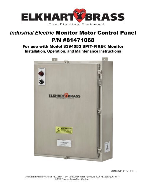
<strong>Industrial</strong> <strong>Electric</strong> <strong>Monitor</strong> <strong>Motor</strong> <strong>Control</strong> <strong>Panel</strong><br />
P/N #81471068<br />
For use with Model 8394053 SPIT-FIRE® <strong>Monitor</strong><br />
Installation, Operation, and Maintenance Instructions<br />
1302 WEST BEARDSLEY AVENUE P.O. BOX 1127 ELKHART IN 46515 (574) 295-8330 FAX (574) 293-9914<br />
© 2012 ELKHART BRASS MFG. CO., INC.<br />
98386000 REV. REL
PRODUCT SAFETY<br />
Important: Before installing and operating this equipment, read & study this manual<br />
thoroughly. Proper installation is essential to safe operation. In addition, the following points<br />
should be adhered to in order to ensure the safety of equipment and personnel:<br />
All personnel who may be expected to operate this equipment must be thoroughly trained in its safe and<br />
proper use.<br />
Before flowing water from this device, check that all personnel (fire service and civilian) are clear of the<br />
stream path. Also confirm stream direction will not cause avoidable property damage.<br />
Become thoroughly familiar with the hydraulic characteristics of this equipment, and the pumping<br />
system used to supply it. To produce effective fire streams, operating personnel must be properly<br />
trained.<br />
Whenever possible, this equipment should be operated from a remote location to avoid exposing<br />
personnel to dangerous fire conditions.<br />
Always open and close valves supplying this equipment slowly, so that the piping fills with water<br />
slowly, thus preventing the possible occurrence of water hammer.<br />
After each use, and on a scheduled basis, inspect equipment per instructions in the maintenance section.<br />
Disconnect power prior to servicing controls.<br />
Any modifications to the electrical enclosure will destroy the NEMA 4 rating and void warranty<br />
coverage of the enclosure and all components within.<br />
All equipment must be installed in accordance with local codes (NFPA 70 or EN/IEC 60079-14) as<br />
appropriate and in areas where equipment classification is suitable.<br />
WARNING: Do not attempt to disconnect or work on any electrical equipment in this<br />
system unless power is removed or the area is known to be non-hazardous.<br />
SYSTEM INFORMATION:<br />
SERIAL NUMBER: ______________________________<br />
DETAILS:<br />
__________________________________________________________________________________________<br />
__________________________________________________________________________________________<br />
__________________________________________________________________________________________<br />
2
TABLE OF CONTENTS<br />
I OVERVIEW 4<br />
II INSTALLATION INSTRUCTIONS 5<br />
III<br />
A. Component Mounting<br />
B. Interconnecting and Wiring <strong>Control</strong> System<br />
C. MMCP Fuse and Wiring<br />
SPECIFICATIONS 8<br />
IV OPERATING INSTRUCTIONS 8<br />
V MAINTENANCE 8<br />
VI TROUBLESHOOTING 9<br />
VII MOUNTING DIMENSIONS 10<br />
*For the most up-to-date documentation and specifications, please visit our website at www.elkhartbrass.com<br />
3
I OVERVIEW<br />
The primary function of the <strong>Monitor</strong> <strong>Motor</strong> <strong>Control</strong> <strong>Panel</strong> (MMCP) is to control the monitor and nozzle in a<br />
controlled environment or from a remote location. This is accomplished by receiving an electric signal from a<br />
Master/Local/Network <strong>Control</strong> <strong>Panel</strong> (Operator <strong>Control</strong> <strong>Panel</strong> – OCP), and then engaging the associated relay<br />
for the connected monitor which then executes the required function. This panel has a default wiring<br />
configuration of 220 VAC 60 Hz. The panel can be reconfigured to accommodate different input voltage.<br />
See section II.C for details. If the input voltage configuration is changed there are labels that need to be<br />
placed over the voltage configuration (P/N 44724000). The change can be accomplished in the field or<br />
ordered from <strong>Elkhart</strong> <strong>Brass</strong> with the correct input voltage. The following are the new part numbers that are<br />
associated with the conversions:<br />
81471070 – MMCP 81471068 Wired for 110/120 VAC 50/60 Hz.<br />
81471071 – MMCP 81471068 Wired for 220/240 VAC 50 Hz.<br />
81471072 – MMCP 81471068 Wired for 440/480 VAC 50/60 Hz.<br />
<strong>Electric</strong> <strong>Monitor</strong> <strong>Control</strong> <strong>Panel</strong> Features:<br />
Construction – Stainless Steel enclosure rated for Hazardous Location (Class 1, Division 2)<br />
Compliance – (NFPA 70) NEC: 2008, Article 501 – Class I, Groups “B,C, & D,” Division 2 & Article<br />
505 – Class I, Zone 2, AEx nA IIC T3 requirements; UL Labeled<br />
<strong>Control</strong> Power – On/Off 2-Position selector switch<br />
Pilot Light – Shows panel power on<br />
Internal Power – 24 VDC Power Supply for controls<br />
<strong>Control</strong> Relays – 24 VDC, 37mA relay inputs for: <strong>Monitor</strong> directions (UP, DOWN, LEFT, and<br />
RIGHT), Nozzle (STRAIGHT STREAM and FOG).<br />
Water Valve and Auxiliary Device Options – Fused external 24VDC or 120VAC power for operation<br />
of valve or device per system requirements.<br />
Water Valve position Feedback and Auxiliary Device Feedback Options – Terminal block relays are<br />
supplied for 24VDC or 120VAC voltage systems to provide feedback of the device being operated.<br />
Conduit Knockouts and Hubs – Supplied by others.<br />
WARNING: Do not disassemble or take cover off any <strong>Monitor</strong> <strong>Motor</strong>s. If cover is/has<br />
been removed, the warranty is void and the service life of the motor is significantly reduced.<br />
4
II INSTALLATION INSTRUCTIONS<br />
A. Component Mounting<br />
<strong>Monitor</strong> <strong>Motor</strong> <strong>Control</strong> <strong>Panel</strong> (MMCP) Installation<br />
1. This recommended distance the enclosure should be located from the <strong>Monitor</strong> Junction Box is 100<br />
feet (30.48m). For other distances and wire sizes refer to chart in Figure 4.<br />
2. Install the <strong>Panel</strong> approximately 3-4 feet (.91 to 1.22m) above grade and in the vertical position, on<br />
a rigid structure. Installation is normally at the base of the riser.<br />
3. The enclosure has four (4) mounting pads with .44” (11.18mm) diameter holes. Mounting hole<br />
centers are 18” (457.20mm) horizontal by 31.25” (793.75mm) vertical. Please refer to Figure 6 on<br />
page 10 for dimensional drawing.<br />
4. Use hubs and glands appropriate for the area classification they will be used in. Also, adhere to<br />
local code requirements for all electrical connections.<br />
B. Interconnecting and Wiring <strong>Control</strong> System – Wiring Connection Details Are Inside <strong>Panel</strong> Door<br />
Main Power to MMCP<br />
1. Install conduit from the main power distribution breaker box to <strong>Monitor</strong> <strong>Motor</strong> <strong>Control</strong> <strong>Panel</strong>.<br />
MMCPs are not provided with conduit hubs unless special ordered.<br />
2. Wiring for any voltage requires a minimum of three conductors. If using 480 VAC only one phase<br />
is required or two legs. The third leg need not be run but can be terminated on the blank spare<br />
terminal. Always remember to run a ground with all cable runs. Wire to be sized to accommodate<br />
a minimum of 500 VA.<br />
3. For wiring information and sizing see MMCP Fuse and Wiring Section - Figure 1.<br />
NOTE: Attachable labels, showing the separate wiring configurations, have been provided<br />
with the panel to document the configured panel and part number per the end users<br />
requirements. Once changed cut out the correct label and peel off the backing and place over<br />
the old configuration.<br />
MMCP to <strong>Monitor</strong> Junction Box<br />
1. Install conduit between MMCP and Junction Box, located at flanged base of monitor. Junction<br />
boxes are provided with 1 ½” NPT Conduit Hubs.<br />
2. To connect these boxes ten (10) conductors are required with conductor size to be determined by<br />
distance run. (For wiring information and sizing see MMCP Fuse and Wiring - Figure 4)<br />
Master/Network/Local Operator <strong>Control</strong> <strong>Panel</strong> to MMCP<br />
1. Install conduit between MMCP and Master/Local/Network <strong>Control</strong> Box.<br />
2. A minimum of fourteen (14) conductors plus spares are required PER MONITOR. (For wiring<br />
information and sizing see MMCP Fuse and Wiring Section - Figure 3)<br />
MMCP to optional Water Valve or Auxiliary Device<br />
1. Install conduit between MMCP and valve.<br />
2. The number of conductors will be determined by the device that is going to be controlled.<br />
Provisions have been designed in to the panel to accommodate various scenarios. As this is a<br />
generic manual the number of conductor cannot be accurately given this will be determined by the<br />
end user. (For wiring information and sizing see MMCP Fuse and Wiring Section – Figure 3 and<br />
Figure 5)<br />
5
Isolated Normally Open Dry Contacts<br />
1. Each MMCP has been supplied with a set of normally open dry contacts that can be used per<br />
customer requirements. They are rated for 600VAC, 5 Amps and are closed when the water valve<br />
or auxiliary device relays are energized.<br />
WARNING: Make sure panels are grounded according to area classification and<br />
company policy to assure panel code compliance.<br />
C. MMCP Fuse and Wiring<br />
Figure 1: MMCP Fuse and Jumper Diagram<br />
Figure 2: Typical MMCP Fuse and Jumper Diagram<br />
6
WIRE SIZE FOR CONDUCTORS BETWEEN MONITOR<br />
MOTOR CONTROL PANEL AND<br />
OPERATOR CONTROL PANEL OR VALVES<br />
CONDUCTOR LENGTH WIRE SIZE<br />
UP TO 750 FEET (228 m) 18 AWG (0.75 mm 2 )<br />
750 TO 1500 FEET (457 m) 16 AWG (1.0 mm 2 )<br />
1500 TO 2500 FEET (762 m) 14 AWG (2.5 mm 2 )<br />
2500 TO 3500 FEET (1066 m) 12 AWG (4.0 mm 2 )<br />
Figure 3: MMCP - OCP Wiring Chart Figure 4: MMCP – <strong>Monitor</strong> Junction Box<br />
Wiring Chart<br />
Figure 5: #81471068 MMCP/<strong>Monitor</strong> <strong>Motor</strong>s - (Optional Valve and Auxiliary Device) Wiring Diagram<br />
7<br />
WIRE SIZE FOR CONDUCTORS BETWEEN<br />
MONITOR MOTOR CONTROL PANEL AND MONITOR<br />
JUNCTION BOX<br />
CONDUCTOR LENGTH WIRE SIZE<br />
UP TO 75 FEET (22 m) 18 AWG (0.75 mm 2 )<br />
75 TO 100 FEET (30 m) 16 AWG (1.0 mm 2 )<br />
100 TO 200 FEET (60 m) 14 AWG (2.5 mm 2 )<br />
200 TO 400 FEET (121 m) 12 AWG (4.0 mm 2 )
III SPECIFICATIONS<br />
General Specs<br />
Input Power 120/240 VAC (50/60Hz.)<br />
440/480 VAC (50/60 Hz.)<br />
500 VA max. Power<br />
<strong>Electric</strong>al Load 5 AMPS MAX at 120/240 VAC<br />
1 AMP MAX at 440/480 VAC<br />
Fused Output Power 24 VDC – 5 AMPS MAX<br />
120 VAC – 3 AMPS MAX<br />
<strong>Panel</strong> Dimensions 24” X 30” (610 mm x 762 mm)<br />
<strong>Panel</strong> Weight Approx. 100 lbs (45 kg)<br />
Operating Temperature Range +14 o F to +158 o F (-10 o C to +70 o C)<br />
UL and ATEX Product Marking (if ordered)<br />
UL Inspected and Labeled (Class 1, Division 2)<br />
CE ATEX certification available upon advanced request<br />
IV OPERATING INSTRUCTIONS<br />
This control panel has one ON/OFF 2-position selector switch. Move it to the ON position so the pilot light<br />
illuminates, showing the panel is now powered up, and ready for associated monitor operation.<br />
V MAINTENANCE<br />
Monthly Inspection and Maintenance<br />
1. Check the indicator light and replace bulb if it’s not operable.<br />
2. Confirm that all terminal blocks and connections are properly taut to 4.5 – 7.1 in-lbs. (0.508 – 0.802<br />
Nm).<br />
3. Check for proper operation of the system overall, if there are problems with the system please refer to<br />
the Troubleshooting section for help.<br />
8
VI TROUBLESHOOTING<br />
A. If <strong>Panel</strong> will not power up:<br />
1. Check the incoming supply power, and if it’s the proper power requirement for the system.<br />
2. Check to make sure the transformer is wired correctly.<br />
3. Check fuses in panel to confirm they are good. If fuses are blown, replace them with same or<br />
equivalent fuse.<br />
a. Check for causes in the interconnect wiring and connections.<br />
b. Verify that the OCP is not trying to activate the monitor motor functions<br />
c. If nothing is found consult with your <strong>Elkhart</strong> <strong>Brass</strong> representative.<br />
4. Check panel power switch to make sure it is in the “Power On” position.<br />
5. Check power supply to confirm there is 120 VAC running to it.<br />
B. If Pilot Light is not on when panel has power:<br />
1. Check the light bulb, and replace if it is burnt out.<br />
C. Function not working correctly:<br />
1. Check to see if there is a loose connection at the terminal blocks or contact blocks. Make sure all<br />
screw terminations are properly tightened to 4.5 – 7.1 in-lbs (0.508 – 0.802 Nm)<br />
2. Check relay for actuation. If bad, replace relay with new working relay.<br />
Any problems that cannot be fixed/solved with this troubleshooting guide should be taken to your<br />
<strong>Elkhart</strong> <strong>Brass</strong> Representative to get further information.<br />
WARNING: Do not attempt to disconnect or work on any electrical equipment in this<br />
system unless power is removed or the area is known to be non-hazardous.<br />
9
VII MOUNTING DIMENSIONS<br />
Figure 6: MMCP Mounting Dimensions<br />
10
NOTES:__________________________________________________________________________________<br />
__________________________________________________________________________________________<br />
__________________________________________________________________________________________<br />
__________________________________________________________________________________________<br />
__________________________________________________________________________________________<br />
__________________________________________________________________________________________<br />
__________________________________________________________________________________________<br />
__________________________________________________________________________________________<br />
__________________________________________________________________________________________<br />
__________________________________________________________________________________________<br />
__________________________________________________________________________________________<br />
__________________________________________________________________________________________<br />
__________________________________________________________________________________________<br />
__________________________________________________________________________________________<br />
__________________________________________________________________________________________<br />
__________________________________________________________________________________________<br />
__________________________________________________________________________________________<br />
__________________________________________________________________________________________<br />
__________________________________________________________________________________________<br />
__________________________________________________________________________________________<br />
__________________________________________________________________________________________<br />
__________________________________________________________________________________________<br />
__________________________________________________________________________________________<br />
__________________________________________________________________________________________<br />
__________________________________________________________________________________________<br />
__________________________________________________________________________________________<br />
__________________________________________________________________________________________<br />
__________________________________________________________________________________________<br />
__________________________________________________________________________________________<br />
__________________________________________________________________________________________<br />
__________________________________________________________________________________________<br />
__________________________________________________________________________________________<br />
__________________________________________________________________________________________<br />
________________________________________________________________________________<br />
11


