troubleshooting the 8494 electric sidewinder - Elkhart Brass
troubleshooting the 8494 electric sidewinder - Elkhart Brass
troubleshooting the 8494 electric sidewinder - Elkhart Brass

Create successful ePaper yourself
Turn your PDF publications into a flip-book with our unique Google optimized e-Paper software.
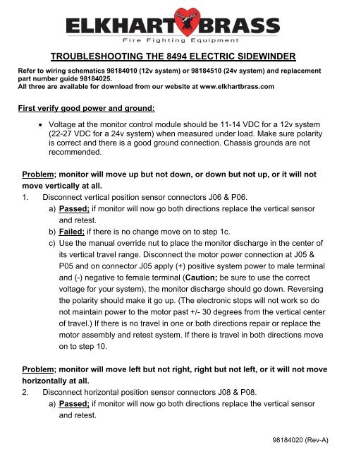
TROUBLESHOOTING THE <strong>8494</strong> ELECTRIC SIDEWINDER<br />
Refer to wiring schematics 98184010 (12v system) or 98184510 (24v system) and replacement<br />
part number guide 98184025.<br />
All three are available for download from our website at www.elkhartbrass.com<br />
First verify good power and ground:<br />
<br />
Voltage at <strong>the</strong> monitor control module should be 11-14 VDC for a 12v system<br />
(22-27 VDC for a 24v system) when measured under load. Make sure polarity<br />
is correct and <strong>the</strong>re is a good ground connection. Chassis grounds are not<br />
recommended.<br />
Problem; monitor will move up but not down, or down but not up, or it will not<br />
move vertically at all.<br />
1. Disconnect vertical position sensor connectors J06 & P06.<br />
a) Passed; if monitor will now go both directions replace <strong>the</strong> vertical sensor<br />
and retest.<br />
b) Failed; if <strong>the</strong>re is no change move on to step 1c.<br />
c) Use <strong>the</strong> manual override nut to place <strong>the</strong> monitor discharge in <strong>the</strong> center of<br />
its vertical travel range. Disconnect <strong>the</strong> motor power connection at J05 &<br />
P05 and on connector J05 apply (+) positive system power to male terminal<br />
and (-) negative to female terminal (Caution; be sure to use <strong>the</strong> correct<br />
voltage for your system), <strong>the</strong> monitor discharge should go down. Reversing<br />
<strong>the</strong> polarity should make it go up. (The electronic stops will not work so do<br />
not maintain power to <strong>the</strong> motor past +/- 30 degrees from <strong>the</strong> vertical center<br />
of travel.) If <strong>the</strong>re is no travel in one or both directions repair or replace <strong>the</strong><br />
motor assembly and retest system. If <strong>the</strong>re is travel in both directions move<br />
on to step 10.<br />
Problem; monitor will move left but not right, right but not left, or it will not move<br />
horizontally at all.<br />
2. Disconnect horizontal position sensor connectors J08 & P08.<br />
a) Passed; if monitor will now go both directions replace <strong>the</strong> vertical sensor<br />
and retest.<br />
98184020 (Rev-A)
) Failed; no change move on to step 2c.<br />
c) A; Use <strong>the</strong> manual override nut to place <strong>the</strong> monitor in <strong>the</strong> center of its<br />
horizontal travel range. Disconnect <strong>the</strong> motor power connection at J07 &<br />
P07 and on connectorJ07 apply (+) positive system power to <strong>the</strong> male<br />
terminal and (-) negative to female terminal (Caution; be sure to use <strong>the</strong><br />
correct voltage for your system), <strong>the</strong> monitor should go left. Reversing <strong>the</strong><br />
polarity should make it go right. (The electronic stops will not work so do not<br />
maintain power to <strong>the</strong> motor past +/- 45 degrees from <strong>the</strong> horizontal center<br />
of travel.) If <strong>the</strong>re is no travel in one or both directions repair or replace <strong>the</strong><br />
motor assembly and retest system. If <strong>the</strong>re is travel in both directions move<br />
on to step 10.<br />
Problem; nozzle will go into fog but not stream or stream but not fog or will not<br />
move at all.<br />
3. Disconnect fog/stream motor power connectors J09 & P09 and on connector J09<br />
apply (+) positive system voltage to male terminal and (-) negative to female<br />
terminal (Caution; be sure to use <strong>the</strong> correct voltage for your system). The nozzle<br />
tip should pull back for fog. Reverse polarity to push <strong>the</strong> nozzle tip forward for<br />
straight stream. The override nut on <strong>the</strong> nozzle actuator should free spin at both<br />
ends of travel.<br />
a) Passed; if nozzle actuator will move <strong>the</strong> tip in both directions smoothly<br />
move on to step 10.<br />
b) Failed; if nozzle actuator will not move <strong>the</strong> tip in both directions or <strong>the</strong><br />
movement is not smooth and <strong>the</strong> nozzle binds preventing full travel in ei<strong>the</strong>r<br />
direction, repair or replace <strong>the</strong> nozzle and retest <strong>the</strong> system.<br />
Problem; monitor or nozzle moves without operating any switches on <strong>the</strong><br />
Joystick or Switch box control.<br />
4. Disconnect <strong>the</strong> Joystick or Switch box control connector at J01 & P01.<br />
a) If movement ceases repair or replace controller, if not move to step 4b.<br />
b) Disconnect control harness at J02 & P02. If movement ceases replace <strong>the</strong><br />
control harness, if not replace <strong>the</strong> monitor control module.
Problem; monitor will not stop at intended horizontal travel limits.<br />
5. Disconnect horizontal position sensor connectors J08 & P08. In connector P08<br />
check for hall sensor power (+7.5 to 12 VDC) at terminal 3 (red wire), left/right<br />
sensor signal voltage (+4.5 to 7.5 VDC) at terminal 2 (white wire), and ground at<br />
terminal 1 (black wire).<br />
a) Passed; if all values were within specifications. Move on to step 9b.<br />
b) Failed; one or more values did not meet specifications. Move on to step 6.<br />
6. Move to <strong>the</strong> next connector in <strong>the</strong> harness towards <strong>the</strong> monitor control module<br />
and check for hall sensor power (+7.5 to 12 VDC) at terminal position C, left/right<br />
sensor signal voltage (+4.5 to 7.5 VDC) at terminal position H, and ground at<br />
terminal position K. (There may be an extension harness or harnesses between<br />
connectors P4 and J4.)<br />
a) Passed; if all values were within specifications replace monitor harness and<br />
retest system.<br />
b) Failed; if all values were not within specifications;<br />
1. If this connector was on <strong>the</strong> output pigtail from <strong>the</strong> monitor<br />
control module <strong>the</strong>n replace <strong>the</strong> monitor control module, reconnect<br />
harnesses, and go back and repeat step 5.<br />
2. If this connector was on an extension harness move to next<br />
connector in <strong>the</strong> harness towards <strong>the</strong> monitor control module and<br />
check for hall sensor power (+7.5 to 12 VDC) at terminal position C,<br />
left/right sensor signal voltage (+4.5 to 7.5 VDC) at terminal position<br />
H, and ground at terminal position K. If all values were not within<br />
specifications move to next connector in <strong>the</strong> harness towards <strong>the</strong><br />
monitor control module and continue testing until you get <strong>the</strong> correct<br />
values in which case you replace <strong>the</strong> previous harness extension or<br />
until you reach <strong>the</strong> control module and still do not get <strong>the</strong> correct<br />
values in which case you replace <strong>the</strong> control module. In ei<strong>the</strong>r case<br />
reconnect harnesses, and go back and repeat step 5.
Problem; monitor will not stop at intended vertical travel limits.<br />
7. Disconnect vertical position sensor connectors J06 & P06. In connector P06<br />
check for hall sensor power (+7.5 to 12 VDC) at terminal 3 (red wire), left/right<br />
sensor signal voltage (+4.5 to 7.5 VDC) at terminal 2 (white wire), and ground at<br />
terminal 1 (black wire).<br />
a) Passed; if all values were within specifications. Move on to step 9a.<br />
b) Failed; one or more values did not meet specifications. Move on to step 8.<br />
8. Move to <strong>the</strong> next connector in <strong>the</strong> harness towards <strong>the</strong> monitor control module<br />
and check for hall sensor power (+7.5 to 12 VDC) at terminal position C, up/down<br />
sensor signal voltage (+4.5 to 7.5 VDC) at terminal position J, and ground at<br />
terminal position K. (There may be an extension harness or harnesses between<br />
connectors P4 and J4.)<br />
If this connector was on an extension harness move to next connector in <strong>the</strong><br />
harness towards <strong>the</strong> monitor control module and check for hall sensor power<br />
(+7.5 to 12 VDC) at terminal position C, left/right sensor signal voltage (+4.5 to<br />
7.5 VDC) at terminal position J, and ground at terminal position K. If all values<br />
were not within specifications move to next connector in <strong>the</strong> harness towards <strong>the</strong><br />
monitor control module and continue testing until you get <strong>the</strong> correct values (in<br />
which case you replace <strong>the</strong> previous harness extension) or until you reach <strong>the</strong><br />
control module and still do not get <strong>the</strong> correct values (in which case you replace<br />
<strong>the</strong> control module). In ei<strong>the</strong>r case reconnect harnesses, and go back and repeat<br />
step 7.<br />
9. Checking <strong>the</strong> monitor control modules travel limit function using a jumper.<br />
a) Testing <strong>the</strong> vertical limits; While moving <strong>the</strong> monitor up <strong>electric</strong>ally place <strong>the</strong><br />
jumper between terminal positions 1 & 2 in connector P06. The monitor<br />
should stop and only allow downward travel until <strong>the</strong> jumper is removed.<br />
Remove <strong>the</strong> jumper and repeat <strong>the</strong> test while going down and <strong>the</strong> monitor<br />
should stop and only allow upward travel until <strong>the</strong> jumper is removed.<br />
b) Testing <strong>the</strong> horizontal limits; While moving <strong>the</strong> monitor left <strong>electric</strong>ally place<br />
<strong>the</strong> jumper between terminal positions 1 & 2 in connector P08. The monitor<br />
should stop and only allow travel to <strong>the</strong> right until <strong>the</strong> jumper is removed.<br />
Remove <strong>the</strong> jumper and repeat <strong>the</strong> test while going right and <strong>the</strong> monitor<br />
should stop and only allow travel to <strong>the</strong> left until <strong>the</strong> jumper is removed.
Passed; if all testing was within specifications replace <strong>the</strong> corresponding travel<br />
limit sensor and retest system.<br />
Failed; if all tests were not within specifications move to <strong>the</strong> connector J04 on<br />
<strong>the</strong> output pigtail from <strong>the</strong> monitor control module and retest using a meter<br />
attached to <strong>the</strong> up/down or left/right motor power terminals. See if placing a<br />
jumper between terminals H and K for left/right or J and K for up/down while<br />
corresponding motor output power is present will terminate power for that<br />
direction and only allow power in <strong>the</strong> opposite direction. If motor power is not<br />
terminated as described replace <strong>the</strong> monitor control module. Reconnect<br />
harnesses and sensor and retest to see if travel limits are now working.<br />
10. Find <strong>the</strong> wire for <strong>the</strong> function that is not working (left, right, up, down, fog, or<br />
stream) in connector P02. Placing a jumper between that terminal and <strong>the</strong> ground<br />
terminal in position C should result in <strong>the</strong> desired output on <strong>the</strong> terminals for motor<br />
power in connector J04. (Example; monitor won’t go left, a jumper between<br />
terminals in positions G (left) and C (ground) in connector P02 should result in<br />
Positive (+) motor power on terminal D and Negative (-) power on terminal C in<br />
connector J04.)<br />
a) Passed; if <strong>the</strong> correct motor power outputs are present on <strong>the</strong> correct<br />
terminals in connector J04 remove jumper and go on to step 11.<br />
b) Failed; if <strong>the</strong> correct motor power outputs are not present replace <strong>the</strong><br />
monitor control module and, reconnect all harnesses, & retest system.<br />
11. Reconnect <strong>the</strong> harnesses one at a time on <strong>the</strong> monitor side of <strong>the</strong> control module<br />
and check for correct motor power at <strong>the</strong> end terminals when using a jumper<br />
between <strong>the</strong> same terminals as in step 11. If correct motor power is not present<br />
replace <strong>the</strong> harness and repeat <strong>the</strong> test. Keep going until correct power is present at<br />
<strong>the</strong> appropriate motor power connector (P05, P07, or P09). Leave <strong>the</strong> meter<br />
connected to <strong>the</strong> motor power leads and go on to step 12.
12. Move to <strong>the</strong> control side of <strong>the</strong> monitor control module and plug in connectors<br />
J02 & P02. Go to connector P01 and inspect <strong>the</strong> connector to be sure <strong>the</strong> terminal<br />
sockets for <strong>the</strong> ground and function you are testing are in place correctly. Use a<br />
jumper between <strong>the</strong> terminal sockets for <strong>the</strong> same function you have been testing<br />
a) Passed; if <strong>the</strong> correct motor power outputs are present on <strong>the</strong> appropriate<br />
motor power connector go on to step 13.<br />
b) Failed; if <strong>the</strong> correct motor power outputs are not present replace <strong>the</strong><br />
monitor control harness and repeat step 12.<br />
13. Inspect <strong>the</strong> contact pins in <strong>the</strong> J01 connector on <strong>the</strong> joystick or switch box that<br />
correspond to <strong>the</strong> common ground and function that you are testing for damage.<br />
a) Passed: no visible damage to <strong>the</strong> contact pins. Go to step 14.<br />
b) Failed: damaged pin or pins found. Repair or replace <strong>the</strong> joystick or switch<br />
box controller, reconnect all harnesses and retest system.<br />
14. Test <strong>the</strong> joystick or switch box by checking for continuity between <strong>the</strong> common<br />
ground contact pin and <strong>the</strong> function contact pin while <strong>the</strong> switch is being activated<br />
for that function. Power to <strong>the</strong> joystick or switch box is not required.<br />
a) Passed: continuity was found between <strong>the</strong> common ground contact pin and<br />
<strong>the</strong> function contact pin while <strong>the</strong> switch was activated for that function.<br />
Move on to step 15.<br />
b) Failed: continuity was not found between <strong>the</strong> common ground contact pin<br />
and <strong>the</strong> function contact pin for <strong>the</strong> function being tested while <strong>the</strong> switch is<br />
being activated for that function. Repair or replace <strong>the</strong> joystick or switch box<br />
controller, reconnect all harnesses and test system.
15. If everything has passed <strong>the</strong> testing in steps 12, 13, & 14 look for a problem with<br />
<strong>the</strong> P01 connector fitting loosely in <strong>the</strong> mating connector J01 on <strong>the</strong> controller or a<br />
loose or broken wire in <strong>the</strong> P01 connection. Make sure <strong>the</strong> connectors are<br />
connected properly and that <strong>the</strong> lock ring on connector P01 is secured onto<br />
connector J01. Gently move <strong>the</strong> P01 connector around up and down and side to<br />
side while activating <strong>the</strong> function switch.<br />
a) Passed: function was not interrupted by movement of <strong>the</strong> connector. Go to<br />
step 16.<br />
b) Failed: function control is interrupted or comes and goes. Replace <strong>the</strong><br />
control harness, reconnect system harnesses and test system.<br />
16. Gently move <strong>the</strong> wires going into <strong>the</strong> P01 connector around up and down and<br />
side to side while activating <strong>the</strong> function switch. If function control is interrupted or<br />
comes and goes. Replace <strong>the</strong> control harness, reconnect system harnesses and<br />
test system.<br />
Summary;<br />
We have tried to cover <strong>the</strong> most likely problems that can occur with <strong>the</strong> <strong>8494</strong> <strong>electric</strong><br />
Sidewinder system. The monitor control module is <strong>the</strong> heart of <strong>the</strong> system. Power and<br />
ground are fed into <strong>the</strong> module. Wires for each function come from <strong>the</strong> control side of<br />
<strong>the</strong> module and carry signal voltage. Switching one of <strong>the</strong>se function wires to <strong>the</strong><br />
common ground from control side of <strong>the</strong> module results in motor power being sent out<br />
from <strong>the</strong> monitor side of <strong>the</strong> module to <strong>the</strong> appropriate motor in <strong>the</strong> polarity needed for<br />
<strong>the</strong> chosen function. This <strong>troubleshooting</strong> guide is going to help diagnose whe<strong>the</strong>r <strong>the</strong><br />
problem is on <strong>the</strong> monitor side of <strong>the</strong> control module, <strong>the</strong> controller side of <strong>the</strong> module,<br />
or with <strong>the</strong> module itself.<br />
If you have any questions contact Technical Service at (800) 346-0250.