Masoneilan Models 496-1 and 496-2 Rotary Electric Switches ...
Masoneilan Models 496-1 and 496-2 Rotary Electric Switches ...
Masoneilan Models 496-1 and 496-2 Rotary Electric Switches ...

You also want an ePaper? Increase the reach of your titles
YUMPU automatically turns print PDFs into web optimized ePapers that Google loves.
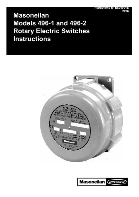
<strong>Masoneilan</strong><br />
<strong>Models</strong> <strong>496</strong>-1 <strong>and</strong> <strong>496</strong>-2<br />
<strong>Rotary</strong> <strong>Electric</strong> <strong>Switches</strong><br />
Instructions<br />
Instructions N° ES70004E<br />
09/96
description <strong>and</strong> operation<br />
Description (Figure 2)<br />
Series <strong>496</strong> rotary switches are used for electrically<br />
indicating one or two predetermined positions in the<br />
stroke of a control valve. They may be connected to<br />
audible alarms or signal lights for warning of valve or<br />
system malfunction. These switches may also be used<br />
to actuate solenoids, relays <strong>and</strong> other electrical devices.<br />
Basic switches (4) in the unit are single pole, double<br />
throw snap acting <strong>and</strong> are individually adjusted by cams<br />
(13) on the rotating shaft (11). Vernier adjustment is<br />
made by means of locking type set screws (Nylock) (2)<br />
in the cams <strong>and</strong> these screws actuate the switches by<br />
contacting the switch spring levers (5).<br />
The spring levers provide overtravel protection <strong>and</strong> allow<br />
maintained contact when required.<br />
The series <strong>496</strong> is available with either one or two<br />
switches, each with an adjustable cam to actuate it.<br />
The housing <strong>and</strong> cover are of anodized aluminum,<br />
epoxy painted.<br />
<strong>496</strong><br />
Instrument Type<br />
1. Mechanical switch with one single pole,<br />
double throw contact arrangement<br />
2. Mechanical switch with two single poles,<br />
double throw contact arrangement<br />
3. Potentiometric Position Transmitter<br />
4. Electronic switch with one proximity<br />
detector<br />
5. Electronic switch with two proximity<br />
detectors<br />
6. Mechanical switch with one double pole,<br />
double throw contact arrangement<br />
7. Mechanical switch with two double poles,<br />
double throw contact arrangement<br />
8. Optoelectronic Position Transmitter<br />
1 st 2 nd<br />
2<br />
Series <strong>496</strong> switches may be mounted on the CamflexII<br />
rotary valves (35002 Series) or Varimax (30000 Series),<br />
Control BallII valves (36002 Series), butterfly valves as<br />
M i n i To r k II (37002 Series) or HPBV (39002 Series)<br />
valves.<br />
Also, they may be used on valves as the 11 000, 21000<br />
<strong>and</strong> 41000 Series <strong>and</strong> all other linear motion valves. A<br />
parts list for the Series <strong>496</strong> switch appears in page 4.<br />
Operation (Figure 2)<br />
The motion of the control valve turns (by means of a<br />
linkage the switch shaft (11). Cams (13), fastened to the<br />
shaft by screws (1), actuate microswitches (4) by<br />
pushing levers (5).<br />
Each switch may be wired to either open or close the<br />
circuit when the lever is depressed.<br />
NUMBERING SYSTEM OF THE <strong>496</strong> SERIE<br />
Caution: <strong>Electric</strong>al protection of some of the above mentioned equipment<br />
combinations, can be not in accordance with all protection st<strong>and</strong>ards.<br />
Consult <strong>Masoneilan</strong>.<br />
Protection<br />
55. Weatherproof (E)<br />
56. Weatherproof, oxygen<br />
environment (E)<br />
57. Explosionproof <strong>and</strong><br />
weatherproof (E)<br />
58. Intrinsically safe <strong>and</strong><br />
weatherproof (E)<br />
These two digits are used<br />
only when European<br />
st<strong>and</strong>ards are concerned.<br />
Otherwise the instrument is<br />
explosionproof <strong>and</strong><br />
weatherproof (US)<br />
E= European st<strong>and</strong>ards<br />
3 rd<br />
Additional Switch* (if any)<br />
1. Mechanical switch with one single pole,<br />
double throw contact arrangement<br />
2. Mechanical switch with two single poles,<br />
double throw contact arrangement<br />
4. Electronic switch with one proximity<br />
detector<br />
5. Electronic switch with two proximity<br />
detectors<br />
6. Mechanical switch with one double pole,<br />
double throw contact arrangement<br />
7. Mechanical switch with two double poles,<br />
double throw contact arrangement<br />
* This digit <strong>and</strong> its oblique bar is only used when the<br />
transmitter is provided with an auxiliary switch
installation <strong>and</strong> adjustments<br />
Installation<br />
<strong>Electric</strong>al Protection<br />
The microswitches <strong>and</strong> other parts are protected by a<br />
flameproof housing<br />
EN 50014 & 50018<br />
EExdIICT6 (ambient temperature ≤70°C)<br />
EExdIICT5 (ambient temperature ≤80°C)<br />
Beside, a tight degree up to IP65 following to st<strong>and</strong>ard<br />
CEI 144 <strong>and</strong> IP657 following to st<strong>and</strong>ard NFC 20.010 is<br />
ensured by the O-rings (7& 10) located between body<br />
<strong>and</strong> cover <strong>and</strong> on the switch shaft.<br />
Installation of the rotary limit switches into i n t r i n s i c<br />
safety circuit according to following European<br />
st<strong>and</strong>ards (CENELEC):<br />
EN 50014 & 50020<br />
EExiaIICT6 (ambient temperature –55°C +80°C)<br />
N o t e : The load must be controlled through a<br />
certified transistorized relay located outside the<br />
hazardous area.<br />
<strong>Electric</strong>al Connection-Wiring (Figure 1)<br />
A cable entry is integrated at the bottom of the housing<br />
<strong>and</strong> includes a cable clamping device. Diff e r e n t<br />
leakproof packings allow the adaptation of diameters of<br />
unarmed cables from 6 to 15mm.<br />
Figure 1<br />
Wiring Diagram <strong>and</strong> Dimensions for Mounting<br />
3<br />
The cable entry is also available in 3/4”NPT threaded<br />
connection form. This can be designed to answer most<br />
of the customer requests.<br />
Each microswitch has three terminals (“common”,<br />
“normally open” <strong>and</strong> “normally closed”), (See Figure 3).<br />
<strong>Electric</strong>al rating of switches is stamped on serial plate.<br />
The installation in hazardous locations should be<br />
according to the regulations in force concerning<br />
flameproof material.<br />
Coupling<br />
The coupling of the switch shaft to the valve is made by<br />
means of a back lever <strong>and</strong> a motion linkage proper to<br />
each valve configuration. The back lever is fastened to<br />
the switch shaft (11) with a washer <strong>and</strong> a hex. head<br />
s c r e w. Figures 3 to 6 show installation details on the<br />
various valves.
Adjustments<br />
The Series <strong>496</strong> switch is normally mounted <strong>and</strong> adjusted<br />
on a control valve at the factory. To adjust the instrument<br />
in the field, proceed as follows:<br />
1. The concave part of the levers (5) should be<br />
exactly concentric with the cams (13) when the<br />
switch is actuated.<br />
This is an important step to assure that once the<br />
lever is depressed, it stays depressed when the<br />
screw (2) is completely free.<br />
If not, loosen screws (3 <strong>and</strong> 17) <strong>and</strong> slide the levers<br />
up or down slightly. Tighten screws.<br />
2. Unscrew slightly the cam locking screws (1) using a<br />
3/32” Allen wrench.<br />
3. Actuate the valve to the desired position (usually the<br />
full opened or full closed position).<br />
4. It is important to note that the cam operating the<br />
right-h<strong>and</strong> switch should make contact with<br />
lever (5) only at the end of a counterclockwise<br />
rotation. (Refer to detail of the Figure 2).<br />
Contact point<br />
for left switch<br />
Contact point<br />
for right switch<br />
1 Screw<br />
2 Screw<br />
3 Fastening Screw (only one switch)<br />
4 Microswitch<br />
5 Lever<br />
6 Body<br />
● 7 O-Ring<br />
● Recommended Spare Parts<br />
* Only on <strong>496</strong>-2 Model<br />
PARTS REFERENCE<br />
8 Snap Ring<br />
9 Screw<br />
● 10 O-Ring<br />
11 Shaft<br />
12 Cover<br />
13 Cam<br />
14 Serial Plate<br />
4<br />
This assures that when the valves is throttling, the<br />
screw (2) is completely free of the lever. The<br />
concave part of the lever is only to maintain contact<br />
during over-travel (if any). Similarly, the cam<br />
operating the left-h<strong>and</strong> switch should make<br />
contact with lever (5) only at the end of a<br />
clockwise rotation. (Refer to face view of the<br />
Figure 2).<br />
If there is only one switch (Model <strong>496</strong>-1) it may be<br />
necessary to reverse the position of the switch from<br />
left to right or vice versa depending on the rotation<br />
<strong>and</strong> stroke position.<br />
5. Turn the cam (13) on the shaft until the switch is<br />
activated. (If the click switch cannot be heard, use a<br />
voltmeter). Lock the cam (13) with screw (1).<br />
6. Make a fine adjustment with screw (2) using a 1/16”<br />
Allen wrench. The screw (2) must extend out from<br />
the cam far enough to assure sufficient depression<br />
of lever (5).<br />
Figure 2<br />
Cutaway Views of Types <strong>496</strong>-1/2 <strong>Switches</strong><br />
Ref. Part Name Ref. Part Name Ref. Part Name<br />
15 Drive Screw<br />
16 Insulator<br />
17 Fastening Screw (second switch<br />
on <strong>496</strong>-2)<br />
18 Washer<br />
*19 Spacer (Not shown)
Mounting arrangements<br />
On 35002 Series Camflex II Valves (Figure 3):<br />
1. Remove shaft cover, or if equipped with a positioner,<br />
remove positioner <strong>and</strong> mounting plate.<br />
2. Remove bottom cover (2).<br />
3. Install mounting bracket (3) using two flat head<br />
screws (7).<br />
4. Screw pin (12) to switch lever (10).<br />
5. Remove cap screw (11) from switch lever (10) <strong>and</strong><br />
slide switch lever onto shaft, behind the main lever<br />
of the valve. Position switch lever (10) in line with<br />
main lever. Replace <strong>and</strong> tighten cap screw (11).<br />
Figure 3<br />
35002 Serie<br />
Camflex II Valve<br />
1 <strong>496</strong> <strong>Rotary</strong> Switch<br />
2 Bottom Cover<br />
3 Mounting Bracket<br />
4 Cap Screw<br />
5 Lock Washer<br />
CamflexII Valve<br />
Opening by Air Failure<br />
The linkage parts are shown<br />
WHEN NO SUPPLY PRESSURE ON ACTUATOR<br />
CamflexII Valve<br />
Closing by Air Failure<br />
PARTS REFERENCE<br />
6 Cap Screw<br />
7 Flat Head Screw<br />
8 Hex. Nut<br />
9 Back Lever<br />
10 Switch Lever<br />
5<br />
6. Mount switch (1) on bracket (3) using the four cap<br />
screws (4) <strong>and</strong> the four hex. nuts (8).<br />
7. For 3” (80mm) valve <strong>and</strong> larger, slip slotted bottom<br />
cover (2) over the lever (10) <strong>and</strong> push in place.<br />
8. Place slotted end of the back lever (9) over pin (12)<br />
of the switch lever (10). Secure with washer (13)<br />
<strong>and</strong> clip (14).<br />
9. Attach the back lever (9) to the switch shaft using<br />
lock washer (5) <strong>and</strong> cap screw (6).<br />
10. Refer to pages 3 & 4 to proceed with wiring <strong>and</strong><br />
adjusting switches.<br />
Val ve<br />
Val ve<br />
On valve size ≥ 3”<br />
Ref. Part Name Ref. Part Name Ref. Part Name<br />
11 Cap Screw (Switch Lever)<br />
12 Lever Pin<br />
13 Washer<br />
14 Retaining Clip
On 30000 Series Varimax Valves (Figure 4):<br />
1. Remove shaft cover, or if equipped with a positioner,<br />
remove positioner <strong>and</strong> mounting plate.<br />
2. Screw the index-screw (17), with its lock washer<br />
(18), into one of the two threaded holes of the switch<br />
lever (10).<br />
N o t e : The head of the index-screw (17) will be<br />
engaged in the slot located on the valve shaft end<br />
to ensure the proper position of the switch lever<br />
(10). The proper hole to the used configuration can<br />
be easily identified referring to the below Figure 4<br />
<strong>and</strong> presenting the lever in the shown position.<br />
3. By means of the hex. head screw (19), fit the switch<br />
lever (10) on the valve shaft end in the proper<br />
position relating to the valve operating way.<br />
Figure 4<br />
30000 Series<br />
Varimax Valves<br />
1 <strong>496</strong> <strong>Rotary</strong> Switch<br />
3 Mounting Bracket<br />
4 Cap Screw<br />
5 Lock Washer<br />
6 Hex. Head Screw<br />
7 Flat Head Screw<br />
Varimax Valve<br />
Opening<br />
by Air Failure<br />
The linkage parts are shown<br />
WHEN NO SUPPLY PRESSURE ON ACTUATOR<br />
Varimax Valve<br />
Closing<br />
by Air Failure<br />
PARTS REFERENCE<br />
8 Hex. Nut<br />
9 Back Lever<br />
10 Switch Lever<br />
12 Lever Pin<br />
13 Washer<br />
14 Retaining Clip<br />
6<br />
4. Install the mounting bracket (3) by means of the<br />
spacer (15) <strong>and</strong> the two flat head screws (7).<br />
5. Mount switch (1) on bracket (3) using the four cap<br />
screws (4) <strong>and</strong> the four hex. nuts (8).<br />
6. Attach the back lever (9) to the switch shaft using<br />
lock washer (5) <strong>and</strong> hex. head screw (6).<br />
7. Connect the back lever (9) to the switch lever (10)<br />
by means of link (20), two driving pins (12), four<br />
washers (13) <strong>and</strong> two retaining clips (14).<br />
8. Refer to pages 3 & 4 to proceed with wiring <strong>and</strong><br />
adjusting switches.<br />
Ref. Part Name Ref. Part Name Ref. Part Name<br />
15 Spacer (Mounting Bracket)<br />
17 Index-screw (Switch Lever)<br />
18 Lock Washer<br />
19 Hex. Head Screw<br />
20 Link
On 36002 Series Ball II, 37002 Series MiniTork II <strong>and</strong><br />
39002 Series HPBV Valves (Figure 5):<br />
1. Remove shaft cover, or if equipped with a positioner,<br />
remove positioner <strong>and</strong> mounting plate.<br />
2. Remove plastic panels for access, bottom, front <strong>and</strong><br />
sides.<br />
3. Admit supply pressure on actuator until the actuator<br />
pivot pin (8) is in intermediate position, such that<br />
every load is removed from the pin.<br />
4. Remove existing pivot pin <strong>and</strong> install special pin (8)<br />
with switch mounting pivot pin.<br />
5. Assemble take off link (6), locknut (9) <strong>and</strong> turnbuckle<br />
(10), without tighten. Slide assembly over pivot pin<br />
(8) <strong>and</strong> push on retaining clip (7).<br />
Ball II <strong>and</strong><br />
MiniTork II Valves<br />
Opening by Air Failure<br />
HPBV Valves<br />
Closing by Air Failure<br />
The linkage parts are shown<br />
WHEN NO SUPPLY PRESSURE ON ACTUATOR<br />
1 Flat Head Screw<br />
2 <strong>496</strong> <strong>Rotary</strong> Switch<br />
3 Mounting Bracket<br />
4 Bottom Cover (Actuator)<br />
5 Hex. Head Screw<br />
6 Take Off Link<br />
Ball II <strong>and</strong><br />
MiniTork II Valves<br />
Closing by Air Failure<br />
HPBV Valves<br />
Opening by Air Failure<br />
6. Install front cover.<br />
PARTS REFERENCE<br />
7 Retaining Clip<br />
8 Pivot Pin (Actuator)<br />
9 Locknut<br />
10 Turnbuckle<br />
11 Clevis<br />
12 Hex. Nut<br />
7<br />
7. Install mounting plate (3) using the two flat head<br />
screws (1).<br />
8. Mount switch (2) to plate (3) using the four hex.<br />
head screws (5) <strong>and</strong> four nuts (12).<br />
9. Assemble back lever (14) to the switch shaft using<br />
cap screw (15) <strong>and</strong> lock washer (16).<br />
10. Replace the bottom cover (4) having proper holes.<br />
11. Screw the clevis (11) on the turnbuckle (10). Rotate<br />
clevis to equalize the length of two engaged<br />
threaded ends.<br />
12. Insert the clevis (11) through the proper hole of<br />
bottom cover (4) <strong>and</strong> connect to back lever (14)<br />
using clevis pin (13) <strong>and</strong> retaining clip (7).<br />
13. Admit supply pressure on actuator until the travel<br />
indicator is on mid-stroke position. Turn the<br />
turnbuckle one way or another until the back lever<br />
(14) is parallel to bottom cover (4). Lock the locknut<br />
(9). Replace the side covers.<br />
14. Refer to pages 3 & 4 to proceed with wiring <strong>and</strong><br />
adjusting switches.<br />
Figure 5<br />
36002 Series Ball II Valves<br />
37002 Series MiniTork II Valves<br />
39002 Series HPBV Valves<br />
Ref. Part Name Ref. Part Name Ref. Part Name<br />
13 Clevis Pin<br />
14 Back Lever<br />
15 Hex. Head Screw<br />
16 Lock Washer
On No 37 <strong>and</strong> 38 Spring Diaphragm Actuators<br />
(Figure 6):<br />
The <strong>496</strong> switch is rigidly mounted on the spring barrel of<br />
the diaphragm actuator by means of a bracket (7)<br />
fastened to the mounting pad with cap screws (8).<br />
The linkage parts are shown<br />
WHEN NO SUPPLY PRESSURE<br />
ON ACTUATOR<br />
On Type 37 Actuator<br />
With<br />
Stem Retracting<br />
by Air Failure<br />
FASTENING<br />
OF THE CLAMP<br />
ROD<br />
(Right H<strong>and</strong><br />
Act uat or<br />
Coupling<br />
Valve<br />
1 Clamp<br />
2 Clamp<br />
3 Screw<br />
4 Turnbuckle Screw<br />
5 Locknut<br />
6 Turnbuckle<br />
Act uat or<br />
FASTENING<br />
OF THE CLAMP<br />
ROD<br />
Act uat or<br />
Valve<br />
PARTS REFERENCE<br />
7 Mounting Bracket<br />
8 Hex. Head Screw<br />
9 Back Lever<br />
10 Clevis<br />
11 Retaining Clip<br />
12 Clevis Pin<br />
The back lever (9) is fastened to the end of the switch<br />
shaft with spring washer (15) <strong>and</strong> cap screw (17).<br />
The turnbuckle (6) must be adjusted before adjusting the<br />
switches. Apply air pressure to the actuator until the<br />
actuator stem has traveled exactly half the rated stroke.<br />
Loosen locknut (5) <strong>and</strong> turn the turnbuckle (6) until the<br />
back lever (9) is level. Tighten locknut (5), then<br />
proceed with wiring <strong>and</strong> adjusting switches<br />
according to instructions on pages 3 & 4<br />
On Type 38 Actuator<br />
With<br />
Stem Extracting<br />
by Air Failure<br />
Figure 6<br />
No 37 <strong>and</strong> 38<br />
Spring Diaphragm Actuators<br />
Ref. Part Name Ref. Part Name Ref. Part Name<br />
14 Hex. Head Screw<br />
15 Lock Washer<br />
16 Washer<br />
17 Hex. Head Screw<br />
18 Clamp Rod<br />
4, place de Saverne - 92971 PARIS LA DÉFENSE CEDEX-Tel. (01)49 04 90 00-Telecopier(01)49 04 90 10-Telex 620046F<br />
FRANCE<br />
PLANTS, SPARE PARTS <strong>and</strong> AFTER SALES DEPARTMENTS: 3, rue Saint–Pierre–14110 Condé–sur–Noireau<br />
Tel.(02)31 69 59 00-Telecopier(02)31 69 38 44-Telex 170728F