maintenance manual - Grindex Pump
maintenance manual - Grindex Pump
maintenance manual - Grindex Pump

You also want an ePaper? Increase the reach of your titles
YUMPU automatically turns print PDFs into web optimized ePapers that Google loves.
ELECTRICAL CONNECTIONS<br />
If the pump is delivered without an installed motor<br />
cable, or if there is need for any modifications or<br />
repairs, please note that all electrical work shall be<br />
carried out under the supervision of an authorized<br />
electrician.<br />
Local codes and regulations shall be complied with.<br />
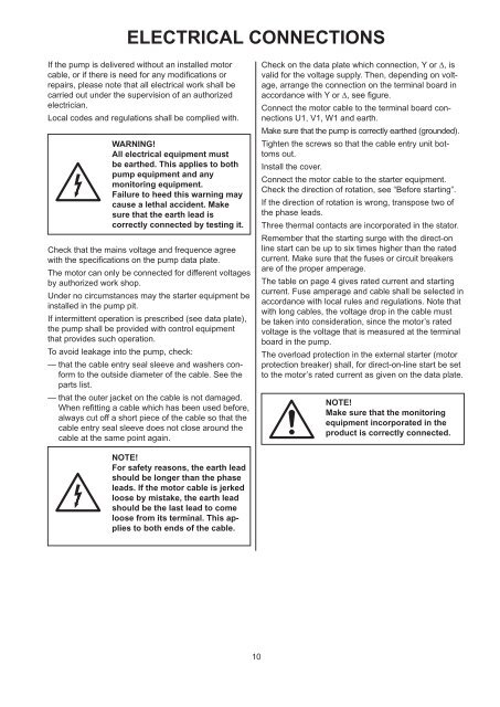
WARNING!<br />
All electrical equipment must<br />
be earthed. This applies to both<br />
pump equipment and any<br />
monitoring equipment.<br />
Failure to heed this warning may<br />
cause a lethal accident. Make<br />
sure that the earth lead is<br />
correctly connected by testing it.<br />
Check that the mains voltage and frequence agree<br />
with the specifications on the pump data plate.<br />
The motor can only be connected for different voltages<br />
by authorized work shop.<br />
Under no circumstances may the starter equipment be<br />
installed in the pump pit.<br />
If intermittent operation is prescribed (see data plate),<br />
the pump shall be provided with control equipment<br />
that provides such operation.<br />
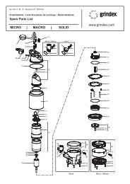
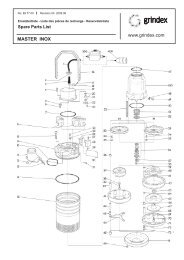
To avoid leakage into the pump, check:<br />
— that the cable entry seal sleeve and washers conform<br />
to the outside diameter of the cable. See the<br />
parts list.<br />
— that the outer jacket on the cable is not damaged.<br />
When refitting a cable which has been used before,<br />
always cut off a short piece of the cable so that the<br />
cable entry seal sleeve does not close around the<br />
cable at the same point again.<br />
NOTE!<br />
For safety reasons, the earth lead<br />
should be longer than the phase<br />
leads. If the motor cable is jerked<br />
loose by mis take, the earth lead<br />
should be the last lead to come<br />
loose from its terminal. This applies<br />
to both ends of the cable.<br />
10<br />
Check on the data plate which connection, Y or ∆, is<br />
valid for the voltage supply. Then, depending on voltage,<br />
arrange the connection on the terminal board in<br />
accordance with Y or ∆, see figure.<br />
Connect the motor cable to the terminal board connections<br />
U1, V1, W1 and earth.<br />
Make sure that the pump is correctly earthed (grounded).<br />
Tighten the screws so that the cable entry unit bottoms<br />
out.<br />
Install the cover.<br />
Connect the motor cable to the starter equipment.<br />
Check the direction of rotation, see “Before starting”.<br />
If the direction of rotation is wrong, transpose two of<br />
the phase leads.<br />
Three thermal contacts are incorporated in the stator.<br />
Remember that the starting surge with the direct-on<br />
line start can be up to six times higher than the rated<br />
current. Make sure that the fuses or circuit breakers<br />
are of the proper amperage.<br />
The table on page 4 gives rated current and starting<br />
current. Fuse amperage and cable shall be selected in<br />
accordance with local rules and regulations. Note that<br />
with long cables, the voltage drop in the cable must<br />
be taken into consideration, since the motor’s rated<br />
voltage is the voltage that is measured at the terminal<br />
board in the pump.<br />
The overload protection in the external starter (motor<br />
protection breaker) shall, for direct-on-line start be set<br />
to the motor’s rated current as given on the data plate.<br />
NOTE!<br />
Make sure that the monitoring<br />
equipment incorporated in the<br />
product is correctly connected.