FTTH DROP AND INDOOR CABLES - Draka Communications
FTTH DROP AND INDOOR CABLES - Draka Communications
FTTH DROP AND INDOOR CABLES - Draka Communications

Create successful ePaper yourself
Turn your PDF publications into a flip-book with our unique Google optimized e-Paper software.
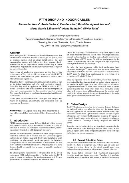
<strong>FTTH</strong> <strong>DROP</strong> <strong>AND</strong> <strong>INDOOR</strong> <strong>CABLES</strong><br />
Alexander Weiss 1 , Arnie Berkers², Eva Boncidai³, Knud Bundgaard Jen sen 4 ,<br />
Marta Garcia S.Emeterio 5 , Klaus Nothofer 5 , Olivier Tatat 6<br />
<strong>Draka</strong> Comteq Cable Solutions<br />
1 Moenchengladbach, Germany, ²Delfzijl, The Netherlands, ³Nuremberg, Germany,<br />
Abstract<br />
Since some years <strong>FTTH</strong> networks are installed in many areas. For<br />
<strong>FTTH</strong> outdoor installation different cable designs are applied, such<br />
as common outdoor duct or direct buried cables, but also<br />
indoor/outdoor designs with halogenfree flame retardent sheath.<br />
Most of them are too large to fit as small subscriber drop or indoor<br />
<strong>FTTH</strong> cables. Requirements for small drop cables with HFFR jacket<br />
are seen in the market.<br />
Being aware of challenging requirements on the field of fire<br />
performances of fiber optical cables, the selection of suitable HFFR<br />
materials has been made with special accuracy in order to fulfil<br />
relevant technical regulations.<br />
The cables shall be suitable as drop cables, subscriber cables as well<br />
as for indoor installation and offer high mechanical strength.<br />
Preferably they shall be applicable as <strong>FTTH</strong> as well as FTTD<br />
cables. The required fiber count is limited; in the first attempt max 4<br />
fibers were requested; except for the riser cable, which has a higher<br />
fiber count. Preferably no or just limited amount of gel shall be used<br />
in the designs.<br />
In this paper we describe different developed new designs. The<br />
results of mechanical, environmental and installation tests are<br />
presented and discussed.<br />
Keywords: <strong>FTTH</strong>, optical cable, drop cable, subscriber cable,<br />
riser cable, optical fiber, bend optimized fiber, flame retardent, fire<br />
test<br />
1. Introduction<br />
<strong>FTTH</strong> networks require many different kinds of cables, because<br />
such networks cover indoor and outdoor sections, but also the<br />
transition in between. To fulfil these requirements outdoor, indooroutdoor<br />
as well as indoor cable designs are necessary.<br />
Another fact to be taken into consideration is that a huge variety of<br />
installation methods are in practical use, too. Commonly applied<br />
technologies are (micro-) duct and direct buried installation, aerial<br />
installation, but also on-wall, inside and outside the buildings.<br />
In dependence of the local environment of the network the best<br />
suited installation methods are selected. Regarding this need cable<br />
designs should be suitable for as many as possible installation<br />
technologies.<br />
To address general requirements of fire protection set by law or<br />
customers a HFFR jacket is mandatory. The best suited the HFFR<br />
grade is chosen according to the local requirements and fire test<br />
specifications to ensure the requested fire protection level.<br />
4 Brøndby, Denmark, 5 Santander, Spain, 6 Calais, France<br />
+49-2166-134-1419 · alexander.weiss@draka.com<br />
Out of the large range of different cable designs this paper focuses<br />
on small subscriber drop and indoor cables with high mechanical<br />
strength and outstanding low bending radii. All cable constructions<br />
described have a HFFR sheath. To address requirements for dry<br />
cables a completely dry cable and designs with tight respectively<br />
semi-tight buffer tubes are presented.<br />
To offer the best achievable cable bend performance bend<br />
optimized BendBright XS® fibers were used for some cables, too.<br />
These fibers fulfil both, the ITU-T specifications G.652 class D and<br />
G.657 class A. Their bend performance is even better, it is<br />
according to ITU-T G.657 class B.<br />
They are especially suited for indoor cables, where their capability<br />
to withstand bends with exceptional low radius without increase in<br />
attenuation is highly appreciated and offers superior advantages<br />
compared to standard SM fibers, since installation routes of indoor<br />
cables frequently pass areas where small bends occur, like around<br />
edges and corners. As an additional advantage the possible small<br />
bend radius allows reduced size connection equipment, like quite<br />
small splice closures and termination boxes.<br />
2. Cable Design<br />
For <strong>FTTH</strong> networks as described above no cable design is dedicated<br />
or preferred, neither for subscriber drop nor for indoor cables.<br />
Different approaches are suitable like central, loose or (semi-) tight<br />
buffer tube constructions. Optional cable elements are tapes or yarns<br />
which may carry waterswellable materials in case a dry design is<br />
desired. Possible other cable elements are strength members or<br />
copper conductors. The design is finally completed with a HFFR<br />
sheath.<br />
Exemplary the following designs are described, a completely dry<br />
central tube drop cable, semi-tight buffered fiber cables, a riser<br />
cable, a zipcord cable and a composite subscriber cable with tight<br />
buffer tubes and copper conductors.<br />
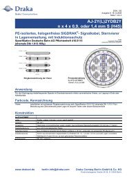
2.1 Central Tube Drop Cable<br />
The presented central tube drop cable consists of a HFFR tube and<br />
sheath. The tube is completely dry, without gels or yarns, just<br />
housing the optical fibers. In the sheath aramid yarns were<br />
embedded as strength elements. It has an outer diameter of 4 mm.<br />
The design fulfills extremely high mechanical requirements<br />
regarding crush and impact properties. Therefore it is perfectly<br />
suited for on-wall installation with staples. In parallel it is absolutely
free of gels. If needed, swellable materials can be added to get a<br />
watertight design.<br />
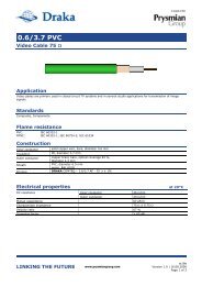
Both, standard ESMF fibers and bend optimized BendBright XS®<br />
fibers were tested in the design. Main difference between the two<br />
fiber types is, as expected, the behavior in bend test. Bend<br />
optimized fibers allow 10 mm minimum cable bend radius, whereas<br />
standard ESMF fibers allow only minimum 20 mm, which is<br />
approximately twice as low than of bend optimized fibers (figure 2).<br />
The absolute difference looks small, but the gain in practical safety<br />
margin is much bigger, especially since the cables are dedicated to<br />
installation environments, where such small bends frequently occur.<br />
To achieve a high level of flame retardency a highly flame retardent<br />
HFFR grade is necessary. Grades with LOI values up to<br />
approximately 40 are not sufficient to pass severe fire tests, because<br />
the empty inner tube acts like a chimney.<br />
Figure 1. Central Tube Drop Cable<br />
Table 1. Type Test Results<br />
test result<br />
crush test<br />
2000 N, plate-plate,<br />
100 mm, 15 min<br />
impact test<br />
10 Nm, 3 impacts,<br />
r = 300 mm<br />
pass<br />
pass<br />
comment<br />
BBXS ® fibers ESMF fibers<br />
0.04 dB,<br />
no damage<br />
0.00 dB,<br />
no damage<br />
0.02 dB,<br />
no damage<br />
0.00 dB,<br />
no damage<br />
temperature cycle test<br />
-5°C to +70°C pass 0.05 dB/km av 0.08 dB/km av<br />
bend test (RT)<br />
6 turns, 10 cycles pass<br />
Attenuation measured at 1550 nm.<br />
Change in<br />
Attenuation [dB]<br />
1,2<br />
1,0<br />
0,8<br />
0,6<br />
0,4<br />
0,2<br />
0,0<br />
Bend Test Result<br />
r = 10mm<br />
0.09 dB max<br />
r = 20mm<br />
0.08 dB max<br />
5 mm 10 mm 18 mm 20 mm 25 mm<br />
Bend Radius<br />
BBXS ESMF<br />
Attenuation measured at 1550 nm.<br />
Figure 2. Bend Test, ESMF versus BendBright XS® Fibers<br />
2.2 Dry Semi-Tight Design<br />
Dry semi-tight designs with one or two fibers are dedicated to<br />
subscriber indoor branching. Therefore, such cables are mainly<br />
installed on-wall by stapling or gluing.<br />
The single fiber cable is a 2.8 mm diameter construction, the cable<br />
with two fibers a 4.2 mm diameter construction. Both are based on<br />
900 µm semi-tight buffered fibers. In such a design the fiber is<br />
decoupled from the 900 μm buffer tube. This semi-tight<br />
construction guarantees easy end-access of the optical fibers over<br />
one meter in less than a minute.<br />
Both cables were made with bend optimized BendBright XS® fibers.<br />
In both cases a highly flame retardant HFFR was used, allowing to<br />
pass the vertical burner test according to EN50265-1.<br />
Cross sections of the cables and test results are shown below.<br />
Figure 3. Semi-Tight Buffered Designs<br />
Table 2. Type Test Results<br />
test result<br />
crush test<br />
1000 N, plate-plate,<br />
100 mm, 15 min<br />
impact test<br />
(RT and –5°C)<br />
3 Nm, 3 impacts,<br />
r = 300 mm<br />
pass<br />
pass<br />
single fiber<br />
design<br />
0.03 dB,<br />
no damage<br />
< 0.01 dB,<br />
no damage<br />
comment<br />
dual fiber<br />
design<br />
0.00 dB,<br />
no damage<br />
0.03 dB,<br />
no damage<br />
temperature cycle test<br />
-5°C to +60°C pass < 0.01 dB/km < 0.01 dB/km<br />
bend test (RT)<br />
6 turns, 10 cycles pass<br />
Attenuation measured at 1550 nm.<br />
r = 10mm<br />
0.13 dB<br />
r = 10mm<br />
0.04 dB<br />
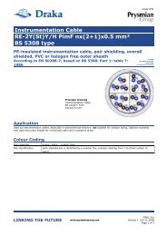
2.3 Riser Cable<br />
When there is a need to get many fibers to several distribution<br />
points or separate flats in different floors of a building, a riser<br />
design is chosen for the vertical installation. This cable has really<br />
low weight and size, something very important for a riser<br />
application. However, its main advantage in this case is the ability<br />
to segregate one or more bundles of fibers per flat, just by opening<br />
small windows of approximately 5 cm in length in the outer jacket.<br />
This could also allow termination of several fibers in a distribution<br />
box of a floor.<br />
The riser cable carries a maximum of 48 optical fibers in a 8x6<br />
configuration with several small semi-tight buffer tubes made of a<br />
soft material. These modules are loosely placed into the cable<br />
center, surrounded by some aramid yarns as strength elements and a
HFFR flame retardant jacket. The overall outer cable diameter is<br />
approximately 7.6 mm, the weight 50 kg/km.<br />
Figure 4. Riser Cable<br />
The riser cable has been mechanically and thermally tested in two<br />
versions, with standard ESMF fibers and with bend resistant fibers<br />
BendBright XS® . The results of the tests show, as expected, a better<br />
behavior of the bend-optimized fibers, even so both versions passed<br />
the targeted requirements. The most amazing difference has been<br />
found, as always, in the bend test, where the bend optimized fibers<br />
reach max change in attenuation of 0.02 dB for a mandrel of 10 mm<br />
radius. This test has been carried out on each module, since the<br />
complete cable cannot easily be bend in such small radius. The test<br />
is therefore even more severe. Table 3 shows a short summary of<br />
the main results.<br />
Table 3. Type Test Results<br />
test result<br />
crush test<br />
2000 N, plate-plate,<br />
100 mm, 15 min<br />
impact test<br />
5 Nm, 3 impacts,<br />
r = 300 mm<br />
pass<br />
pass<br />
comment<br />
BBXS ® fibers ESMF fibers<br />
0.04 dB<br />
no damage<br />
(reversible)<br />
0.00 dB,<br />
no damage<br />
1.5 dB (*)<br />
no damage<br />
(reversible)<br />
0.01 dB,<br />
no damage<br />
temperature cycle test<br />
-5°C to +60°C pass 0.05 dB/km Δα 0.10 dB/km av<br />
bend test (RT)<br />
6 turns, 10 cycles (on<br />
modules)<br />
pass<br />
r = 10 mm<br />
0.02 dB, max<br />
r = 20 mm<br />
1.0 dB max<br />
Attenuation measured at 1550 nm.<br />
(*) For information purposes only. The specification requested 1400 N<br />
load.<br />
The attenuation increase through processes during cable<br />
manufacturing showed a small difference depending on the fiber<br />
type, since the maximum change in attenuation was 0.01 dB/km (at<br />
both, 1550 nm and 1625 nm), for the BendBright XS® fibers and up<br />
to 0.02 dB/km for the ESMF fibers. This confirms that bendoptimized<br />
fibers can withstand higher stress on fibers during cabling<br />
process than standard ESMF fibers.<br />
2.4 Zipcord Cable<br />
Basically, the zipcord cable consists of 2 patchcords of 2.8mm<br />
outer diameter each. Each one is made of 900µm tight buffered<br />
tube surrounded by aramid yarns and a HFFR jacket. The zipcord<br />
is splittable into the two single fiber patchcords<br />
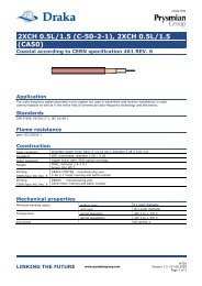
For a simple demonstration of the behavior of a BendBright XS®<br />
fiber in comparison with a standard ESMF fiber a zipcord cable<br />
having in each branch one fiber of the different fiber types<br />
became bend around a single sharp bend like shown in the picture<br />
below.<br />
Figure 5. Zipcord Cable<br />
Figure 6. Bend Test<br />
The measured loss during this test was 5.45 dB for the ESMF fiber<br />
and only 0.01 dB for the BendBright XS® fiber at 1550 nm.<br />
2.5 Composite Cable<br />
The presented composite cable consists of four transmission<br />
elements, two tight buffered BendBright XS® fibers and two<br />
insulated copper conductors, wrapped with a polyester non-woven<br />
tape, aramid yarns and a HFFR sheath. The cable has an outer<br />
diameter of 5.5 mm.<br />
This cable is designed for indoor use to connect an optical-electrical<br />
converter and supplying that equipment with power using just one<br />
cable.<br />
Figure 7. Composite Cable
Table 4. Type Test Results<br />
test result comment<br />
crush test<br />
3000 N, plate-plate,<br />
100 mm, 5 min<br />
pass<br />
0.00 dB<br />
temperature cycle test<br />
-30°C to +70°C pass 0.00 dB, 1550nm & 1625 nm<br />
bend test (RT)<br />
2 turns, 5 cycles,<br />
r = 10 mm<br />
pass<br />
0.01 dB, max<br />
bend test (RT)<br />
90° turn, r = 5 mm pass 0.01 dB, max<br />
Attenuation measured at 1550 nm, if not stated otherwise.<br />
3. Results of Installation and Fire tests<br />
3.1 Installation Tests<br />
3.1.1 Semi-Tight Design<br />
The dual fiber dry semi-tight subscriber cable was submitted to a<br />
stapling installation tests.<br />
The cable has been stapled against a wall, around a doorframe and<br />
around two support beams above the door as shown on the<br />
following scheme and pictures.<br />
A stapling gun was used, with round shaped staples.<br />
Figure 8. Test Setup with Door and Support Beams<br />
cable<br />
Figure 9. Installation around a Doorframe<br />
cable<br />
Figure 10. Installation around a Corner<br />
The installation path included 15 angles with 90° with relatively<br />
sharp bend radius as shown on the pictures; 89 staples were used.<br />
During the installation the attenuation was measured at 1550 nm.<br />
The attenuation change at the end of the test was 0.05 dB.<br />
Figure 11. Tacker, Staples and Cables<br />
3.1.2 Riser Cable<br />
For vertical installations in buildings the fiber units of the riser cable<br />
will be individually segregated on request to every subscriber. The<br />
use of BendBright XS® fibers allows to pass significantly smaller<br />
bends in the installation route as shown in the following picture.
Figure 12. Installation around a Corner<br />
3.1.3 Composite Cable<br />
The composite cable was installed on skirting passing four 90°<br />
corners using cable clips as shown in the picture. The resulting<br />
attenuation increase was only 0.01 dB at 1550 nm, so within the<br />
measurement accuracy of 0.05 dB.<br />
Figure 13. Installation around Corners<br />
3.2 Fire Tests<br />
Flame test requirement for the semi-tight drop cables described in<br />
section 2.2 was EN 50265-1. It turned out, that a standard HFFR<br />
compound with an LOI in the range of 37 to 40 was not suitable to<br />
always safely pass the test on the small cable designs with outer<br />
diameters below 5 mm.<br />
Usually indoor optical fiber cables with diameter ranging from<br />
8 mm and above only need a standard HFFR compound (LOI of<br />
about 35) for passing a single burner test.<br />
Compared to larger cables the low wall thickness of HFFR is key<br />
for this behavior.<br />
Therefore several HFFR materials were tested for making the one<br />
and two fiber dry semi-tight subscriber cables, having limit oxygen<br />
index (LOI) between 36 to 45.<br />
The target was to consistently pass five times in a row, an<br />
EN 50265-1 burner test both on the non-aged but also on an aged<br />
cable (accelerated aging 7 days 100°C).<br />
For small subscriber optical fiber cable, it appeared from our tests<br />
results that only a highly flame retardant material with a LOI of<br />
about 45 allowed to pass this test, especially for the two fiber cable.<br />
The test was not consistently passed with a material having a LOI of<br />
38. When the burner is stopped after one minute the flame<br />
sometimes continued to very slowly progress along the cable,<br />
reaching the top of the sample after 8 to 10 minutes. The sustained<br />
burning was due to the autocatalytic effect occurring in the flame<br />
retardant material, supported also by the tendency of hot gases to<br />
rise in vertical positioned cable, a chimney effect. As secondary<br />
impact, the structure of material got porous and friable allowing<br />
diffusion of hot vapours from the core through the outer sheath,<br />
maintaining a high temperature in the environment. All these<br />
undesired factors could be solved by using of high performance<br />
flame retardant material.<br />
Figure 14. Sample with Low LOI HFFR Compound<br />
Figure 15. Sample with High Performance HFFR<br />
Compound
4. Conclusions<br />
Different types of <strong>FTTH</strong> subscriber drop, indoor and riser cables<br />
were successfully developed. They are approved by many<br />
customers for different applications. In parallel to the cables some<br />
customers approved bend optimized fibers to benefit from their<br />
superior low bending radii.<br />
The presented cables are suitable for all applications of <strong>FTTH</strong><br />
subscriber drop, indoor and riser cables. The range of designs<br />
includes completely dry cables as well as designs with tight and<br />
semi tight buffer tubes and copper conductors.<br />
Their extended robustness allows on-wall installation with staples<br />
without damage to fibers and cables. The fire retardence behavior is<br />
also quite well, giving the possibility to install cables in fire<br />
restricted areas. However, it must be considered, that for small<br />
cables HFFR compounds with high LOI must be selected to pass<br />
fire tests.<br />
All cables can be equipped with standard ESMF fibers as well as<br />
with bend optimized fibers like BendBright XS® . Bend optimized<br />
fibers offer additional advantages, but no constraints in comparison<br />
with standard ESMF fibers. The presented BendBright XS® fulfil<br />
both, the ITU-T specifications G.652 class D and G.657 class A.<br />
Their bend performance is even better, it is according to ITU-T<br />
G.657 class B. Such bend optimized fibers allow bend radii of about<br />
10 mm for the cables and lead to cables, which are very insensitive<br />
regarding kinking and therefore perfectly suited for indoor<br />
installation where small bends frequently occur.<br />
The presented cables offer a complete range of <strong>FTTH</strong> cables,<br />
covering subscriber drop cables, indoor, indoor/outdoor applications<br />
as well as riser cables.<br />
5. References<br />
[1] K.Nothofer, “Indoor Cabling with Bend-Optimized Fibers”<br />
Proc. <strong>FTTH</strong> Council Europe 2007 Conference (2007).<br />
[2] Gerard Kuyt, Piet Matthijsse, Laurent Gasca, Louis-Anne de<br />
Montmorillon, Arnie Berkers, Mijndert Doorn, Klaus<br />
Nothofer, Alexander Weiss, “Bend-insensitive single mode<br />
fibers used in new cable designs ,” OC&I conference (2007).<br />
[3] M.Garcia, C.Cortines, "Easy-to-Split and Bend Resistant Fig-8<br />
Drop Cable for <strong>FTTH</strong> Applications", Proc 55 th IWCS (2006),<br />
5-10.<br />
6. Biographies<br />
Alexander Weiss obtained his<br />
D.Sc. in chemistry of the<br />
University of Tübingen in 1990.<br />
In the same year he joined AEG<br />
(now <strong>Draka</strong> Comteq). He held<br />
various management positions in<br />
manufacturing and development<br />
of optical fiber cables and is<br />
currently Manager Materials of<br />
<strong>Draka</strong> Comteq Cable Solutions<br />
EMEA in Moenchengladbach,<br />
Germany.<br />
E-mail: alexander.weiss@draka.com<br />
Arnie Berkers received his<br />
M.Sc. degree in Electrical<br />
Engineering in 1987. In the<br />
same year he joined <strong>Draka</strong><br />
Comteq Telecom, IJzerweg 2,<br />
9936 BM Delfzijl, The<br />
Netherlands. Today he is<br />
responsible for the development<br />
of fiber optic cables.<br />
E-mail: arnie.berkers@draka.com<br />
Eva Boncidai received her Dipl.<br />
Ing. Chem. degree in<br />
Technology of Organic<br />
Chemistry in 1982. Early career<br />
in the pharmaceutical industry,<br />
study of the stereoisomery of<br />
drugs. In 1986 she joined Philips<br />
(PKI), now <strong>Draka</strong> Comteq Cable<br />
Solutions EMEA, in Nuremberg<br />
Germany. Since then she is<br />
responsible for material<br />
development with focus on fire<br />
performances of materials and<br />
cables.<br />
E-mail: eva.boncidai@draka.com<br />
Knud Bundgaard Jensen<br />
received his M.Sc degree in<br />
Electrical Engineering and<br />
joined NKT in 1968. From 1975<br />
he worked with development of<br />
optical fibers and from 1986<br />
with optical fiber cables. Since<br />
1994 responsible for<br />
development of fiber optic<br />
cables in <strong>Draka</strong> Comteq<br />
Denmark in Brøndby.<br />
E-mail: knud.bundgaard@draka.com<br />
Marta Garcia S. Emeterio<br />
received her Masters degree in<br />
Physics (with a specialty in<br />
Microelectronics) in 1992, from<br />
the University of Cantabria<br />
(Spain). In 1994, she joined<br />
Alcatel Cable Iberica, now<br />
<strong>Draka</strong> Comteq, working as a<br />
Product Engineer. During 1997<br />
and 1998 she was as Project<br />
leader for the Design<br />
Technology Group of Alcatel’s<br />
Development Center (OFCCC)in Claremont, NC. Nowadays, she<br />
manages the Development Group of <strong>Draka</strong> Comteq Iberica, in<br />
Spain.<br />
E-mail: marta.garcia@draka.com
Klaus Nothofer (1956) received<br />
his Dipl.-Ing. degree in<br />
Telecommunications and joined<br />
AEG-Kabel (now <strong>Draka</strong><br />
Comteq) in 1981. From 1984 he<br />
held various management<br />
positions in O.F. cable<br />
manufacturing, development,<br />
and marketing in Alcatel Europe.<br />
He is now Manager<br />
Development and Engineering<br />
for Optical Fiber Cables in <strong>Draka</strong> Comteq Cable Solutions EMEA.<br />
E-mail: klaus.nothofer@draka.com<br />
Olivier Tatat received his<br />
Engineering degree with a<br />
specialty in Materials in 1982.<br />
In 1985, he joined Alcatel<br />
Cable France (now <strong>Draka</strong><br />
Comteq). He held several<br />
positions in France, USA and<br />
Germany in Materials and<br />
Optical Fiber Cable<br />
Development. Since 2001, he is<br />
leading the Development and<br />
Engineering Group of <strong>Draka</strong> Comteq France in Calais.<br />
E-mail: olivier.tatat@draka.com