Coupling Of EMI To Cables - Applied Electromagnetics Group ...
Coupling Of EMI To Cables - Applied Electromagnetics Group ...
Coupling Of EMI To Cables - Applied Electromagnetics Group ...

You also want an ePaper? Increase the reach of your titles
YUMPU automatically turns print PDFs into web optimized ePapers that Google loves.
Appendix G- <strong>Coupling</strong> <strong>Of</strong> <strong>EMI</strong> <strong>To</strong> <strong>Cables</strong>: Theory And Models G1<br />
Appendix G<br />
<strong>Coupling</strong> <strong>Of</strong> <strong>EMI</strong> <strong>To</strong> <strong>Cables</strong>: Theory And<br />
Models<br />
University <strong>Of</strong> York<br />
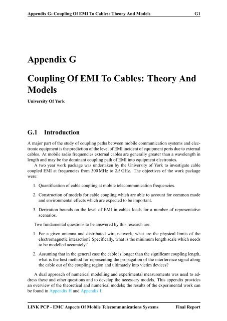
G.1 Introduction<br />
A major part of the study of coupling paths between mobile communication systems and electronic<br />
equipment is the prediction of the level of <strong>EMI</strong> incident of equipment ports due to external<br />
cables. At mobile radio frequencies external cables are generally greater than a wavelength in<br />
length and may be the dominant coupling path of <strong>EMI</strong> into equipment electronics.<br />
A two year work package was undertaken by the University of York to investigate cable<br />
coupled <strong>EMI</strong> at frequencies from 300 MHz to 2.5 GHz. The objectives of the work package<br />
were:<br />
1. Quantification of cable coupling at mobile telecommunication frequencies.<br />
2. Construction of models for cable coupling which are able to account for common mode<br />
and environmental effects which are expected to be important.<br />
3. Derivation bounds on the level of <strong>EMI</strong> in cables loads for a number of representative<br />
scenarios.<br />
Two fundamental questions to be answered by this research are:<br />
1. For a given antenna and distributed wire network, what are the physical limits of the<br />
electromagnetic interaction? Specifically, what is the minimum length scale which needs<br />
to be modelled accurately?<br />
2. Assuming that in the general case the cable is longer than the significant coupling length,<br />
what is the best method for representing the propagation of the interference signal along<br />
the cable out of the coupling region and ultimately into victim devices?<br />
A dual approach of numerical modelling and experimental measurements was used to address<br />
these and other questions and to develop the necessary models. This appendix provides<br />
an overview of the theoretical and numerical models; the results of the experimental work can<br />
be found in Appendix H and Appendix I.<br />
LINK PCP - EMC Aspects <strong>Of</strong> Mobile Telecommunications Systems Final Report
Appendix G- <strong>Coupling</strong> <strong>Of</strong> <strong>EMI</strong> <strong>To</strong> <strong>Cables</strong>: Theory And Models G2<br />
u<br />
v<br />
ξ<br />
<strong>To</strong>tal Common Differential<br />
i<br />
2<br />
i i<br />
i i<br />
c<br />
= +<br />
1 c d<br />
Figure G.1: Definition of differential and common mode currents on a twin wire cable.<br />
G.2 Basic Concepts<br />
An electromagnetic field incident on a cable induces currents on the cable conductors which<br />
may interfere with the signal currents leading to timing errors, data errors or even damage<br />
to the active components in the cable transceivers. In general the currents on a cable can be<br />
decomposed into two components - differential mode and common mode (see Figure G.1) [11].<br />
Consider a two conductor cable with currents i1(ξ, t) and i2(ξ, t) flowing on the two wires at<br />
distance ξ from one end of the cable. Writing:<br />
i1(ξ, t) = ic(ξ, t) + id(ξ, t) (G.1)<br />
i2(ξ, t) = ic(ξ, t) − id(ξ, t) (G.2)<br />
we can determine the differential mode current, id(ξ, t), and common mode current, ic(ξ, t), to<br />
be:<br />
id(ξ, t) = 1<br />
2 [i1(ξ, t) − i2(ξ, t)] (G.3)<br />
ic(ξ, t) = 1<br />
2 [i1(ξ, t) + i2(ξ, t)] (G.4)<br />
Thus at any cross-section of the cable the differential mode currents on the two wires are equal<br />
and opposite whereas the common mode currents are equal and in the same direction. The<br />
differential mode currents are almost always the functional currents responsible for carrying the<br />
signal along the cable. The differential mode currents can be approximated as giving rise to<br />
a transverse-electromagnetic wave (TEM) along the cable and hence predicted using standard<br />
transmission line theory. However, the common mode currents cannot in general be described<br />
by transmission line equations and must be predicted using other techniques. The presence of<br />
the common mode currents can be inferred by considering a scattering problem in which an EM<br />
field (E i , H i ) is incident on the cable giving rise to a scattered field (E s , H s ). The boundary<br />
condition on the surface of the cable conductors requires that the total tangential electric field<br />
vanishes:<br />
E i tan + E s tan = 0 (G.5)<br />
Since transmission line theory is based on TEM wave propagation, the differential mode currents<br />
it predicts can only produce a scattered field with E s tan = 0 and thus in general this method<br />
LINK PCP - EMC Aspects <strong>Of</strong> Mobile Telecommunications Systems Final Report<br />
i<br />
d
Appendix G- <strong>Coupling</strong> <strong>Of</strong> <strong>EMI</strong> <strong>To</strong> <strong>Cables</strong>: Theory And Models G3<br />
is not able to model the scattering of external fields. The common mode currents are required to<br />
provide the component of the scattered field which cancels the incident tangential field on the<br />
conductor surfaces.<br />
G.3 Transmission Line Theory<br />
G.3.1 Excited Transmission Line Theory<br />
The voltages and currents on a multi-conductor transmission line, within the approximations of<br />
standard transmission line theory, are governed by coupled partial differential equations [1, 5,<br />
11]. For the case of twin wire cables we can write the equations in the frequency domain as:<br />
∂vt (ξ, ω)<br />
+ zi(ξ, ω)<br />
∂ξ<br />
= vF (ξ, ω) (G.6)<br />
∂i(ξ, ω)<br />
∂ξ + yvt (ξ, ω) = iF (ξ, ω) (G.7)<br />
where the distributed impedance (z) and admittance (y) per unit length are<br />
z = r + jωl (G.8)<br />
y = g + jωc. (G.9)<br />
Here ξ measures the position along the cable, vt (ξ, ω) is the total voltage, i(ξ, ω) is the differential<br />
mode current, and l, c, r and g are respectively the inductance, capacitance, resistance<br />
and conductance per unit length of the cable. The driving terms are related to the incident<br />
electromagnetic field by:<br />
vF (ξ, ω) = jω<br />
s<br />
iF (ξ, ω) = −(g + jωc)<br />
0<br />
B i v(r, ω) du (G.10)<br />
s<br />
0<br />
E i u(r, ω) du (G.11)<br />
where û(ξ), ˆv(ξ) are unit vectors in the plane perpendicular to the cable at position ξ with û<br />
pointing towards the second wire (see Figure G.2). The integrations are in the plane transverse<br />
to the cable at position ξ and from one conductor to the other. The excited cable can thus be represented<br />
by an equivalent circuit as shown in Figure G.3 with distributed noise sources related to<br />
the incident fields [8]. The distributed voltage sources are due to the EMF of the magnetic flux<br />
between the two cable conductors and the current sources are due to the displacement current<br />
of the electric field driving between the wires.<br />
The complex propagation constant of the line, γ, and characteristic impedance, Zc, are given<br />
by [2]:<br />
γ = √ zy = α + jωβ (G.12)<br />
Zc = z/y (G.13)<br />
where β = 2π/λ is the wave number and α is the attenuation constant.<br />
The resistance per unit length, r, is due to the finite conductivity of the cable conductors<br />
and is a function of frequency due to the skin effect. The internal inductance of the wires also<br />
contributes to the total inductance per unit length. The conductance, g, is due to the dielectric<br />
LINK PCP - EMC Aspects <strong>Of</strong> Mobile Telecommunications Systems Final Report
Appendix G- <strong>Coupling</strong> <strong>Of</strong> <strong>EMI</strong> <strong>To</strong> <strong>Cables</strong>: Theory And Models G4<br />
transverse plane at ξ<br />
R<br />
S<br />
s<br />
ξ =0<br />
u<br />
v<br />
ξ<br />
d=2a<br />
R<br />
ξ =L<br />
L<br />
u<br />
ξ<br />
v<br />
λ<br />
+<br />
-<br />
i( ξ)<br />
v( ξ)<br />
E<br />
i( ξ)<br />
u<br />
B<br />
v<br />
ξ+ dξ<br />
Figure G.2: Excitation of a cable by an external electromagnetic field.<br />
loss of the medium surrounding the cable conductors. Signals on the cable are subject to these<br />
losses with an attenuation factor of [2, pp.90]<br />
α = r<br />
+<br />
2Zc<br />
gZc<br />
2<br />
(Np m −1 ) (G.14)<br />
The attenuation in decibels per metre is related to that in Nepers per metre by<br />
α (dB m −1 ) = 20 log 10 e × α (Np m −1 ) (G.15)<br />
≈ 8.686 α (Np m −1 ) (G.16)<br />
The formalism of this section can easily be extended to multi-wire transmission lines, see<br />
for example [8, 5].<br />
G.3.2 Parallel Wire Cable Parameters<br />
Unshielded parallel wire cables provide a worst case for direct differential mode coupling and<br />
were therefore used to provide an upper bound on this type of interference. The per unit length<br />
parameters of a parallel wire transmission line with conductors of conductivity σ in a medium<br />
with permittivity<br />
ɛ = ɛ ′ − jωɛ ′′ = ɛ ′ (1 − j tan δ) (G.17)<br />
LINK PCP - EMC Aspects <strong>Of</strong> Mobile Telecommunications Systems Final Report
Appendix G- <strong>Coupling</strong> <strong>Of</strong> <strong>EMI</strong> <strong>To</strong> <strong>Cables</strong>: Theory And Models G5<br />
u<br />
R S<br />
v ∼<br />
+<br />
s<br />
-<br />
v<br />
ξ<br />
T<br />
+<br />
ξ<br />
l dξ<br />
c dξ<br />
i( ξ+ dξ<br />
)<br />
v ( ξ ) T v ( ξ+ dξ<br />
)<br />
-<br />
i( ξ)<br />
and permeability µ are [2, pp.60]<br />
r dξ<br />
v ( ξ)dξ F<br />
+<br />
∼<br />
-<br />
g dξ<br />
i ( ξ)dξ F<br />
+<br />
-<br />
ξ+ d ξ<br />
Figure G.3: Equivalent circuit of an excited twin wire cable.<br />
c =<br />
πɛ<br />
cosh −1 (s/d)<br />
(G.18)<br />
l = µ<br />
π cosh−1 (s/d) (G.19)<br />
r = 2Rs<br />
πd<br />
g =<br />
≈ 2Rs<br />
πd<br />
<br />
πωɛ ′′<br />
cosh −1 (s/d)<br />
s/d<br />
(s/d) 2 − 1<br />
<br />
R L<br />
(G.20)<br />
(G.21)<br />
(G.22)<br />
where tan δ = ɛ ′′ /ɛ ′ is the loss tangent of the dielectric. Here Rs is the surface impedance of<br />
the cable conductors given by<br />
where δs is the skin depth<br />
Rs = 1<br />
δs =<br />
σδs<br />
=<br />
ωµ<br />
2σ<br />
(G.23)<br />
<br />
2<br />
. (G.24)<br />
ωµσ<br />
LINK PCP - EMC Aspects <strong>Of</strong> Mobile Telecommunications Systems Final Report
Appendix G- <strong>Coupling</strong> <strong>Of</strong> <strong>EMI</strong> <strong>To</strong> <strong>Cables</strong>: Theory And Models G6<br />
s d Zc ɛeff α (dBm −1 )<br />
(mm) (mm) (Ω) 100 MHz 1 GHz 2 GHz<br />
3 2 115 1 0.03 0.1 0.13<br />
6 2 212 1 0.017 0.05 0.08<br />
0.9 0.54 100 1.7 0.13 0.42 0.58<br />
Table G.1: Parallel wire cable parameters. The attenuation is calculated from (G.27) assuming<br />
the conductivity is that of copper.<br />
For low loss lines the characteristic impedance, wave number and attenuation constant are:<br />
Zc = η<br />
π cosh−1 β =<br />
(s/d)<br />
ω<br />
(G.25)<br />
µɛ ′<br />
= ω<br />
(G.26)<br />
α =<br />
vp<br />
ωµ<br />
2σ<br />
1<br />
πdZc<br />
+ π<br />
λ tan δ (Np m−1 ) (G.27)<br />
where vp = 1/ √ µɛ ′ is the phase velocity.<br />
Table G.1 shows the parameters for a number of parallel wire cables investigated during the<br />
project. The last entry corresponds to Category 5 (CAT-5) ethernet cable.<br />
The attenuation constants determined by these equations are only accurate at low frequencies.<br />
At high frequencies the cable loss is dominant by inhomogeneities in the cable construction<br />
giving much higher attenuation than those predicted by this simple model [3]. Measured<br />
differential mode attenuation data for CAT-5 UTP cables can be found in Appendix H. The loss<br />
at mobile telecommunication frequencies is typically over 10 dB m −1 .<br />
G.3.3 Solution For Short <strong>Cables</strong><br />
For an electrically short cable, L
Appendix G- <strong>Coupling</strong> <strong>Of</strong> <strong>EMI</strong> <strong>To</strong> <strong>Cables</strong>: Theory And Models G7<br />
H<br />
E<br />
k<br />
^<br />
endfire<br />
+<br />
v L<br />
F<br />
+ -<br />
~<br />
RS v i FL<br />
vL<br />
R<br />
S<br />
- -<br />
H<br />
k ^<br />
broadside<br />
Figure G.4: Equivalent circuit of an electrically short excited twin wire cable of length L.<br />
Consider the special case of end-fire illumination of a matched transmission line by a plane<br />
wave of magnitude E. If E is polarised in the u direction and hence H is in the v direction with<br />
magnitude H = E/η then it can be shown that<br />
E<br />
|vS(ω)| = 0 (G.32)<br />
|vL(ω)| = 2πfL<br />
Es<br />
c<br />
(G.33)<br />
assuming an air space cable. The voltage in the source load vanishes due to the cancellation<br />
of the contributions from the voltage and current sources. This effect is similar to the coupling<br />
of forward and backward waves in crosstalk between a pair of transmission lines [1, pp.492].<br />
The load voltage, vL, increases linearly with frequency as long as the cable remains electrically<br />
short. For illumination from the side of the cable (broad-side) the corresponding result is<br />
|vS(ω)| = πfL<br />
Es<br />
c<br />
(G.34)<br />
|vL(ω)| = πfL<br />
Es.<br />
c<br />
(G.35)<br />
In this case vS and vL must be equal due to symmetry and are half that of |vL| for end-fire<br />
illumination.<br />
LINK PCP - EMC Aspects <strong>Of</strong> Mobile Telecommunications Systems Final Report<br />
+<br />
L
Appendix G- <strong>Coupling</strong> <strong>Of</strong> <strong>EMI</strong> <strong>To</strong> <strong>Cables</strong>: Theory And Models G8<br />
G.3.4 General Solution<br />
The coupled transmission line equations (G.6) and (G.7) can be solved analytically using a<br />
chain matrix approach. The result is [4, 12]<br />
where<br />
i(ξ, ω) = Zc cosh γ(L − ξ) + ZL sinh γ(L − ξ)<br />
ZcD<br />
×<br />
ξ<br />
K(ξ<br />
0<br />
′ , ω) [Zc cosh γξ ′ + ZS sinh γξ ′ ] dξ ′<br />
+ Zc cosh γξ + ZS sinh γξ<br />
ZcD<br />
×<br />
L<br />
K(ξ<br />
ξ<br />
′ , ω) [Zc cosh γ(L − ξ ′ ) + ZL sinh γ(L − ξ ′ )] dξ ′<br />
s<br />
+ 1<br />
D [Zc cosh γ(L − ξ) + ZL sinh γ(L − ξ)]<br />
+ 1<br />
D [Zc cosh γξ + ZS sinh γξ]<br />
s<br />
0<br />
0<br />
E i u(u, 0, 0, ω) du<br />
E i u(u, 0, L, ω) du (G.36)<br />
K(ξ, ω) = E i ξ(s, 0, ξ, ω) − E i ξ(0, 0, ξ, ω) (G.37)<br />
D = (ZcZS + ZcZL) cosh γL + (Z 2 c + ZSZL) sinh γL. (G.38)<br />
The currents in the termination impedances can be determined by setting ξ = 0 and ξ = L<br />
in (G.36) to give:<br />
iS(ω) = i(0, ω)<br />
= 1<br />
s<br />
K(ξ, ω) [Zc cosh γ(L − ξ) + ZL sinh γ(L − ξ)] dξ<br />
D 0<br />
+ 1<br />
D [Zc<br />
s<br />
cosh γL + ZL sinh γL] E i u(u, 0, 0, ω) du<br />
− Zc<br />
s<br />
D 0<br />
E i u(u, 0, L, ω) du (G.39)<br />
iL(ω) =<br />
=<br />
i(L, ω)<br />
1<br />
−<br />
s<br />
K(ξ, ω) [Zc cosh γL + ZS sinh γL] dξ<br />
D 0<br />
1<br />
D [Zc<br />
s<br />
cosh γL + ZS sinh γL] E i u(u, 0, L, ω) du<br />
+ Zc<br />
D<br />
s<br />
and the corresponding terminal voltages are then<br />
The load voltages can be represented by transfer functions<br />
0<br />
0<br />
0<br />
E i u(u, 0, 0, ω) du (G.40)<br />
vS = iSZS (G.41)<br />
vL = iLZL. (G.42)<br />
TS,L = vS,L<br />
sEchar<br />
<br />
<br />
TS,L (dB) = 20 log <br />
10 <br />
vS,L<br />
sEchar<br />
<br />
<br />
<br />
<br />
(G.43)<br />
(G.44)<br />
LINK PCP - EMC Aspects <strong>Of</strong> Mobile Telecommunications Systems Final Report
Appendix G- <strong>Coupling</strong> <strong>Of</strong> <strong>EMI</strong> <strong>To</strong> <strong>Cables</strong>: Theory And Models G9<br />
where Echar is a characteristic field strength of the incident electromagnetic field. For example,<br />
for a plane wave we can take Echar equal to the amplitude of the electric field. For inhomogeneous<br />
electromagnetic fields such as that close to a dipole there is no simple choice for Echar.<br />
The maximum field strength incident on the cable is typically used.<br />
This solution was coded as a MATLAB program with a general plane wave incident field<br />
allowing for easy calculation of the transfer function. Figure G.5 shows the transfer function for<br />
a matched 5 m 115 Ω parallel wire cable (s = 1.5 mm, d = 2 mm) illuminated by a plane wave<br />
from the ξ = 0 (RS) end (end-fire illumination). The electric field is polarised in the u direction<br />
and the magnetic field in the v direction. At low frequencies, where the cable is electrically short<br />
the approxmation discussed in Section G.3.3 is valid and gives the low frequency asymptote<br />
shown in the figure. For this geometry and with match loads there is no voltage in the source<br />
load due to cancellation of the contributions from vF and iF .<br />
For broad-side illumination (Figure G.6) with the electric field along ξ and magnetic field<br />
along v the source and load voltages are the same due to symmetry. Note that for the end-fire<br />
illumination the first maximum in the transfer function corresponds to L = λ/4 whereas for<br />
broadside illumination the first maximum is at L = λ/2. The frequencies of maximum and<br />
minimum transfer are given by<br />
<br />
fmax = n + 1<br />
<br />
c<br />
(G.45)<br />
2 2L<br />
fmin = n c<br />
(G.46)<br />
2L<br />
for end-fire illumination and<br />
fmax = (2n + 1) c<br />
2L<br />
fmin = 2n c<br />
2L<br />
for broad-side illumination where n = 0, 1, 2, . . . .<br />
G.4 Common Mode Effects<br />
G.4.1 Image Theory<br />
(G.47)<br />
(G.48)<br />
<strong>To</strong> understand how common mode currents can be generated on a cable consider Figure G.7<br />
which shows a twin wire cable over an ideal ground plane excited by an incident field. We<br />
can replace this system using image theory with a four conductor system, the incident field and<br />
its image as shown. Providing the spacing between the wires in the original cable, s, is small<br />
compared to the height of the cable above ground, h, and the line is much longer than h we<br />
can replace each pair of conductors in the image system with a single conductor of radius s<br />
and we again have a two conductor line which is open circuited at each end and excited by<br />
the original field and its image. We can solve this problem using transmission line theory to<br />
give the differential mode current on the image conductors which are then interpreted as the<br />
common mode currents on the original cable conductors (assuming the current is distributed<br />
equally among the conductors of the original cable).<br />
Note that the effective noise sources driving the common mode current are integrals of<br />
the combined incident fields over a distance 2h >> s and hence the common mode currents<br />
induced on the cable are much greater than the differential mode currents. The superposition of<br />
LINK PCP - EMC Aspects <strong>Of</strong> Mobile Telecommunications Systems Final Report
Appendix G- <strong>Coupling</strong> <strong>Of</strong> <strong>EMI</strong> <strong>To</strong> <strong>Cables</strong>: Theory And Models G10<br />
Transfer Function, vL<br />
/(sE) (dB)<br />
20<br />
15<br />
10<br />
5<br />
0<br />
-5<br />
-10<br />
-15<br />
-20<br />
-25<br />
TL Theory<br />
Low Frequency Asymptote<br />
High Frequency Asymptote<br />
L=λ/4<br />
-30<br />
1e+06 1e+07 1e+08 1e+09<br />
Frequency (Hz)<br />
Figure G.5: .Transfer function for a match 5 m 115 Ω parallel wire line with end-fire plane<br />
wave illumination. The voltage in the source load is zero in this case due to cancellation of the<br />
contributions from vF and iF .<br />
Transfer Function, v S,L /(sE) (dB)<br />
20<br />
15<br />
10<br />
5<br />
0<br />
-5<br />
-10<br />
-15<br />
-20<br />
-25<br />
TL Theory<br />
Low Frequency Asymptote<br />
High Frequency Asymptote<br />
L=λ/2<br />
-30<br />
1e+06 1e+07 1e+08 1e+09<br />
Frequency (Hz)<br />
Figure G.6: Transfer functions for a match 5 m 115 Ω parallel wire line with broad-side plane<br />
wave illumination.<br />
LINK PCP - EMC Aspects <strong>Of</strong> Mobile Telecommunications Systems Final Report
Appendix G- <strong>Coupling</strong> <strong>Of</strong> <strong>EMI</strong> <strong>To</strong> <strong>Cables</strong>: Theory And Models G11<br />
E i<br />
Ground Plane<br />
E i<br />
image<br />
E i<br />
E i<br />
image<br />
Physical Situation Image Model Single Wire Model<br />
Figure G.7: Image theory model of common mode currents.<br />
the incident field and its image (i.e. ground reflections) will also create an interference pattern<br />
in the common mode currents.<br />
The attenuation of the common mode currents as they propagate along the cable is governed<br />
by the parameters of image problem and is in general much lower than that of the differential<br />
mode currents. However common mode currents are more efficiently re-radiated by the cable<br />
which results in higher attenuation than that predicted by the conductor loss alone. The proximity<br />
of the ground plane and presence of other metallic object provides guidance for the common<br />
mode currents reducing the radiation loss.<br />
Propagation of common mode currents on a cable is thus strongly dependent on the environment<br />
in which the cable is placed. Inhomogeneities, re-radiation and reflections all have a<br />
large impact on the propagation of the common mode currents. <strong>To</strong> predict the common mode<br />
currents on a real cable therefore requires a more detailed, full-wave, scattering analysis.<br />
G.4.2 Mode Conversion<br />
The presence of common mode currents on a cable does not in itself pose a threat to the integrity<br />
of the differential mode data signals. However if any mechanisms exist via which energy can be<br />
coupled from common mode into differential mode then the larger magnitudes of the common<br />
mode currents can result in this becoming the dominant <strong>EMI</strong> coupling path. The fundamental<br />
mechanism which gives rise to mode conversion is electrical or physical imbalance between the<br />
signal carrying conductors in a cable. Consider Figure G.8 which shows how imbalance in the<br />
termination of a twin wire line leads to mode conversion.<br />
The common mode currents ic are incident on a cable termination with resistance RL. If<br />
there are completely balanced return paths for the common mode currents (including capacitive<br />
and inductive effects) then there is no differential mode current through the load. However, if<br />
the impedance of the common mode return paths is different (Z1 = Z2) then a differential mode<br />
current can be generated through the load. The degree of imbalance between the return paths<br />
of the two wires determines the amount of common mode current which appears in the cable<br />
LINK PCP - EMC Aspects <strong>Of</strong> Mobile Telecommunications Systems Final Report<br />
E i
Appendix G- <strong>Coupling</strong> <strong>Of</strong> <strong>EMI</strong> <strong>To</strong> <strong>Cables</strong>: Theory And Models G12<br />
i c<br />
2i<br />
c<br />
Ground Plane<br />
i c<br />
Z<br />
1<br />
i d i -<br />
Z2 RL i c +<br />
Figure G.8: Schematic mode conversion mechanism at a cable termination.<br />
load. Thus any asymmetry between the two conductors on a two wire cable can lead to common<br />
mode currents affecting the data signals.<br />
Note that the imbalance can be caused by different capacitive and inductive couplings between<br />
the cable conductors and other conducting objects in the vicinity of the cable. The ground<br />
plane itself can cause imbalance on a parallel wire line if the conductors are one above the other<br />
relative to the ground.<br />
G.5 Frequency Domain Models<br />
G.5.1 Method <strong>Of</strong> Moments<br />
We are interested in modelling wired networks which are typically many wavelengths in size.<br />
The frequency domain integral equation method applied to thin wires provides an efficient solution<br />
for such structures. In view of our existing experience with the method of moments<br />
code NEC (Numerical Electromagnetic Code) this package was chosen as the initial modelling<br />
tool [13].<br />
In the moment method approach each wire in the system is divided into a number of short<br />
segments, each of which is typically chosen to be one tenth of a wavelength long. The total<br />
number of such segments in the model, Nseg, determines the CPU and memory requirements<br />
for the computation.<br />
Initially models were constructed for a simple parallel wire transmission line (PWTL) interacting<br />
with a half-wave dipole at 1GHz. This allowed validation of the results (at least for<br />
differential mode coupling) against the transmission line theory presented in Section G.3.4.<br />
Although superficially very simple the parallel wire transmission line shown in Figure G.9<br />
presents a number of important problems from a numerical modelling perspective. In the absence<br />
of any other external fields or structures the segment length along the wire may be made<br />
quite large; past experience suggests that a maximum length of ten times the wire separation<br />
may be used before the accuracy begins to deteriorate. However, it is the modelling of the end<br />
LINK PCP - EMC Aspects <strong>Of</strong> Mobile Telecommunications Systems Final Report<br />
i d<br />
c<br />
i d
Appendix G- <strong>Coupling</strong> <strong>Of</strong> <strong>EMI</strong> <strong>To</strong> <strong>Cables</strong>: Theory And Models G13<br />
s<br />
Figure G.9: Parallel wire transmission line model.<br />
Loaded<br />
Segment<br />
L<br />
d=2a<br />
Figure G.10: Detail of segmentation at the line end.<br />
terminations which is critical for attaining reasonable accuracy in the model.<br />
<strong>To</strong> model the terminating impedances two short wires, with diameters equal to those of the<br />
wires along the line, are connected across the line ends. These end wires must in general be<br />
divided into an odd number of segments 1, 3,. . . so that the central segments can be loaded with<br />
the required terminating impedances as shown in Figure G.10. It is found that having just one<br />
segment on the end wires, so that the loaded segment is in contact with the wires on the line at<br />
both of its ends, produces poor results. This indicates that at least three segments are required<br />
on the end wires. We also expect to have numerical problems if the segments at the ends of<br />
the short connecting wires lie completely ‘inside’ the wires on the transmission line, i.e. if the<br />
segment length is less than the wire radius. For three segments on the end wires this means<br />
that we must have s/a > 3 and therefore the minimum characteristic impedance which can be<br />
modelled by this method is about 115 Ω.<br />
A final consideration is the known problems which occurs with NEC if neighbouring segments<br />
have greatly differing lengths. The segment length of the transmission line wires at the<br />
LINK PCP - EMC Aspects <strong>Of</strong> Mobile Telecommunications Systems Final Report
Appendix G- <strong>Coupling</strong> <strong>Of</strong> <strong>EMI</strong> <strong>To</strong> <strong>Cables</strong>: Theory And Models G14<br />
ends of the line must therefore be commensurate with the segment length used on the terminating<br />
wires, i.e. about s/3. This indicates that dynamic segmentation will be needed to allow<br />
larger segment lengths to be used along the majority of the line where it would be very inefficient<br />
to use the same segmentation as the end wires.<br />
MATLAB programmes were written to provide a high level interface to NEC for generating<br />
dynamically segmented wire structures.<br />
G.5.2 Parallel Wire Models<br />
Two parallel wire lines where chosen for the initial study with characteristic impedances of<br />
115 ΩW and 212 Ω (see Table G.1). Recalling the discussion of the previous section the 115 Ω<br />
case is the minimum impedance line which we expect to be able to model accurately using this<br />
method.<br />
<strong>To</strong> assess the accuracy and stability of the modelling procedure the response of a matched<br />
1 1<br />
4<br />
wavelength 212 Ω cable to a 1 V excitation at one end, with matched loads at both ends, was<br />
investigated at 1 GHz. Figure G.11 shows the real and imaginary parts of the current obtained on<br />
the line for various segmentations compared with the known results from standard transmission<br />
line theory. Note that 40 uniform segments along each wire is not enough to give good accuracy<br />
in the real part of the current. This is due to the large difference in the segment lengths on the<br />
end wires and the neighbouring segments on the line wires. With dynamic segmentation many<br />
fewer segments are needed to obtain good accuracy. The slight translation of the numerical<br />
predictions for the imaginary part of the current relative to the theoretical curve is due end<br />
effects at the terminations.<br />
By looking at the magnitude of the current, which in theory should be constant, we determined<br />
the VSWR of the line due to residual (numerical) reflections from the terminations. We<br />
found that the VSWR was 1.06 which corresponds to a reflection coefficient of 3%. This can<br />
be regarded as a measure of the adequacy of the modelling of the end terminations. The results<br />
for the 115 Ω line were very similar with a slightly poorer VSWR of 1.13 (6% reflection).<br />
The pickup of interference on a twenty wavelength 212 Ω line excited by a nearby half-wave<br />
dipole was investigated at a frequency of 1 GHz with various orientations of the dipole relative<br />
to the line (see Figure G.12). For each orientation the dipole was positioned at a range of both<br />
one and three wavelengths from the transmission line and the current induced on the line (with<br />
a 1 V source on the dipole) was calculated.<br />
From the EMC point of view it is important to distinguish whether the induced current is in<br />
the differential-mode or common-mode. The results obtained for the 212 Ω line at a range of one<br />
wavelength show that for this geometry the pickup is generally in the common-mode, though<br />
in two cases the differential mode pickup is dominant. The results obtained are summarised in<br />
Table G.2.<br />
The differential mode current in configurations 5 and 8 can be predicted using the known<br />
solution of the excited transmission line equations G.36. Figure G.13 shows a comparison of the<br />
magnitude of the current for configuration 8 obtained from NEC with the theoretical solution<br />
using the far field approximation for the dipole fields. The good agreement gives us confidence<br />
in our modelling procedure. The region of significant coupling is also clearly identified.<br />
Now consider the common-mode currents. Referring to Table G.2 we see that in the configurations<br />
in which they are excited the common-mode currents are an order of magnitude<br />
greater than the differential mode currents in configurations 5 and 8; hence we can say that the<br />
pickup on a parallel wire transmission line in free space from a nearby dipole is generically in<br />
the common-mode. Note that in this model with simple terminating impedances the common-<br />
LINK PCP - EMC Aspects <strong>Of</strong> Mobile Telecommunications Systems Final Report
Appendix G- <strong>Coupling</strong> <strong>Of</strong> <strong>EMI</strong> <strong>To</strong> <strong>Cables</strong>: Theory And Models G15<br />
Real Part <strong>Of</strong> Current (mA)<br />
Imaginary Part <strong>Of</strong> Current (mA)<br />
2<br />
1<br />
0<br />
-1<br />
-2<br />
2<br />
1<br />
0<br />
-1<br />
-2<br />
0 0.2 0.4 0.6 0.8 1 1.2<br />
Position Along Wire (Wavelengths)<br />
Theory<br />
40 Uniform Segments<br />
63 Uniform Segments<br />
12 Dynaimic Segments<br />
0 0.2 0.4 0.6 0.8 1 1.2<br />
Position Along Wire (Wavelengths)<br />
Im(I) Theory<br />
40 Uniform Segments<br />
63 Segments<br />
12 Dynaimic Segments<br />
Figure G.11: Response of a one and a quarter wavelength 212 Ω parallel transmission line model<br />
to a 1 V excitation at the left hand end. The real and imaginary parts of the current along the<br />
cable are shown for uniform and dynamic segmentations compared to ideal transmission line<br />
theory.<br />
LINK PCP - EMC Aspects <strong>Of</strong> Mobile Telecommunications Systems Final Report
Appendix G- <strong>Coupling</strong> <strong>Of</strong> <strong>EMI</strong> <strong>To</strong> <strong>Cables</strong>: Theory And Models G16<br />
1.<br />
~<br />
~<br />
~<br />
2.<br />
4. 5.<br />
7.<br />
8.<br />
~<br />
Figure G.12: The nine geometrical orientations of the dipole relative to the transmission line<br />
investigated.<br />
mode component of the current cannot appear in the loads as there is no imbalance between<br />
the cable wires (the small load currents in configuration 3 are due to a small differential-mode<br />
current).<br />
The greatly differing magnitudes and forms of the current in each case highlights the importance<br />
of the geometrical orientation of the antenna relative to the transmission line.<br />
Figure G.14 shows the transfer function calculated from NEC for a 5 m 115 Ω cable 1 m<br />
above an ideal ground plane illuminated by the inhomogeneous field from a 1 GHz dipole compared<br />
to plane wave illumination. The plane wave transfer function is normalised to amplitude<br />
of the plane wave, Echar = 1 Vm −1 . The dipole transfer function is shown normalised to both<br />
Echar = Edipole(f) and Echar = Edipole(1 GHz) where Edipole(f) is the electric field strength<br />
of the dipole at 1 m. The result with Echar = Edipole(1 GHz) includes the antenna factor of<br />
the 1 GHz dipole whereas it is normalised out in the Echar = Edipole(f) transfer function. The<br />
result demonstrates that assuming a plane wave threat field can significantly over-estimate the<br />
threat coupled to cables by sources close to the cable.<br />
<strong>To</strong> summarise, the method of moments code NEC has been demonstrated to be a suitable<br />
tool for the analysis of an antenna interacting with a transmission line at frequencies up to<br />
1 GHz. The initial results show that both differential and common mode currents are excited<br />
on a parallel wire transmission line by a half-wave dipole placed at a range of one wavelength.<br />
Common mode pickup appears to be the more generic case, however the relative orientation of<br />
the dipole and transmission line is important for determining the mode, magnitude and form of<br />
LINK PCP - EMC Aspects <strong>Of</strong> Mobile Telecommunications Systems Final Report<br />
~<br />
~<br />
3.<br />
6.<br />
9.<br />
~<br />
~<br />
~<br />
z<br />
y<br />
x
Appendix G- <strong>Coupling</strong> <strong>Of</strong> <strong>EMI</strong> <strong>To</strong> <strong>Cables</strong>: Theory And Models G17<br />
Magnitude <strong>Of</strong> Differential Mode Current ( μA)<br />
35<br />
30<br />
25<br />
20<br />
15<br />
10<br />
5<br />
0<br />
Theory<br />
NEC<br />
0 5 10 15 20<br />
Position Along Wire (wavelengths)<br />
Figure G.13: Comparison of the differential mode current predicted by NEC and theory for<br />
configuration 8.<br />
Transfer Function, |vL<br />
/sEchar | (dB)<br />
10<br />
0<br />
-10<br />
-20<br />
-30<br />
-40<br />
Plane Wave, E char =1<br />
Dipole, E char =E dipole (1GHz)<br />
Dipole, E char =E dipole (f)<br />
-50<br />
300 400 500 600 700 800 900 1000<br />
Frequency (MHz)<br />
Figure G.14: Comparison of the transfer function of a 5 m cable under oblique incidence from<br />
both a plane wave and a 1 GHz half wave dipole.<br />
LINK PCP - EMC Aspects <strong>Of</strong> Mobile Telecommunications Systems Final Report
Appendix G- <strong>Coupling</strong> <strong>Of</strong> <strong>EMI</strong> <strong>To</strong> <strong>Cables</strong>: Theory And Models G18<br />
Configuration Dominant Left Load Right Load Maximum <strong>Coupling</strong><br />
Mode Current Current Current Length<br />
(µA) (µA) (µA) (λ)<br />
1 None - - - -<br />
2 Common 15.2 15.2 500 4<br />
3 Common 0.07 0.07 200 2<br />
4 Common 0 0 500 4<br />
5 Differentail 10.8 10.8 18 2<br />
6 Common 0 0 300 4<br />
7 None - - - -<br />
8 Differential 34.7 2.8 30 3<br />
9 Common 0 0 250 3<br />
Table G.2: Summary of the results obtained for the current in a 20 wavelength 212 Ω line excited<br />
by a dipole source at a range of one wavelength in the nine configurations considered.<br />
the induced current.<br />
G.5.3 Termination Models<br />
In the models so far the PWTL has been simply loaded with matched resistive termination to<br />
prevent reflections which might obscure our insight into the pickup on the cable. We now look<br />
at how the common-mode current propagates along the line and particularly how it is affected<br />
by the presence of metal enclosures and ground planes.<br />
In practice a PWTL carrying a signal into an enclosed device is usually attached to the box<br />
by some kind of connector. We will assume for now that the connector is such that one of the<br />
wires of the parallel pair sees a low impedance path onto the outer surface of the box whilst<br />
the other wire only sees the box through the load resistor. Under these conditions the box may<br />
be modelled in NEC by the geometry shown in Figure G.15. The short matching section is<br />
to allow the use a course segmentation of the metal box without introducing a rapid variation<br />
in segment lengths which can cause numerical problems. This model provides a worst case<br />
connector imbalance which can be used, together with the balanced termination, to bound the<br />
<strong>EMI</strong> in the cable loads for a given threat environment.<br />
G.5.4 Models With Mode Conversion<br />
Four different configurations were initially investigated with the unbalanced termination model.<br />
(see Figure G.16). In each case a 6 m (20 wavelengths at 1 GHz) 212 Ω PWTL was used with<br />
matched resistive terminations. Specifically the four cases are:<br />
A. Metal box on one end of the line<br />
B. Metal box on both ends of the line<br />
C. Line above a perfectly conducting ground plane<br />
D. Metal box on both ends above perfectly conducting ground plane<br />
LINK PCP - EMC Aspects <strong>Of</strong> Mobile Telecommunications Systems Final Report
Appendix G- <strong>Coupling</strong> <strong>Of</strong> <strong>EMI</strong> <strong>To</strong> <strong>Cables</strong>: Theory And Models G19<br />
Load<br />
Segment Matching<br />
Section<br />
Figure G.15: Geometry of the transmission line/box interface.<br />
Metal Box<br />
The metal boxes were modelled using a cubic wire frame in NEC with side lengths of 0.3 m,<br />
0.45 m and 0.6 m. A more realistic solid box was also considered using a second moment<br />
method code (CONCEPT). The antenna orientation and range was varied in the same way as<br />
for the free space model.<br />
In each case the important quantities are the differential and common mode currents incident<br />
on the resistive loads. As can be seen, with all the variables involved, the parameter space is<br />
very large and a subset of cases has to be considered. The following sections summarise the<br />
results obtained in each case.<br />
G.5.5 Case A - Box on one end of the line<br />
The presence of the metal box provides an alternative current path for the common-mode current<br />
away from the load, thus allowing common-mode to differential-mode conversion to occur at the<br />
interface between the transmission line and box . This is of crucial importance from an EMC<br />
perspective since it allows the electromagnetic energy to enter the load. In a more realistic<br />
model this will correspond to an electromagnetic interference (<strong>EMI</strong>) signal being able to get<br />
inside an enclosed device by coupling into external cables.<br />
The simulations were carried out at a frequency of 1 GHz with 1 V on the antenna for a<br />
variety of antenna orientations, ranges and box sizes. Table G.3 summarises the results obtained<br />
for three antenna orientations at a range of 0.3 m (1 wavelength at 1 GHz). The magnitude of<br />
the load currents at both ends are given as well as the maximum differential and common mode<br />
current on the line. In order to compare with a typical mobile phone note that multiplication by<br />
a factor of about 28 corresponds to 2 W radiated power from the dipole. Compared to the PWTL<br />
without the box attached we see that mode conversion has occurred resulting in <strong>EMI</strong> in the load<br />
resistor. The actual current distribution on the line is shown in Figure G.17 compared with that<br />
obtained with no box present. This clearly demonstrates the generation of the differential mode<br />
LINK PCP - EMC Aspects <strong>Of</strong> Mobile Telecommunications Systems Final Report
Appendix G- <strong>Coupling</strong> <strong>Of</strong> <strong>EMI</strong> <strong>To</strong> <strong>Cables</strong>: Theory And Models G20<br />
Case A: Case B:<br />
Case C:<br />
Case D:<br />
Figure G.16: Configurations investigated for the PWTL model with unbalanced terminations.<br />
Current Magnitude (microamps)<br />
350<br />
300<br />
250<br />
200<br />
150<br />
100<br />
50<br />
DM, no box<br />
CM, no box<br />
DM, with box<br />
CM, with box<br />
Box End<br />
0<br />
-10 -8 -6 -4 -2 0 2 4 6 8 10<br />
Position Along Line (wavelengths)<br />
Figure G.17: Differential and common mode currents induced on a PWTL in configuration 6<br />
with and without the box at the right hand end.<br />
LINK PCP - EMC Aspects <strong>Of</strong> Mobile Telecommunications Systems Final Report
Appendix G- <strong>Coupling</strong> <strong>Of</strong> <strong>EMI</strong> <strong>To</strong> <strong>Cables</strong>: Theory And Models G21<br />
Antenna Free End Box End Maximum Maximum<br />
Orientation Load Current Load Current DM Current CM Current<br />
µA (µA) (µA) (µA)<br />
3 4.8 4.5 78.8 316<br />
5 9.4 9.2 22.9 12.9<br />
6 5.3 5.1 5.6 317<br />
Table G.3: Summary of results for Case A. The magnitude of the current in each load is given<br />
together with the maximum differential-mode (DM) and common-mode (CM) currents on the<br />
line.<br />
current by the presence of the box. Note that the differential mode current also propagates to<br />
the other end of the line and appears in the load not connected to the box. This highlights the<br />
potential risk to shielded devices from <strong>EMI</strong> due to coupling into external cables.<br />
Results from other configurations show essentially the same form of behaviour. Note that<br />
mode conversion in the opposite direction is also possible. For example, with the antenna in<br />
configuration 5 the pickup on the PWTL is in the differential mode when the box is not present,<br />
however with the box in place we see a common mode component in the current induced on the<br />
line.<br />
G.5.6 Case B - Box on both ends of the line<br />
This case shows no important new features compared to case A. It should be noted however that<br />
the differential mode current on the line now tends to appear as a standing wave with a high<br />
VSWR since both ends of the line now launch a differential mode current wave along the line.<br />
The magnitude of the differential mode current tends to be higher than with just one box on the<br />
line, but the amount of this current appearing in the load depends on the length of the line - i.e.<br />
where in the standing wave pattern the load is located.<br />
G.5.7 Case C - Ground plane<br />
The placing of a perfectly conducting ground plane below the transmission line and dipole antenna<br />
has a significant effect on the current induced on the cable. The system can be simulated<br />
directly using NEC giving the currents shown in Figure G.18 for configuration 6 with a ground<br />
plane 0.8 m below the transmission line. <strong>To</strong> aid interpretation of the results it is useful to consider<br />
the equivalent image problem consisting of the images of both the PWTL and dipole in the<br />
ground plane. Since common-mode pickup is usually dominant we can replace the PWTL by<br />
a single wire with some effective radius so that the image system contains a new PWTL with a<br />
very large wire separation (twice the height of the original PWTL above the ground plane) and<br />
two dipole antennas. The nulls in the common-mode current shown in Figure G.18 can then be<br />
attributed to the destructive interference of the fields from the two dipoles. Such a configuration<br />
can in fact be solved theoretical using the same method as was used for the differential mode<br />
currents on a free space PWTL. This method is however incapable of accounting for differential<br />
mode currents which can also be induced on the line or caused by mode conversion.<br />
LINK PCP - EMC Aspects <strong>Of</strong> Mobile Telecommunications Systems Final Report
Appendix G- <strong>Coupling</strong> <strong>Of</strong> <strong>EMI</strong> <strong>To</strong> <strong>Cables</strong>: Theory And Models G22<br />
Current Magnitude (microamps)<br />
400<br />
350<br />
300<br />
250<br />
200<br />
150<br />
100<br />
50<br />
DM, no ground plane<br />
CM, no ground plane<br />
DM, with ground plane<br />
CM, with ground plane<br />
0<br />
-10 -8 -6 -4 -2 0 2 4 6 8 10<br />
Position Along Wire (wavelengths)<br />
Figure G.18: Differential and common mode currents induced on a PWTL in configuration 6<br />
with and without a ground plane 0.8 m below the line.<br />
Current Magnitude (microamps)<br />
400<br />
350<br />
300<br />
250<br />
200<br />
150<br />
100<br />
50<br />
DM, no boxes or ground plane<br />
CM, no boxes or ground plane<br />
DM, with boxes and ground plane<br />
CM, with boxes and ground plane<br />
0<br />
-10 -8 -6 -4 -2 0 2 4 6 8 10<br />
Position Along Wire (wavelengths)<br />
Figure G.19: Differential and common mode currents induced on a PWTL in configuration 6<br />
with and without the box at the right hand end and a ground plane 0.8 m below the line.<br />
LINK PCP - EMC Aspects <strong>Of</strong> Mobile Telecommunications Systems Final Report
Appendix G- <strong>Coupling</strong> <strong>Of</strong> <strong>EMI</strong> <strong>To</strong> <strong>Cables</strong>: Theory And Models G23<br />
Perfect Ground<br />
1m<br />
0.3m Cubic Box<br />
2m<br />
x<br />
z<br />
1m<br />
1.5m<br />
Source<br />
y<br />
2m<br />
Figure G.20: Typical scenario.<br />
G.5.8 Case D - Ground plane and box on each end of the line<br />
Placing boxes on each end of the line causes mode conversion in much the same way as when<br />
the ground plane is not present (see Figure G.19). Note the large differential-mode current<br />
(with a high VSWR) produced by the presence of the two boxes, much larger than that which is<br />
produced without the ground plane present. This illustrates the importance of reflections from<br />
nearby conducting surfaces in determining the threat from <strong>EMI</strong> coupling into cables.<br />
G.6 Scenario Models<br />
The geometry for a typical scenario is shown in Figure G.20. It consists of a cable of length 5 m<br />
running around a corner 1 m above a perfect ground plane. One end of the cable is attached to<br />
a 0.3 m cubic box which is modelled as a wire grid. The figure shows a single dipole source at<br />
a range of 1.5 m from the midpoint of the longest part of the cable.<br />
Initial simulations were carried out with NEC using a wire grid model for the box. Other<br />
simulations were done with CONCEPT using both a wire grid and surface patches. This allowed<br />
the effect of modelling approximations to be assessed. The common-mode current induced on<br />
the surface of the cable (which is insensitive to the type of cable used) is shown in Figure G.21<br />
and Figure G.22. As can be seen good agreement between NEC and CONCEPT is obtained<br />
both with the wire-grid and surface patch models.<br />
Transfer functions were then calculated for the same geometry but with three sources distributed<br />
as shown in Figure G.23. Source 1 is the same as in Figure G.20. This was done using<br />
the wire-grid model in NEC for frequencies in the GSM band 880-920 MHz. For each source<br />
the simulation is run over the frequency range of interest with unit voltage on the source. The<br />
other sources are short circuited and not excited. The load current and hence voltage in each<br />
load (two in this case) are determined. In the following Tji will be used to denote the voltage<br />
induced in load j due to the signal from source i, i.e. it is a voltage transfer function through the<br />
system from the mobile source to the victim device. The results presented here are for a 115 Ω<br />
unshielded parallel-wire transmission line with matched loads at each end. This is expected to<br />
be a worst case for interference pickup amongst the cables considered.<br />
The results for the two loads are shown in Figure G.24 and Figure G.25. The variation of the<br />
transfer function with frequency shows that a frequency resolution of around 2 MHz at 1 GHz<br />
LINK PCP - EMC Aspects <strong>Of</strong> Mobile Telecommunications Systems Final Report
Appendix G- <strong>Coupling</strong> <strong>Of</strong> <strong>EMI</strong> <strong>To</strong> <strong>Cables</strong>: Theory And Models G24<br />
NEC v Concept: Dipole, cable and box<br />
-20<br />
Concept - patch model<br />
NEC - wire grid model<br />
-25<br />
-30<br />
μA)<br />
-35<br />
Current magnitude (dB<br />
Figure G.21: Magnitude of common-mode current induced on cable.<br />
-40<br />
-45<br />
-50<br />
0 0.5 1 1.5 2 2.5 3 3.5 4 4.5 5<br />
Position along cable (m)<br />
LINK PCP - EMC Aspects <strong>Of</strong> Mobile Telecommunications Systems Final Report
Appendix G- <strong>Coupling</strong> <strong>Of</strong> <strong>EMI</strong> <strong>To</strong> <strong>Cables</strong>: Theory And Models G25<br />
NEC v Concept: Dipole, cable and box<br />
Concept - patch model<br />
NEC - wire grid model<br />
200<br />
150<br />
100<br />
50<br />
o )<br />
0<br />
Current phase (<br />
-50<br />
-100<br />
-150<br />
Figure G.22: Phase of common-mode current induced on cable.<br />
-200<br />
0 0.5 1 1.5 2 2.5 3 3.5 4 4.5 5<br />
Position along cable (m)<br />
LINK PCP - EMC Aspects <strong>Of</strong> Mobile Telecommunications Systems Final Report
Appendix G- <strong>Coupling</strong> <strong>Of</strong> <strong>EMI</strong> <strong>To</strong> <strong>Cables</strong>: Theory And Models G26<br />
2<br />
1.5<br />
1<br />
0.5<br />
0<br />
-4<br />
-2<br />
0<br />
2<br />
4<br />
-4<br />
Figure G.23: Location of sources for transfer function calculation.<br />
is appropriate for the EM simulations. Note that for the dipole sources used in the simulations<br />
an input voltage of around 28 V leads to a radiated power of about 2 W. This is the maximum<br />
radiated power for most hand-held phones. This shows that signals with magnitudes of the order<br />
of 50 mV are possible for the given geometry.<br />
G.7 <strong>Cables</strong> As Distributed Antennas<br />
From the perspective of pickup of interference a cable can be considered as a distributed antenna.<br />
The signal generated at the load terminals is the superposition of many elemental sources<br />
distributed along the cable. Considering the input terminals of a radio source and the output terminals<br />
of a cable as a radio propagation channel the effect of the distributed coupling of energy<br />
into the cable is similar to multipath propagation in a normal radio channel. This results in time<br />
dispersion of the signal from the radio source as observed in the cable loads. The amount of dispersion<br />
is dependent on the relative geometry of the source and cable and the cable propagation<br />
parameters.<br />
Figure G.26 illustrates a single radio source at position rj coupling to a cable which runs<br />
from rS to rL by some path. The total dispersion time, TD, of the signal observed in the load at<br />
rS can be written as:<br />
TD =<br />
|rL − rj|<br />
c<br />
-2<br />
+ L<br />
<br />
−<br />
vp<br />
|rS − rj|<br />
c<br />
= |rL − rj| − |rS − rj|<br />
c<br />
0<br />
+ L<br />
vp<br />
2<br />
4<br />
(G.49)<br />
LINK PCP - EMC Aspects <strong>Of</strong> Mobile Telecommunications Systems Final Report
Appendix G- <strong>Coupling</strong> <strong>Of</strong> <strong>EMI</strong> <strong>To</strong> <strong>Cables</strong>: Theory And Models G27<br />
Magnitude of Transfer Funcition<br />
o<br />
Phase of Transfer Funcition ( )<br />
0.0014<br />
0.0012<br />
0.001<br />
0.0008<br />
0.0006<br />
0.0004<br />
0.0002<br />
200<br />
150<br />
100<br />
50<br />
0<br />
-50<br />
-100<br />
-150<br />
Test Geometry: Near sources , load 1<br />
0<br />
880 885 890 895 900 905 910 915 920<br />
Frequency (MHz)<br />
Test Geometry: Near sources , load 1<br />
-200<br />
880 885 890 895 900 905 910 915 920<br />
Frequency (MHz)<br />
Figure G.24: The magnitude and phase of the transfer function for load 1.<br />
LINK PCP - EMC Aspects <strong>Of</strong> Mobile Telecommunications Systems Final Report<br />
T11<br />
T12<br />
T13<br />
T11<br />
T12<br />
T13
Appendix G- <strong>Coupling</strong> <strong>Of</strong> <strong>EMI</strong> <strong>To</strong> <strong>Cables</strong>: Theory And Models G28<br />
Magnitude of Transfer Funcition<br />
o<br />
Phase of Transfer Funcition ( )<br />
0.0014<br />
0.0012<br />
0.001<br />
0.0008<br />
0.0006<br />
0.0004<br />
0.0002<br />
200<br />
150<br />
100<br />
50<br />
0<br />
-50<br />
-100<br />
-150<br />
Test Geometry: Near sources , load 1<br />
0<br />
880 885 890 895 900 905 910 915 920<br />
Frequency (MHz)<br />
Test Geometry: Near sources , load 1<br />
-200<br />
880 885 890 895 900 905 910 915 920<br />
Frequency (MHz)<br />
Figure G.25: The magnitude and phase of the transfer function for load 2.<br />
LINK PCP - EMC Aspects <strong>Of</strong> Mobile Telecommunications Systems Final Report<br />
T11<br />
T12<br />
T13<br />
T11<br />
T12<br />
T13
Appendix G- <strong>Coupling</strong> <strong>Of</strong> <strong>EMI</strong> <strong>To</strong> <strong>Cables</strong>: Theory And Models G29<br />
Source<br />
End<br />
r S<br />
r S-<br />
r j<br />
Cable<br />
x<br />
z<br />
r j<br />
y<br />
Radio<br />
Source<br />
r L<br />
r - rj Figure G.26: Time dispersion due to distributed pickup.<br />
L<br />
Load<br />
End<br />
where c and vp are the velocity of light in free space and on the cable respectively and L is the<br />
total cable length. Since<br />
the time dispersion can be bounded by<br />
Hence the coherence bandwidth of the system is<br />
0 ≤ |rL − rj| − |rS − rj| ≤ L (G.50)<br />
L<br />
≥ L<br />
c<br />
(G.51)<br />
L<br />
vp<br />
fcoherence<br />
vp<br />
≤ TD ≤ 2L<br />
. (G.52)<br />
def 1<br />
≡<br />
TD<br />
vp<br />
= vp<br />
2L<br />
≈ c<br />
. (G.53)<br />
2L<br />
The interaction of a radio source with the cable can only be considered narrow band if the<br />
bandwidth of the source is much smaller than this coherence bandwidth, that is if<br />
fsource
Appendix G- <strong>Coupling</strong> <strong>Of</strong> <strong>EMI</strong> <strong>To</strong> <strong>Cables</strong>: Theory And Models G30<br />
System Channel System Channel System<br />
Bandwidth Bandwidth Coherence Length Coherence Length<br />
(kHz) (MHz) (m) (m)<br />
TETRA 25 20 600 0.75<br />
GSM900 200 25 75 0.60<br />
PCN1800 200 40 75 0.38<br />
DECT 1728 18 8.7 0.83<br />
UMTS 5000 20 3 0.75<br />
Table G.4: Maximum length of cable for coherent load signals.<br />
G.8 Time Domain Models<br />
G.8.1 FDTD Solution<br />
The excited transmission line equations (G.6) and (G.7) in the time domain are<br />
∂vt (ξ, t) ∂i(ξ, t)<br />
+ l<br />
∂ξ ∂t + ri(ξ, t) = vF (ξ, t) (G.55)<br />
∂i(ξ, t)<br />
∂ξ + c∂vt (ξ, t)<br />
+ gv<br />
∂t<br />
t (ξ, t) = iF (ξ, t) (G.56)<br />
where we have assumed that the loss terms r and g are independent of frequency. This approximation<br />
can be removed at the expense of complex convolution terms in the FDTD equations [6].<br />
The excitation terms are now<br />
s<br />
vF (ξ, t) = ∂<br />
B<br />
∂t 0<br />
i v(r, t) du (G.57)<br />
<br />
iF (ξ, t) = − g + c ∂<br />
s<br />
E<br />
∂t<br />
i u(r, t) du. (G.58)<br />
The numerical solution of these equations can be made more efficient by using the scattered<br />
field approach [5] in which the total voltage v t is replaced by the scattered voltage v s defined<br />
by<br />
0<br />
v t (ξ, t) = v s (ξ, t) + v i (ξ, t) (G.59)<br />
s<br />
= v s (ξ, t) −<br />
0<br />
E i u(u, 0, ξ, t) du (G.60)<br />
where v i (t) is the incident voltage. The coupled transmission line equations for the scattered<br />
voltage and current can then be written<br />
∂vs (ξ, t) ∂i(ξ, t)<br />
+ l<br />
∂ξ ∂t + ri(ξ, t) = vs F (ξ, t) (G.61)<br />
∂i(ξ, t)<br />
∂ξ + c∂vs (ξ, t)<br />
+ gv<br />
∂t<br />
s (ξ, t) = 0 (G.62)<br />
where the excitation term for the first equation is<br />
v s F (ξ, t) = E i ξ(s, 0, ξ, t) − E i ξ(0, 0, ξ, t). (G.63)<br />
LINK PCP - EMC Aspects <strong>Of</strong> Mobile Telecommunications Systems Final Report
Appendix G- <strong>Coupling</strong> <strong>Of</strong> <strong>EMI</strong> <strong>To</strong> <strong>Cables</strong>: Theory And Models G31<br />
R S<br />
v<br />
S<br />
i i i i i<br />
S 1<br />
N L<br />
m<br />
m m m m<br />
k<br />
n<br />
v<br />
1<br />
+ + + + +<br />
+ +<br />
+<br />
n<br />
v<br />
k<br />
n<br />
v<br />
N +1<br />
λ<br />
~ -<br />
-<br />
- ~<br />
v<br />
u<br />
+ + + + +<br />
ξ<br />
Δ<br />
ξ<br />
+<br />
voltage mesh point<br />
current mesh point<br />
Figure G.27: Space time discretisation of the transmission line using the leapfrog method.<br />
There is no excitation term for the second equation in this formulation which significantly reduces<br />
the computational time needed to solve the equations providing the total voltage is only<br />
observed at a few points along the cable.<br />
The equations are discretised by dividing the cable into uniform interlaced current and voltage<br />
meshes to give second order accuracy (see Figure G.27). The current is calculated at Nξ<br />
points ξ = (k − 1/2)/∆ξ (k = 1, . . . , Nξ) where ∆ξ = L/Nξ and the voltage at Nξ + 1 points<br />
ξ = (k − 1)/∆ξ (k = 1, . . . , Nξ + 1). Time is similarly discretised into Nt segments of length<br />
∆t.<br />
Defining the voltages and currents by<br />
v n k = v s ((k − 1)∆ξ, n∆t) (k = 1, . . . , Nξ + 1) (G.64)<br />
i n k = i ((k − 1/2)∆ξ, n∆t) (k = 1, . . . , Nξ) (G.65)<br />
v n F,k = v s F ((k − 1)∆ξ, n∆t) (k = 1, . . . , Nξ + 1) (G.66)<br />
the transmission line equations can be written<br />
l∆ξ<br />
∆t<br />
c∆ξ<br />
∆t<br />
+ r∆ξ<br />
2<br />
<br />
i n+3/2<br />
k<br />
<br />
g∆ξ<br />
+ v<br />
2<br />
n+1<br />
k<br />
<br />
l∆ξ<br />
=<br />
∆t<br />
+ ∆ξ<br />
<br />
c∆ξ<br />
=<br />
∆t<br />
<br />
r∆ξ<br />
− i<br />
2<br />
n+1/2<br />
k − v n+1<br />
k+1 + vn+1<br />
k<br />
2 (vn+3/2<br />
F,k + vn+1/2<br />
− g∆ξ<br />
2<br />
λ<br />
R<br />
F,k ) (G.67)<br />
<br />
v n k − i n+1/2<br />
k + i n+1/2<br />
k−1<br />
L<br />
v<br />
L<br />
(G.68)<br />
using second order central differences [6]. <strong>To</strong> incorporate the terminal constraints the transmission<br />
line equations must be discretised differently at the source and load points since the<br />
boundary conditions relate the current and voltage at the same place and time. When this is<br />
LINK PCP - EMC Aspects <strong>Of</strong> Mobile Telecommunications Systems Final Report
Appendix G- <strong>Coupling</strong> <strong>Of</strong> <strong>EMI</strong> <strong>To</strong> <strong>Cables</strong>: Theory And Models G32<br />
i n+1/2<br />
k-1<br />
v n+1<br />
k<br />
Δ<br />
ξ<br />
v n<br />
k<br />
i n+3/2<br />
k<br />
Δ t + + + + +<br />
t<br />
ξ<br />
i n+1/2<br />
k<br />
v n+1<br />
k+1<br />
+ + + + +<br />
Figure G.28: Update chart for the voltage and current meshes.<br />
done for the Thévenin source and load constraints<br />
v t 1(t) = v s S(t) + v i S(t)<br />
= vS(t) − RSiS(t) (G.69)<br />
v t Nξ+1(t) = v s L(t) + v i L(t)<br />
= vL(t) + RLiL(t) (G.70)<br />
we get the following equations for updating the voltage at the end points:<br />
<br />
RSc∆ξ RSg∆ξ<br />
+ +<br />
2∆t 4<br />
1<br />
<br />
v<br />
2<br />
n+1<br />
1 =<br />
<br />
RSc∆ξ RSg∆ξ<br />
− −<br />
2∆t 4<br />
1<br />
<br />
v<br />
2<br />
n 1<br />
− RSi n+1/2<br />
1 + 1 n+1<br />
vS 2<br />
+ vn −<br />
<br />
S<br />
1 i,n+1<br />
vS + v<br />
2<br />
i,n<br />
+<br />
<br />
S<br />
RS∆ξ n+1<br />
iF,1 4<br />
+ in <br />
RLc∆ξ RLg∆ξ<br />
+ +<br />
2∆t 4<br />
<br />
F,1<br />
1<br />
<br />
v<br />
2<br />
n+1<br />
Nξ+1 =<br />
<br />
RLc∆ξ RLg∆ξ<br />
− −<br />
2∆t 4<br />
1<br />
<br />
v<br />
2<br />
n Nξ+1<br />
+ RLi n+1/2 1 n+1<br />
+ v Nξ<br />
L<br />
2<br />
+ vn −<br />
<br />
L<br />
1 i,n+1<br />
vL + v<br />
2<br />
i,n<br />
+<br />
<br />
L<br />
RL∆ξ<br />
<br />
i<br />
4<br />
n+1<br />
F,Nξ+1 + in <br />
F,Nξ+1<br />
where<br />
(G.71)<br />
(G.72)<br />
v i,n<br />
S = vi (0, n∆t) (G.73)<br />
v i,n<br />
L = vi (L, n∆t) (G.74)<br />
LINK PCP - EMC Aspects <strong>Of</strong> Mobile Telecommunications Systems Final Report
Appendix G- <strong>Coupling</strong> <strong>Of</strong> <strong>EMI</strong> <strong>To</strong> <strong>Cables</strong>: Theory And Models G33<br />
x<br />
z<br />
r j<br />
y<br />
p^ j<br />
ρ =<br />
j r -<br />
u<br />
r v<br />
r<br />
j<br />
Ej Figure G.29: Coordinate systems for combined transmission line and GMSK source mode.<br />
are the incident voltages at the source and load points.<br />
The time and space meshes must satisfy the Courant condition [9]<br />
∆t ≤ ∆ξ<br />
, (G.75)<br />
vp<br />
where vp is the phase velocity of the transmission line, in order for the solution to be stable. In<br />
fact it can be shown that for the ‘magic’ time step ∆t = ∆ξ/vp the FDTD solution is an exact<br />
representation of the solution of the coupled transmission line equations [7]. For an accurate<br />
solution the segment length ∆ξ on the transmission line must be chosen to be a small fraction<br />
of a wavelength at the highest frequency of the excitation fields (typically ∆ξ = λ/10).<br />
This FDTD approach can be used for predicting the statistics of <strong>EMI</strong> in cable loads from<br />
various sources. Note however that unlike the frequency domain moment method models this<br />
FDTD model is unable to account for common mode currents.<br />
G.8.2 Interfacing <strong>To</strong> A GMSK Phase Constructor<br />
The GMSK phase constructor discussed in Appendix I was interfaced to the FDTD model of<br />
the transmission line. Figure G.29 shows the coordinate systems used in the combined model.<br />
For interfacing to the transmission line FDTD model the GSM sources are modelled by<br />
<br />
90Pj<br />
Ej(r, t) = · sj t −<br />
| r − rj | 1<br />
c | r − rj<br />
<br />
| ej(ˆpj, ˆρ j) (G.76)<br />
where<br />
sj(t) = p(t) cos(ωjt + θ( d, t) + θj0) (G.77)<br />
ρj = r − rj (G.78)<br />
ˆρ j =<br />
r − rj<br />
| r − rj |<br />
(G.79)<br />
ej(ˆpj, ˆρ j) = ˆpj − (ˆpj · ˆρ j)ˆρ j. (G.80)<br />
LINK PCP - EMC Aspects <strong>Of</strong> Mobile Telecommunications Systems Final Report<br />
ρ^ j<br />
ξ
Appendix G- <strong>Coupling</strong> <strong>Of</strong> <strong>EMI</strong> <strong>To</strong> <strong>Cables</strong>: Theory And Models G34<br />
and ˆpj is the polarisation vector of source j. Note that here we are using the non-isotropic<br />
polarisation term (G.80) for a infinitesimal dipole which has a gain of 1.5. Hence the factor 60<br />
used in the power normalisation of the isotropic model in Appendix I is replaced by 60 × 1.5 =<br />
90. We have also included a power ramping factor p(t) for the TDMA burst which is taken to<br />
be<br />
p(t) = 1<br />
Tr<br />
<br />
t<br />
rect ⊗ hB(t) (G.81)<br />
Tr<br />
where Tr = 565 µs and hB(t) is the impulse response of a second order Bessel filter<br />
<br />
0 t < 0<br />
hB(t) =<br />
4ω0 sin ω0te−at t > 0<br />
with a cut off frequency fb = 52 kHz (ωb = 2πfb, ω0 = √ 3ωb/2 and a = 3ωb/2) [10].<br />
Taking the ensemble field from NP phones as<br />
(G.82)<br />
NP <br />
E(r, t) = Ej(r, t) (G.83)<br />
the excitation term for the scattered voltage (G.63) can be written<br />
where<br />
v s F (ξ, t) =<br />
NP <br />
j=1<br />
f s,0<br />
j (ξ) =<br />
j=1<br />
f s j (ξ)sj(t − g s j(ξ)) − f 0 j (ξ)sj(t − g 0 j (ξ)) <br />
<br />
90Pj<br />
ej ·<br />
|rs,0(ξ) − rj|<br />
ˆ <br />
ξ<br />
(G.84)<br />
(G.85)<br />
g s,0 1<br />
j (ξ) =<br />
c |rs,0(ξ) − rj| − 1<br />
c |rj|. (G.86)<br />
The vectors r0(ξ) and rs(ξ) are the positions of the two cable conductors at position ξ along the<br />
cable,<br />
r0(ξ) = (0, 0, ξ) (G.87)<br />
rs(ξ) = (s, 0, ξ), (G.88)<br />
in the (u, v, ξ) coordinate system. (G.86) includes a term 1<br />
c |rj| which ensures that the timeslots<br />
are received in synchronisation at the centre of the (x, y, z) coordinate system (the base station).<br />
The incident voltage can be approximated by<br />
where<br />
v i (ξ, t) = − 1<br />
2 s<br />
NP s<br />
hj(ξ)sj(t − g s j(ξ)) + h 0 j(ξ)sj(t − g 0 j (ξ)) <br />
j=1<br />
h s,0<br />
j (ξ) =<br />
(G.89)<br />
90Pj<br />
|rs,0(ξ) − rj| (ej · û) (G.90)<br />
providing the separation of the two wires is much less than a wavelength.<br />
This model was implement in C code. The GMSK phase deviation and power ramping<br />
term are pre-sampled ten times per bit and stored as a cubic spline coefficients allowing fast<br />
calculation of the excitation term and incident voltage in the time marching FDTD algorithm.<br />
LINK PCP - EMC Aspects <strong>Of</strong> Mobile Telecommunications Systems Final Report
Appendix G- <strong>Coupling</strong> <strong>Of</strong> <strong>EMI</strong> <strong>To</strong> <strong>Cables</strong>: Theory And Models G35<br />
-1<br />
Probability Density (V )<br />
100<br />
10<br />
1<br />
0.1<br />
Short Cable<br />
5m Cable<br />
0 0.005 0.01 0.015 0.02 0.025 0.03 0.035 0.04 0.045 0.05<br />
Load Voltage (V)<br />
Figure G.30: Statistics of <strong>EMI</strong> in the load at the end of a matched 115 Ω parallel wire transmission<br />
line illuminated by three GSM sources at a range of 1 m on channels 1, 37 and 124. The<br />
probability density for a short (0.02 m) cable is compared to that of a 5 m cable.<br />
-1<br />
Probability Density (V )<br />
100<br />
10<br />
1<br />
0.1<br />
5m Cable<br />
Scaled Free Field<br />
0 0.005 0.01 0.015 0.02 0.025 0.03 0.035 0.04 0.045 0.05<br />
Load Voltage (V)<br />
Figure G.31: 5 m cable load voltage PDF compared to the PDF of the free electric field at the<br />
centre of cable rescaled to the same magnitude as the load <strong>EMI</strong>.<br />
LINK PCP - EMC Aspects <strong>Of</strong> Mobile Telecommunications Systems Final Report
Appendix G- <strong>Coupling</strong> <strong>Of</strong> <strong>EMI</strong> <strong>To</strong> <strong>Cables</strong>: Theory And Models G36<br />
G.8.3 Cable <strong>Coupling</strong> Statistics<br />
Figure G.30 shows the simulated <strong>EMI</strong> probability density functions (PDFs) for a matched 115 Ω<br />
parallel wire cable illuminated by three GSM sources on channels 1, 37, and 124 at a range of<br />
1 m from the cable (see Appendix I.5 for the defintion and interpretation of PDFs). For both the<br />
electrically short cable and the 5 m cable the maximum load voltage is determined by the sum<br />
of the voltages predicted by the frequency domain transfer function discussed in Section G.3<br />
for each individual source.<br />
Figure G.31 shows the <strong>EMI</strong> statistics of the 5 m cable again, this time compared to the<br />
statistics of the ensemble electric field from the three sources sampled at the centre of the cable.<br />
The free field is scaled to roughly the same magnitude as the cable load PDF. This shows that<br />
the distributed cable coupling has little effect on the overall statistic of the RF envelope of the<br />
ensemble signal.<br />
G.9 Twisted And Shield <strong>Cables</strong><br />
Two common methods of reducing the coupling of <strong>EMI</strong> to cables are the use of twisted cables<br />
and shielded cables.<br />
G.9.1 Unshielded Twisted Pair<br />
The basic idea of twisted cables is to provide cancellation of any noise from external fields<br />
or crosstalk with other cables by periodically altering the phase of the induced noise. This is<br />
accomplished by altering the orientation of the cable conductors with respect to the noise source<br />
by an uniform twisting of pairs of signal carrying conductors.<br />
Locally twisted cables are the same as their untwisted counterparts. The uniformity of the<br />
cable twist has a large impact on the noise immunity, particularly at high frequencies.<br />
The twisting of cables has little effect on the amount of common mode currents induced<br />
- we have already seen that from the point of view of common mode pickup a cable can be<br />
treated approximately as a single conductor. If the dominant coupling path is via common<br />
mode conversion then twisting cables has little effect.<br />
The modelling of unshielded twisted pair has been considered in two ways:<br />
1. Detailed models for accurate coupling calculations and possibly for use at sensitive interfaces.<br />
2. Less detailed models for coupling and propagation calculations.<br />
For the detailed model of USTP we regard the transmission line as a bifilar helix formed<br />
by uniformly twisting a PWTL as illustrated in Figure G.32. For the initial study we again<br />
used the 212 Ω PWTL model parameters which have a wire separation of 6 mm since we expect<br />
the numerical problems associated with small wire separations to be more important once we<br />
introduce twists onto the line. The dielectric coating of USTP is also neglected in these studies<br />
since it is expected to produce only second order effects and it is not possible to model within<br />
NEC.<br />
It has already been demonstrated with the PWTL that the pickup usually occurs in the<br />
common-mode except in certain unusual critical cases. Common mode pickup is insensitive<br />
to the detailed structure of the wire, i.e. in this mode the antenna essentially sees a single wire<br />
with some effective radius comparable to the overall transverse scale of the transmission line.<br />
LINK PCP - EMC Aspects <strong>Of</strong> Mobile Telecommunications Systems Final Report
Appendix G- <strong>Coupling</strong> <strong>Of</strong> <strong>EMI</strong> <strong>To</strong> <strong>Cables</strong>: Theory And Models G37<br />
s<br />
t<br />
d=2a<br />
Lturn<br />
Figure G.32: Geometry of unshielded twisted pair transmission line.<br />
This leads us to consider using a single wire model for the coupling and propagation calculations<br />
when we are not interested in the differential mode current (obviously differential mode<br />
currents cannot propagate on a single wire). The single wire may be inductively loaded to tune<br />
the propagation velocity of the common-mode surface wave to that of a real USTP.<br />
Here we will only consider the detailed model; the single wire model is discussed fully in<br />
Section G.9.3. The first thing to note is that introducing a twist on the line immediately forces us<br />
to use a finer discretisation of the lines wires since we must model each turn of the USTP using<br />
a number of straight wires. This greatly increases the computational power required compared<br />
to the PWTL case.<br />
The modelling of the terminations is again critical to achieving reliable results. As with<br />
PWTL we require at least 3 segments on the termination wires and this segment length must<br />
be “matched” to that used on the line. Dynamic segmentation cannot be implemented on the<br />
twisted wire so l<br />
4<br />
sections of PWTL were used at each end of the USTP to ensure a smooth<br />
variation of segment lengths. The initial work looked at how many wires were needed to model<br />
each turn of the USTP and how many segments were needed on each wire to give reasonable<br />
convergence for the line currents.<br />
Figure G.33 shows the real part of the current on 0.3 m of USTP using 8 wires per turn and<br />
various numbers of segments per wire for a model with a turn length of 10 mm, wire separation<br />
of 6 mm and wire diameter of 2 mm. The physical length of the line is measured along the axis<br />
of the helix and not along the wire itself and therefore does not represent the electrical length<br />
of the line. The results show that reasonable stability can be achieved. Figure G.34 shows a<br />
similar plot, but this time varying the number of wires per turn with a single segment on each<br />
wire. It should be noted that in this case each curve actually represents the current on a different<br />
model of the USTP so we do not expect close agreement. For example, increasing the number<br />
of wires per turn in the model increases the electrical length of the line so that more wavelengths<br />
fit into the section depicted. (<strong>To</strong> achieve convergence in the electrical length would require an<br />
impractical number of wires on each turn). The variation of the current with the number of<br />
wires per turn therefore gives us an indication of how good the straight wire approximation to<br />
the helices actually is.<br />
The model was then used to calculate the coupling of a dipole field into the transmission<br />
line as was done for the PWTL. Figure G.35 shows the pickup on a 6 λ length of USTP from<br />
a dipole in orientation 6 at a range of 1 λ. The behaviour is essentially the same as with the<br />
PWTL, however the magnitude of the current is somewhat lower. The results obtained so far<br />
suggest that a single wire model will give acceptable results for the common mode pickup on<br />
USTP.<br />
The initial work on USTP used unrealistic cable parameters to alleviate modelling diffi-<br />
LINK PCP - EMC Aspects <strong>Of</strong> Mobile Telecommunications Systems Final Report
Appendix G- <strong>Coupling</strong> <strong>Of</strong> <strong>EMI</strong> <strong>To</strong> <strong>Cables</strong>: Theory And Models G38<br />
Real Part <strong>Of</strong> Current (mA)<br />
5<br />
4<br />
3<br />
2<br />
1<br />
0<br />
-1<br />
-2<br />
-3<br />
-4<br />
1 Segment<br />
2 Segment<br />
3 Segment<br />
-5<br />
0 0.1 0.2 0.3 0.4 0.5 0.6 0.7 0.8 0.9 1<br />
Physical Position Along Wire (wavelengths)<br />
Figure G.33: Real part of the current on a 1 λ section of USTP using 8 wires per turn as a<br />
function of the number of segments per wire (turn length 10 mm, wire separation 6 mm, wire<br />
radius 1 mm).<br />
Real Part <strong>Of</strong> Current (mA)<br />
5<br />
4<br />
3<br />
2<br />
1<br />
0<br />
-1<br />
-2<br />
-3<br />
-4<br />
8 Wires<br />
12 Wires<br />
16 Wires<br />
-5<br />
0 0.1 0.2 0.3 0.4 0.5 0.6<br />
Physical Position Along Wire (wavelengths)<br />
0.7 0.8 0.9 1<br />
Figure G.34: .Real part of the current on a 1 λ section of USTP using 1 segment per wire as a<br />
function of the number of wires per turn (turn length 10 mm, wire separation 6 mm, wire radius<br />
1 mm).<br />
LINK PCP - EMC Aspects <strong>Of</strong> Mobile Telecommunications Systems Final Report
Appendix G- <strong>Coupling</strong> <strong>Of</strong> <strong>EMI</strong> <strong>To</strong> <strong>Cables</strong>: Theory And Models G39<br />
Current Magnitude (microamps)<br />
350<br />
300<br />
250<br />
200<br />
150<br />
100<br />
50<br />
CM USTP<br />
CM PWTL<br />
0<br />
-3 -2 -1 0<br />
Position Along Wire (wavelengths)<br />
1 2 3<br />
Figure G.35: Common mode current induced on a 6 λ section of USTP by a dipole in configuration<br />
6 at a range of 1 λ (1 GHz). The current is compared with that induced on PWTL in the<br />
same configuration.<br />
culties until we had a better understanding of the problems involved. Later simulations used<br />
parameters corresponding to real cables. In particular models using CAT-5 UTP parameters<br />
in Appendix H were extensively studied. Using these parameters we have to be very careful<br />
with the segmentation used in NEC particularly at sensitive termination. <strong>To</strong> obtain a reliable<br />
representation of the structure of the USTP eight to twelve small pieces of wires are needed to<br />
model each twist on each of the conductors in the cable giving 16-24 segments per twist and<br />
therefore about 350 segments per wavelength at 1 GHz. This limits the detailed model of USTP<br />
to about ten wavelengths at 1 GHz with 256 Mb of RAM. The detailed model is therefore only<br />
of practical use in modelling small, sensitive, pieces of cable such as terminations. It is also<br />
useful in guiding the single wire model of USTP discussed later.<br />
The common and differential mode currents induced on USTP with the above parameters<br />
were calculated for a variety of antenna configurations. The differential mode current is always<br />
small, typically about 1 mA. The common-mode current for a typical case (dipole at 0.3 m,<br />
orientated along the line for maximum coupling) is shown in Figure G.36. The comparison<br />
with USP demonstrates the insensitivity of common-mode to the details for the cable structure.<br />
G.9.2 Shielded Pair<br />
Shielded Pair behaves as a single conductor as far as the common-mode pickup on the shield is<br />
concerned. <strong>To</strong> determine the current induced on the internal conductors a transfer function is<br />
LINK PCP - EMC Aspects <strong>Of</strong> Mobile Telecommunications Systems Final Report
Appendix G- <strong>Coupling</strong> <strong>Of</strong> <strong>EMI</strong> <strong>To</strong> <strong>Cables</strong>: Theory And Models G40<br />
Current Magnitude (mA)<br />
0.3<br />
0.25<br />
0.2<br />
0.15<br />
0.1<br />
0.05<br />
USTP Common-Mode<br />
USP Common-Mode<br />
Single Wire<br />
0<br />
0 1 2<br />
Position Along Cable (wavelengths)<br />
3 4<br />
Figure G.36: Common-mode pickup on USTP compared with USP.<br />
used.<br />
The basic problem is depicted in Figure G.37. An EM wave strikes the cable shield inducing<br />
a surface current density. This current then produces interference on the internal signal<br />
conductors The current on the shield surface can be calculated using the NEC single wire<br />
model discussed above. Transfer functions can then be used to calculate equivalent interference<br />
sources on the transmission line which are summed to yielded a combined <strong>EMI</strong> signal in the<br />
terminating impedances. The transfer functions are determined by the shield and transmission<br />
line parameters and the frequency(s) of the electric field.<br />
G.9.3 Single Wire Models<br />
The excitation and pickup of common-mode currents by multi-wire transmission lines is relatively<br />
insensitive to the detailed geometry of the conductors; the cable essentially behaves as a<br />
single conductor with some effective diameter. This allows us to consider using a single wire to<br />
determine the common-mode current induced on various types of transmission line and then using<br />
termination models at allow for mode conversion and hence determine the differential-mode<br />
current incident on a device. This method is also much more efficient numerically, especially<br />
for twisted pair where we can only model a short length of cable with the detailed bifilar helix<br />
model.<br />
Figure G.38 shows the common-mode pickup on a single wire compared to that induced<br />
on parallel wire and twisted pair transmission lines in the same configuration. As can be seen,<br />
the single wire is quite adequate for predicting common-mode currents. If necessary it is also<br />
LINK PCP - EMC Aspects <strong>Of</strong> Mobile Telecommunications Systems Final Report
Appendix G- <strong>Coupling</strong> <strong>Of</strong> <strong>EMI</strong> <strong>To</strong> <strong>Cables</strong>: Theory And Models G41<br />
System 1<br />
J = surface surrent<br />
System 2<br />
V n<br />
cable<br />
Incoming EM Wave<br />
s<br />
E,H<br />
Figure G.37: EM wave striking a screened interconnect cable.<br />
possible to tune the amplitude of the current on the single wire to that obtained in the detailed<br />
model, or indeed to experimental predictions, by including a numerical factor since the model<br />
is linear.<br />
G.10 Summary<br />
When considering the threat posed to wired networks by multiple source distributed over the<br />
bandwidth of a particular system we must consider the level of cable coupling and the propagation<br />
of the interference signal picked up to the ends of the cable. In order for wide band <strong>EMI</strong><br />
from ensembles of mobile radio sources to be detected in cable loads a number of things are<br />
required:<br />
1. A number of sources operating on widely spaced frequency channels in close enough<br />
proximity to the cable to couple significant energy into differential or common mode<br />
currents. Each source will have a zone of interaction with the cable in which the level of<br />
coupling is significant - outside the zone of interaction the coupling can be neglected.<br />
2. Sources generating differential mode currents must be close to the ends of the cable in<br />
order for them to be effective due to the high differential mode attenuation of most cable<br />
at high frequencies.<br />
3. Sources generating common mode currents can have an effect at much larger distances<br />
from the cable loads since the common mode attenuation is generally much smaller than<br />
that of the differential mode. There must then be some mechanism close to the cable ends<br />
which can cause mode conversion from common to differential modes in order for the<br />
interference to enter the functional signal paths. Typically this is provided by connectors.<br />
Figure G.39 illustrates this schematically. Six sources (1 to 6) are in the vicinity of a cable<br />
running between two pieces of equipment A and B. Equipment A has a high quality balanced<br />
LINK PCP - EMC Aspects <strong>Of</strong> Mobile Telecommunications Systems Final Report<br />
V n
Appendix G- <strong>Coupling</strong> <strong>Of</strong> <strong>EMI</strong> <strong>To</strong> <strong>Cables</strong>: Theory And Models G42<br />
Current Magnitude (mA)<br />
0.8<br />
0.7<br />
0.6<br />
0.5<br />
0.4<br />
0.3<br />
0.2<br />
0.1<br />
Unshielded Twisted Pair<br />
Unshielded Pair<br />
Single Wire<br />
Adjusted Single Wire<br />
0<br />
0 0.5 1 1.5 2 2.5<br />
Position Along Wire (wavelengths)<br />
3 3.5 4<br />
Figure G.38: Common-mode current induced by a dipole source on PWTL, USTP and a single<br />
wire in the same configuration. (Dipole orientated along cable at a range of one wavelength<br />
situated at the left hand side of the figure).<br />
connection to its internal electronics whereas equipment B has a poor unbalanced connection.<br />
Sources 1 and 2 are too far away from the cable to couple any significant energy. Sources 3 to 6<br />
all generate differential and common mode currents within their zones of interaction, however<br />
only source 3 is close enough to the equipment for the direct differential mode pickup to reach<br />
the equipment electronics. The common mode currents from sources 3 to 6 reach both ends<br />
of the cable. Equipment A has the balanced connection so the common mode does not enter<br />
the electronics but at equipment B’s connection a significant proportion of the common mode<br />
current is converted to differential mode and enters the electronics.<br />
<strong>To</strong> compare the free space propagation loss with that of the cable consider the case if source<br />
6 were 5 m along the cable from B and 1 m away from the cable. The field incident on the<br />
cable just before B would be about 13 dB lower than that immediately next to the source. The<br />
common mode propagation loss could be significantly lower than this, depending on the details<br />
of the environment.<br />
References<br />
[1] C R Paul Introduction <strong>To</strong> Electromagnetic Compatibility, Wiley Series In Microwave And<br />
Optical Engineering, John Wiley, 1992.<br />
LINK PCP - EMC Aspects <strong>Of</strong> Mobile Telecommunications Systems Final Report
Appendix G- <strong>Coupling</strong> <strong>Of</strong> <strong>EMI</strong> <strong>To</strong> <strong>Cables</strong>: Theory And Models G43<br />
A<br />
3<br />
4<br />
5<br />
Figure G.39: Schematic of a wired network illustrating pickup from multiple sources.<br />
[2] D M Pozar Microwave Engineering, Second Edition, John Wiley, 1998.<br />
[3] M Leininger Computation <strong>Of</strong> The Influence <strong>Of</strong> External Fields On Inhomogeneous Multiconductor<br />
Transmission Lines, Electromag. Compat. Symp., Zurich, 1993, pp. 439-444.<br />
[4] A Smith <strong>Coupling</strong> <strong>Of</strong> External Electromagnetic Fields <strong>To</strong> Transmission Lines, Wiley<br />
Interscience, New York, 1977.<br />
[5] A K Agrawal, H J Price and S H Gurbaxani, Transient Response <strong>Of</strong> Multiconductor Transmission<br />
Lines Excited By A Nonuniform Electromagnetic Field, IEEE Trans. Electromag.<br />
Compat., Vol. 22, No. 2, pp.119-129, 1980.<br />
[6] J A Roden, C R Paul, W T Smith and S D Gedney, Finite-Difference Time-Domain Analysis<br />
<strong>Of</strong> Lossy Transmission Lines, IEEE Trans. Electromag. Compat., Vol. 38, No. 1, pp.15-24,<br />
1996.<br />
[7] C R Paul Incorporation <strong>Of</strong> Terminal Constraints In The FDTD Analysis <strong>Of</strong> Transmission<br />
Lines, IEEE Trans. Electromag. Compat., Vol. 36, No. 2, pp.85-91, 1994.<br />
[8] C R Paul A SPICE Model For Multiconductor Transmission Lines Excited By An Incident<br />
Electromagnetic Field, IEEE Trans. Electromag. Compat., Vol. 36, No. 4, pp.342-354,<br />
1994.<br />
[9] K Li, A Tassoudi, R T Shin and J A Kong, Simulation <strong>Of</strong> Electromagnetic Radiation<br />
Ans Scattering Using A Finite Difference Time Domain Technique, Comput. Appl. in Eng.<br />
Education, Vol. 1, No. 1, pp.42-62, 1992.<br />
[10] G F Pedersen Amplitude Modulated RF Fields Stemming From A GSM/DCS-1800 Phone,<br />
Wireless Networks, Vol. 3, No. 6, Nov. 1997, pp. 489-598.<br />
LINK PCP - EMC Aspects <strong>Of</strong> Mobile Telecommunications Systems Final Report<br />
1<br />
6<br />
B<br />
2
Appendix G- <strong>Coupling</strong> <strong>Of</strong> <strong>EMI</strong> <strong>To</strong> <strong>Cables</strong>: Theory And Models G44<br />
[11] F M Tesche Principles And Applications <strong>Of</strong> EM Field <strong>Coupling</strong> <strong>To</strong> Transmission Lines,<br />
Electromag. Compat. Symp., Supplement, Zurich, 1995, pp. 21-31.<br />
[12] Y Kami and R Sato Circuit-Concept Approach <strong>To</strong> Externally Excited Transmission Lines,<br />
IEEE Trans. Electromag. Compat., Vol. 27, No. 4, pp.177-183, 1985.<br />
[13] G J Burke and A J Poggio Numerical <strong>Electromagnetics</strong> Code (NEC) - Method <strong>Of</strong> Moments.<br />
Technical Report UCID-18834, Lawrence Livermore National Laboratories, 1981.<br />
LINK PCP - EMC Aspects <strong>Of</strong> Mobile Telecommunications Systems Final Report