Anderson Powerpoles®, an Alternate Connector for Modular Model ...
Anderson Powerpoles®, an Alternate Connector for Modular Model ...
Anderson Powerpoles®, an Alternate Connector for Modular Model ...

Create successful ePaper yourself
Turn your PDF publications into a flip-book with our unique Google optimized e-Paper software.
<strong>Anderson</strong> Powerpoles ® , <strong>an</strong> <strong>Alternate</strong> <strong>Connector</strong> <strong>for</strong> <strong>Modular</strong><br />
<strong>Model</strong> Railroad Use<br />
Doug Stuard, NVNTRAK<br />
Introduction<br />
For the past 30 years, the published NTrak st<strong>an</strong>dards have proven to be invaluable in<br />
ensuring the compatibility of modules assembled from far <strong>an</strong>d wide to build layouts large<br />
<strong>an</strong>d small, culminating in the record-breaking Capitol Limited “Mega-Layout” in<br />
Ch<strong>an</strong>tilly in August.<br />
For <strong>an</strong>y st<strong>an</strong>dard to be effective however, it must accommodate innovation <strong>an</strong>d ch<strong>an</strong>ge.<br />
The introduction of DCC <strong>an</strong>d it’s growing adoption within the N Scale community (<strong>an</strong>d<br />
by extension, NTrak) has highlighted some shortcomings in the original NTrak<br />
specifications that could not have been envisioned some 30 years ago when NTrak was<br />
first established.<br />
The issue of “DCC friendly” turnouts has received much attention over the past few<br />
years, <strong>an</strong>d recommendations concerning turnout characteristics have been published in a<br />
number of venues, including All<strong>an</strong> Gartner’s excellent Wiring <strong>for</strong> DCC pages <strong>an</strong>d the<br />
North Raleigh <strong>Model</strong> Railroad Club’s DCC pages.<br />
A second aspect of DCC operation, current carrying capability, has highlighted the<br />
limitations of the venerable the 2-pin 302 series Cinch-Jones (aka “CJ”) connector used<br />
with NTrak <strong>an</strong>d oNeTRAK modules. The higher currents typically encountered in DCC<br />
operation, along with reliability issues, increased cost <strong>an</strong>d reduced availability of the<br />
Cinch-Jones connector has prompted a number of groups <strong>an</strong>d individuals to investigate<br />
alternatives, particularly <strong>for</strong> intra-org<strong>an</strong>izational use. The 2-pin Molex connector has had<br />
some popularity, as well as the coaxial RCA connector (typically used in audio<br />
applications), although no st<strong>an</strong>dard has yet emerged among them. While these are all<br />
serviceable, <strong>an</strong>d are readily available at the neighborhood electronics retailer, they each<br />
suffer drawbacks in durability, flexibility or current carrying capacity, particularly <strong>for</strong><br />
DCC use.<br />
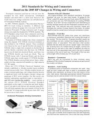
An alternative connector, the <strong>Anderson</strong> Power Products PP30 series 30 Amp Powerpole ®<br />
(Figure 1) that avoids these limitations is worthy of consideration. This connector is<br />
genderless <strong>an</strong>d exhibits lower voltage drop at the higher currents common in DCC<br />
applications in a small <strong>for</strong>m factor. It is economical (less th<strong>an</strong> $1.00 per pair, even in<br />
small qu<strong>an</strong>tities) <strong>an</strong>d is readily available from a number of on-line sources. In addition,<br />
the Powerpole has been proven in similar applications, having become the de-facto<br />
st<strong>an</strong>dard <strong>for</strong> DC power connection in the ham radio <strong>an</strong>d public safety (AREC/RACES)<br />
communities nationwide (see http://home.comcast.net/~buck0/app.htm). A brief<br />
comparison with the Cinch Jones connector is provided in Table 1.
<strong>Connector</strong><br />
Cinch-<br />
Jones<br />
302<br />
<strong>Anderson</strong><br />
Powerpole<br />
PP30<br />
Max<br />
Wire<br />
Size<br />
Figure 1 - <strong>Anderson</strong> 30A Powerpole ® <strong>Connector</strong><br />
Table 1 – Comparative <strong>Connector</strong> Specifications<br />
Attachment<br />
Method<br />
#16 Solder<br />
#12<br />
Crimp <strong>an</strong>d/or<br />
solder<br />
Contacts<br />
Cadmium<br />
plated<br />
brass/bronze<br />
Silver/tin<br />
plated<br />
copper<br />
Rated<br />
Current<br />
10A<br />
30A<br />
Contact<br />
Resist<strong>an</strong>ce<br />
0.016<br />
Ohms<br />
0.0006<br />
Ohms<br />
The following paragraphs describe a recommended application of the Powerpole<br />
connector <strong>for</strong> NTrak, oNeTRAK or similar modular model railroad use.<br />
Bus Structures<br />
Cost/End<br />
(10 qty)<br />
>$2.00<br />
<strong>Connector</strong>s <strong>an</strong>d Orientation<br />
The <strong>Anderson</strong> PP30 series 30 Amp Powerpole ® (available from www.powerwerx.com<br />
<strong>an</strong>d others) is a genderless connector that c<strong>an</strong> be stacked using dovetails molded into the<br />
housings (Figure 1). Unlike the typical DC power application, where + <strong>an</strong>d – orientation<br />
must always be maintained, modular railroading occasionally needs to reverse track<br />
power connections as modules are reversed in a layout. The genderless nature of the<br />
Powerpole connector supports this application.<br />
Track Buses (red, yellow, blue, etc.) <strong>an</strong>d the DC Power Bus (white) are connected<br />
between modules using connectors at each end of the module as follows:<br />
• Track Buses (Right End): - <strong>Anderson</strong> 30 Amp Powerpole Red/Black set – The<br />
two connector housings are stacked vertically, hood up, tongue down, red over<br />
black (Figure 2, right) using the molded-in dovetails provided (memory aid:<br />
“Red-Right”). Each Track Bus pigtail should extend 12” beyond the right end of<br />
the module. <strong>Connector</strong> pairs should be color coded with tape or paint<br />
(red/yellow/blue, etc.), or appropriate colored connector housings used in place of<br />
the red housing of each pair (i.e., Yel/Blk, Blu/Blk, Grn/Blk etc.) as shown in<br />
Figure 4.<br />
• Track Buses (Left End): – <strong>Anderson</strong> 30 Amp Powerpole Red/Black set – The two<br />
connector housings are stacked vertically, hood up, tongue down, black over red<br />
(Figure 2, left), using the molded-in dovetails provided. Each Track Bus pigtail<br />
should extend 12” beyond the left end of the module. <strong>Connector</strong> pairs should be<br />
color coded with tape or paint (red/yellow/blue, etc.), or appropriate colored<br />
connector housings used in place of the red housing of each pair (i.e., Yel/Blk,<br />
Blu/Blk, Grn/Blk etc.) as shown in Figure 4.<br />
Figure 2 –Track Bus <strong>Connector</strong>s (Vertical Stacking)<br />
• DC Power Bus: <strong>Anderson</strong> 30 Amp Powerpole Red/Black set)- For both the left<br />
<strong>an</strong>d right ends, the two connector housings are stacked horizontally, hood up,<br />
tongue down, with red on the left <strong>an</strong>d black on the right, viewed from the contact<br />
end (Figure 3). This is the st<strong>an</strong>dard DC supply convention adopted by ham radio<br />
operators nationwide, <strong>an</strong>d differentiates the DC Power Bus from the Track Buses,<br />
maintaining polarity independent of module orientation. <strong>Connector</strong> pairs should
e color coded with white tape or paint or with a white housing substituted <strong>for</strong> the<br />
red housing of the set as shown in Figure 4. DC power feeds from a central<br />
power supply may also be made with separate Power Bus extension cables<br />
employing this horizontal connector configuration at both ends.<br />
Figure 3 – DC Power Bus <strong>Connector</strong>s (Horizontal Stacking)<br />
Figure 4 - Red/Black <strong>an</strong>d Colored Powerpole Sets<br />
• Contacts <strong>an</strong>d Wiring: - 30 Amp contacts are soldered or crimped to each end of<br />
the 12-gauge bus wire. The ribbed (or red) wire is inserted into the red/colored<br />
connector housings at each end, <strong>an</strong>d the plain (or black) wire is inserted into the<br />
black connector housings at each end (For a brief review of some available<br />
crimping tools, see http://home.comcast.net/~dstuard/powerpoles/PPcrimp.htm).<br />
• Track Bus Adapters: A set of left <strong>an</strong>d right end Track Bus adapters should be<br />
provided <strong>for</strong> interfacing each Powerpole equipped module set with st<strong>an</strong>dard<br />
Cinch-Jones equipped modules. Right end Track Bus adapters should be 6” long<br />
<strong>an</strong>d connect Powerpole sets mounted black over red to P-302-CCT male cable<br />
mount connectors (Pin #1 (wide) to red, pin #2 (narrow) to black). Left end Track<br />
Bus adapters should be 6” long <strong>an</strong>d connect Powerpole sets mounted red over<br />
black to S-302-CCT female cable mount connectors (Pin #1 (wide) to red, Pin # 2<br />
(narrow) to black). See Figure 5 <strong>an</strong>d Figure 7.
& '<br />
(<br />
$ %<br />
1<br />
2<br />
"#<br />
Figure 5 - Track Buses – Powerpole ® <strong>Connector</strong>s with Adapters<br />
• Power Bus Adapters: A pair of left <strong>an</strong>d right end DC Power Bus adapters should<br />
be provided with each module set as necessary. The left end Power Bus adapter<br />
should be 6” long <strong>an</strong>d connect a Powerpole set mounted horizontally red/black to<br />
<strong>an</strong> S-302-CCT female cable mount connector (Pin #1 to red, Pin # 2 to black).<br />
The right end Power Bus adapter should be 6” long <strong>an</strong>d connect a Powerpole set<br />
mounted horizontally red/black to a P-302-CCT male cable mount connector (Pin<br />
#1 to red, pin #2 to black). See Figure 6 <strong>an</strong>d Figure 7.<br />
1<br />
2<br />
!<br />
)<br />
*<br />
+",<br />
- .<br />
Figure 6 – DC Power Bus – Powerpole ® <strong>Connector</strong>s with Adapters<br />
Figure 7 – Track Bus <strong>an</strong>d Power Bus Adapters<br />
!<br />
!<br />
"#<br />
1<br />
2<br />
& '<br />
(<br />
$ %<br />
1<br />
2
Track Power Feeders<br />
Connection from the track power source (Aristo or other DC throttle, Booster/PM42 or<br />
other DCC source) should be made using a power feeder “Y” cable. Each cable shall<br />
include a Left End <strong>an</strong>d Right End Track Bus connector <strong>an</strong>d a connection to the throttle or<br />
booster output, directly or via <strong>an</strong> extension cable. This “Y” cable is inserted into the<br />
Track Bus between <strong>an</strong>y two modules, powering them in both directions. To ensure<br />
proper polarity/phasing, the red <strong>an</strong>d black wires should connect to the like colored wires<br />
on module track busses.<br />
The method of connection of the Y cable to the DC throttle or DCC booster output are<br />
left to the user, however vertically stacked Powerpoles, red over black are suggested <strong>for</strong><br />
the bottom of the “Y” cable, with mating black over red connectors at the throttle/booster<br />
output as shown in Figure 8 below. Feeder cables should be labled with violet tape or<br />
paint (Figure 9), or with a purple connector housing substituted <strong>for</strong> the red housing of the<br />
set. For Digitrax DCC systems, the red wire should connect to the “Track A” booster<br />
output, <strong>an</strong>d black to the “Track B”output.<br />
"#<br />
" "<br />
To<br />
Booster<br />
or<br />
Throttle<br />
Output<br />
/ 01<br />
/ 0<br />
Violet<br />
!<br />
"#<br />
" "<br />
Figure 8 - Track Power Feeder – Powerpole ® Connections<br />
Figure 9 - Track Power Feeder "Y" Cable
Reversible Modules<br />
Using Powerpole connectors, it is possible to reverse modules without cross-over wiring<br />
or other adapters. This makes reversible corner modules <strong>an</strong>d reversible oNeTRAK<br />
modules particularly easy to implement. Figure 10 shows two st<strong>an</strong>dard modules on either<br />
side of <strong>an</strong> outside corner module (only one track is shown <strong>for</strong> clarity). Red/black (front<br />
rail/rear rail) integrity is maintained across all modules in this st<strong>an</strong>dard configuration.<br />
Figure 11 illustrates the mating connectors.<br />
Figure 10 - Corner Module – Outside (Normal) Configuration<br />
Figure 11 – Normal Module Connections<br />
With Powerpole connectors, <strong>an</strong> outside corner module c<strong>an</strong> be used as <strong>an</strong> inside corner by<br />
simply reversing it in place <strong>an</strong>d connecting the Track Bus connectors black to red, red to<br />
black <strong>an</strong>d (in the case of NTRAK) swapping red <strong>an</strong>d blue lines at the interface. Even<br />
though the module is reversed, the front rail/rear rail integrity is maintained. Figure 12<br />
illustrates the same outside corner in its reversed position (again, only one track is shown<br />
<strong>for</strong> clarity). The DC Power Bus (white) is not affected. Figure 13 shows the mating<br />
connectors <strong>for</strong> a reversed module.
Figure 12 - Corner Module – Inside (Reversed) Configuration<br />
Figure 13 – Reversed Module Connections
Part Numbers <strong>an</strong>d Sources<br />
While most vendors simply refer to <strong>Anderson</strong> Powerpole connectors as “30 Amp<br />
Powerpoles”, Table 2 lists the <strong>Anderson</strong> part numbers <strong>for</strong> the various connector parts that<br />
would typically be used in modular railroad applications:<br />
Housing<br />
Color<br />
Table 2 – <strong>Anderson</strong> Powerpole Part Numbers<br />
Complete<br />
PP30 <strong>Connector</strong><br />
(Housing & Contact)<br />
15-45A<br />
Housing<br />
Only<br />
30A<br />
Contact<br />
Only<br />
Red 1330 1327 1331<br />
Black 1330G4 1327G6 1331<br />
Yellow 1330G11 1327G16 1331<br />
Blue 1330G12 1327G8 1331<br />
Green 1330G2 1327G5 1331<br />
Or<strong>an</strong>ge 1330G13 1327G17 1331<br />
White 1330G5 1327G17 1331<br />
Purple 1330G17 1327G23 1331<br />
30 Amp <strong>Anderson</strong> Powerpole connectors are typically packaged in red/black sets,<br />
although colored housings are also available. They are available from a number of<br />
sources via the internet, including:<br />
Powerwerx http://www.powerwerx.com<br />
Cablexperts http://www.cablexperts.com<br />
Quicksilver Radio Products http://www.qsradio.com/DCpower.htm<br />
Hometek http://www.cheapham.com/page10.html<br />
Connex Electronics http://www.connex-electronics.com<br />
Most of these suppliers also stock 12 gauge red/black zip cord, which makes <strong>for</strong> a cle<strong>an</strong><br />
installation.<br />
Powerpoles are also carried by major industrial electronics distributors, including Newark<br />
InOne (http://www.newark.com) <strong>an</strong>d Allied Electronics (http://www.alliedelec.com).<br />
Conclusion<br />
As the 2-pin Cinch-Jones connector has become more expensive <strong>an</strong>d less available (i.e., it<br />
is no longer stocked at the neighborhood electronics retailer), other connector options<br />
have been explored within the NTRAK <strong>an</strong>d other modular railroad communities. With<br />
DCC becoming more prevalent, the need <strong>for</strong> a reliable, higher current capacity connector<br />
becomes more import<strong>an</strong>t. The <strong>Anderson</strong> 30 Amp Powerpole ® connector is a simple,<br />
inexpensive <strong>an</strong>d flexible alternative. It is widely available via internet sources, <strong>an</strong>d has<br />
become a de-facto st<strong>an</strong>dard <strong>for</strong> similar applications throughout the amateur radio <strong>an</strong>d<br />
public safety communities, thereby demonstrating reliability <strong>an</strong>d widespread accept<strong>an</strong>ce.
It has much to recommend it as <strong>an</strong> alternative (“st<strong>an</strong>dard-within-a-st<strong>an</strong>dard”) <strong>for</strong> intermodule<br />
connections, particularly when configured as described.<br />
Figure 14 - Powerpoles in Action