

The Ericsson Group 1968 - History of Ericsson - History of Ericsson
The Ericsson Group 1968 - History of Ericsson - History of Ericsson
The Ericsson Group 1968 - History of Ericsson - History of Ericsson

Create successful ePaper yourself
Turn your PDF publications into a flip-book with our unique Google optimized e-Paper software.
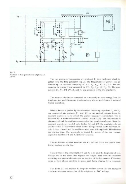
Fig. 2<br />
Insertion <strong>of</strong> tone generator in telephone set<br />
circuit<br />
52<br />
<strong>The</strong> two groups <strong>of</strong> frequencies are produced by two oscillators which together<br />
form the tone generator (fig. 2). <strong>The</strong> frequencies for group I are generated<br />
by an oscillator consisting <strong>of</strong> IC2, TL, Rrl, V\, CL, CI. <strong>The</strong> frequencies<br />
for group II are generated by IC 3, Tn, Rell, V2, Cu. C2. <strong>The</strong> components<br />
Ri, D\, D2, D3, Rz and VI are common to the two oscillators.<br />
<strong>The</strong> resonant circuits are connected so as normally to store energy from the<br />
telephone line, and this energy is released only when a push-button is actuated<br />
(shock excitation).<br />
When a button is pushed by the subscriber, the tuning capacitors C, and Cu<br />
are connected via contacts K\ and K2 to the desired outputs from the<br />
resonant circuits so as to obtain the correct frequency combination. This is<br />
followed by a make-before-break contact action (K3). <strong>The</strong> microphone is<br />
disconnected and the oscillator connected to the speech transformer. Since the<br />
resonant circuits are loaded with diodes D2 and £>3, the oscillators do not<br />
oscillate until A'3 disconnects these diodes. Energy stored in the resonant circuits<br />
is then released and the oscillators start near full amplitude. This shortens<br />
the starting time. <strong>The</strong> amplitude is limited by means <strong>of</strong> the two voltagedependent<br />
resistors V\ and V2 (silicon varistors).<br />
<strong>The</strong> oscillations are then extended via K3, D2 and D3 to the speech transformer<br />
and out on the line.<br />
<strong>The</strong> purpose <strong>of</strong> the components V3 and Rz is to limit the telephone set D.C.<br />
voltage and at the same time regulate the output level from the oscillator<br />
according to a desired characteristic as function <strong>of</strong> the line current. V3 is composed<br />
<strong>of</strong> two silicon varistors in series, each being shunted by a resistance.<br />
<strong>The</strong> diode D\ and resistor Ri keep the emitter current for the respective<br />
transistors constant irrespective <strong>of</strong> the telephone set D.C. voltage.


