RFC Kit Installation Instructions - Simkar Corporation
RFC Kit Installation Instructions - Simkar Corporation
RFC Kit Installation Instructions - Simkar Corporation

You also want an ePaper? Increase the reach of your titles
YUMPU automatically turns print PDFs into web optimized ePapers that Google loves.
D<br />
C<br />
B<br />
A<br />
8<br />
THE DATA AND INFORMATION DISCLOSED ON THIS DRAWING ARE THE EXCLUSIVE PROPERTY<br />
OF SIMKAR CORPORATION, AND MAY BE SUBJECT OF UNITED STATES AND FOREIGN PATENTS<br />
OR APPLICATIONS. REPRODUCTION, COPYING, DISCLOSURE, OR USE OF THIS DRAWING DATA<br />
AND INFORMATION, IN PART OR WHOLE WITHOUT THE WRITTEN PERMISSION OF SIMKAR<br />
CORPORATION IS PORHIBITED.<br />
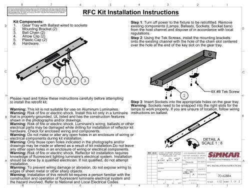
<strong>Kit</strong> Components:<br />
1. Gear Tray with Ballast wired to sockets<br />
2. Mounting Bracket (2)<br />
3. Ball Chain (2)<br />
4. Arrow Clip (2)<br />
5. Plastic Cap (2)<br />
6. Hardware<br />
1 2 4 5 3<br />
Please read and follow these instructions carefully before attempting<br />
to install the retrofit kit.<br />
<strong>RFC</strong> <strong>Kit</strong> <strong>Installation</strong> <strong>Instructions</strong><br />
Warning: This kit is not suitable for use on Aluminum Luminaires.<br />
Warning: Risk of fire or electric shock. Install this kit only in a luminaire<br />
that is properly grounded, UL listed and has the construction features<br />
shown in the photographs and/or drawings.<br />
Warning: Risk of fire or electric shock. Luminaire's wiring, ballasts or other<br />
electrical parts may be damaged while drilling for installation of reflector kit<br />
hardware. Check for enclosed wiring and components.<br />
Warning: Do not make or alter any open holes in an enclosure of wiring or<br />
electrical components during kit installation.<br />
Warning: Only those open holes indicated in the photographs and/or<br />
drawings may be made or altered as a result of kit installation.Do not leave<br />
any other open holes in an enclosure of wiring or electrical components.<br />
Warning: Risk of fire or electric shock. Reflector kit installation requires<br />
knowledge of fluorescent lighting luminaire's electrical system. <strong>Installation</strong><br />
should be done by a qualified electrician. If not qualified, do not attempt<br />
installation.<br />
Warning: To prevent wiring damage or abrasion, do not expose wiring to<br />
edges of sheet metal or other sharp objects.<br />
Warning: <strong>Installation</strong> of this retrofit kit requires a person familiar with the<br />
construction and operation of fluorescent luminaire electrical system and<br />
the hazard involved. Refer to National and Local Electrical Codes.<br />
8<br />
7<br />
7<br />
6<br />
6<br />
5<br />
5<br />
4<br />
Step 1: Turn off power to the fixture to be retrofitted. Remove<br />
existing components (Lamps, Ballasts, Sockets, Socket bars)<br />
from the host channel and dispose of in accordance with local<br />
regulations.<br />
Step 2: Using the Tek Screws, install the mounting brackets<br />
onto the existing channel with the hole of the chain slot centered<br />
over the hole at the end of the key slot on the gear tray.<br />
A<br />
2<br />
4X #8 Tek Screw<br />
Step 3: Insert Sockets into the appropriate holes on the gear tray.<br />
Warning: Sockets need to be snapped into the right slots for the<br />
lamps to work properly. If you are unsure of location, follow wiring<br />
instructions on ballast.<br />
4<br />
REV ECO<br />
UNLESS OTHERWISE SPECIFIED<br />
DIMENSIONS ARE IN INCHES<br />
TOLERANCES ARE:<br />
.XX .XXX ANGLES<br />
0.063 0.015 1<br />
MATERIAL<br />
THICKNESS<br />
FINISH<br />
PART VOLUME :<br />
3<br />
IN<br />
3<br />
PART WEIGHT:<br />
3<br />
LB<br />
CAD GENERATED DRAWING<br />
DO NOT MANUALLY UPDATE<br />
DO NOT SCALE DRAWING<br />
DRAWN<br />
APPROVED<br />
DENSITY:<br />
LB/IN 3<br />
Drawing<br />
Model<br />
DHarathi<br />
Last<br />
dharathi<br />
CNC REV :<br />
PROGRAM<br />
A<br />
2<br />
<strong>RFC</strong> <strong>Instructions</strong> for UL<br />
<strong>RFC</strong> 4FT 2L T8<br />
2<br />
DETAIL A<br />
SCALE 1 : 8<br />
03/16/2012 PART DESCRIPTION<br />
4/26/2012<br />
PART No :<br />
03/16/2012<br />
700 Ramona Ave.Philadelphia, PA 19120<br />
<strong>RFC</strong> INSTALLATION INSTRUCTIONS<br />
SCALE :<br />
1:12<br />
1<br />
70-62884<br />
SHEET<br />
1<br />
1<br />
OF<br />
2<br />
D<br />
C<br />
B<br />
A
D<br />
C<br />
B<br />
A<br />
8<br />
THE DATA AND INFORMATION DISCLOSED ON THIS DRAWING ARE THE EXCLUSIVE PROPERTY<br />
OF SIMKAR CORPORATION, AND MAY BE SUBJECT OF UNITED STATES AND FOREIGN PATENTS<br />
OR APPLICATIONS. REPRODUCTION, COPYING, DISCLOSURE, OR USE OF THIS DRAWING DATA<br />
AND INFORMATION, IN PART OR WHOLE WITHOUT THE WRITTEN PERMISSION OF SIMKAR<br />
CORPORATION IS PORHIBITED.<br />
Step 4: Feed the chains through the slots on the gear tray<br />
with the "bell end" below the pan.<br />
DETAIL B<br />
SCALE 1 : 2<br />
3<br />
Slot on Gear Tray<br />
B<br />
Step 5: Lift the gear tray assembly and insert the other end of<br />
the chain into the slot on the mounting bracket and make sure<br />
the chains are holding the assembly securely.<br />
8<br />
C<br />
7<br />
7<br />
6<br />
DETAIL C<br />
SCALE 1 : 6<br />
6<br />
5<br />
Insert chain through<br />
this opening on the<br />
mounting bracket and<br />
slide back into it.<br />
5<br />
4<br />
Step 6: With the gear tray assembly securely hanging from the chains,<br />
connect the existing ground wire on the luminaire to the ground wire<br />
provided on the gear tray using a wire nut. Warning: Gear tray must be<br />
grounded to avoid electric shock while servicing. Then, wire the ballast to<br />
supply wires by inserting the black and white wires into the disconnect.<br />
Step 7: Push the gear tray until it touches the ends on the housing. Pull<br />
the chains down and lock the gear tray into place by sliding the chain<br />
into the key hole slot.<br />
4<br />
Step 9: Install lamps and turn on power.<br />
5<br />
Pull and lock the chain<br />
as shown.<br />
Step 8: Coil up the remaining chain into the plastic cap provided. Using<br />
the arrow clip, mount the cap onto the gear tray by pushing the clip<br />
through the hole on the cap and into the center hole of the slot on the<br />
gear tray.<br />
4<br />
REV ECO<br />
UNLESS OTHERWISE SPECIFIED<br />
DIMENSIONS ARE IN INCHES<br />
TOLERANCES ARE:<br />
.XX .XXX ANGLES<br />
0.063 0.015 1<br />
MATERIAL<br />
THICKNESS<br />
FINISH<br />
PART VOLUME :<br />
3<br />
IN<br />
3<br />
PART WEIGHT:<br />
3<br />
LB<br />
CAD GENERATED DRAWING<br />
DO NOT MANUALLY UPDATE<br />
DO NOT SCALE DRAWING<br />
DRAWN<br />
APPROVED<br />
DENSITY:<br />
LB/IN 3<br />
Drawing<br />
Model<br />
DHarathi<br />
Last<br />
dharathi<br />
CNC REV :<br />
PROGRAM<br />
A<br />
2<br />
<strong>RFC</strong> <strong>Instructions</strong> for UL<br />
Chain-Gear Tray<br />
03/16/2012 PART DESCRIPTION<br />
PART No :<br />
03/16/2012<br />
2<br />
4/26/2012<br />
700 Ramona Ave.Philadelphia, PA 19120<br />
<strong>RFC</strong> INSTALLATION INSTRUCTIONS<br />
SCALE :<br />
1:12<br />
1<br />
70-62884<br />
SHEET<br />
1<br />
2<br />
OF<br />
2<br />
D<br />
C<br />
B<br />
A