XR-i IGNITION - Crane Cams
XR-i IGNITION - Crane Cams
XR-i IGNITION - Crane Cams

Create successful ePaper yourself
Turn your PDF publications into a flip-book with our unique Google optimized e-Paper software.
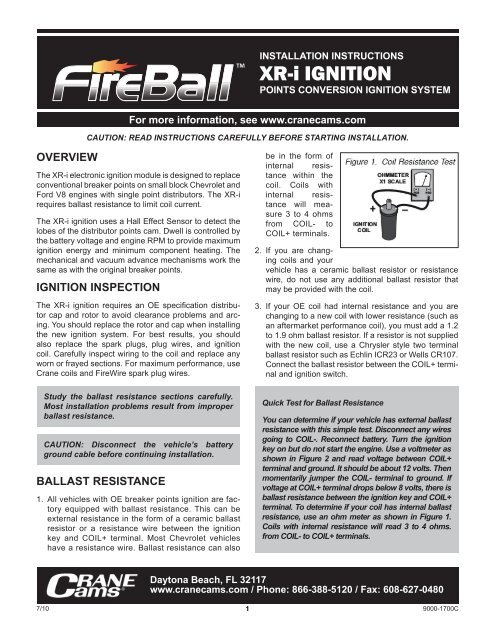
OVERVIEW<br />
INSTALLATION INSTRUCTIONS<br />
<strong>XR</strong>-i <strong>IGNITION</strong><br />
POINTS CONVERSION <strong>IGNITION</strong> SYSTEM<br />
For more information, see www.cranecams.com<br />
CAUTION: READ INSTRUCTIONS CAREFULLY BEFORE STARTING INSTALLATION.<br />
The <strong>XR</strong>-i electronic ignition module is designed to replace<br />
conventional breaker points on small block Chevrolet and<br />
Ford V8 engines with single point distributors. The <strong>XR</strong>-i<br />
requires ballast resistance to limit coil current.<br />
The <strong>XR</strong>-i ignition uses a Hall Effect Sensor to detect the<br />
lobes of the distributor points cam. Dwell is controlled by<br />
the battery voltage and engine RPM to provide maximum<br />
ignition energy and minimum component heating. The<br />
mechanical and vacuum advance mechanisms work the<br />
same as with the original breaker points.<br />
<strong>IGNITION</strong> INSPECTION<br />
The <strong>XR</strong>-i ignition requires an OE specification distributor<br />
cap and rotor to avoid clearance problems and arcing.<br />
You should replace the rotor and cap when installing<br />
the new ignition system. For best results, you should<br />
also replace the spark plugs, plug wires, and ignition<br />
coil. Carefully inspect wiring to the coil and replace any<br />
worn or frayed sections. For maximum performance, use<br />
<strong>Crane</strong> coils and FireWire spark plug wires.<br />
Study the ballast resistance sections carefully.<br />
Most installation problems result from improper<br />
ballast resistance.<br />
CAUTION: Disconnect the vehicle’s battery<br />
ground cable before continuing installation.<br />
BALLAST RESISTANCE<br />
1. All vehicles with OE breaker points ignition are factory<br />
equipped with ballast resistance. This can be<br />
external resistance in the form of a ceramic ballast<br />
resistor or a resistance wire between the ignition<br />
key and COIL+ terminal. Most Chevrolet vehicles<br />
have a resistance wire. Ballast resistance can also<br />
<br />
be in the form of<br />
internal resistance<br />
within the<br />
coil. Coils with<br />
internal resistance<br />
will measure<br />
3 to 4 ohms<br />
from COIL- to<br />
COIL+ terminals.<br />
2. If you are changing<br />
coils and your<br />
vehicle has a ceramic ballast resistor or resistance<br />
wire, do not use any additional ballast resistor that<br />
may be provided with the coil.<br />
3. If your OE coil had internal resistance and you are<br />
changing to a new coil with lower resistance (such as<br />
an aftermarket performance coil), you must add a 1.2<br />
to 1.9 ohm ballast resistor. If a resistor is not supplied<br />
with the new coil, use a Chrysler style two terminal<br />
ballast resistor such as Echlin ICR23 or Wells CR107.<br />
Connect the ballast resistor between the COIL+ terminal<br />
and ignition switch.<br />
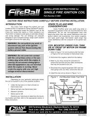
Quick Test for Ballast Resistance<br />
You can determine if your vehicle has external ballast<br />
resistance with this simple test. Disconnect any wires<br />
going to COIL-. Reconnect battery. Turn the ignition<br />
key on but do not start the engine. Use a voltmeter as<br />
shown in Figure 2 and read voltage between COIL+<br />
terminal and ground. It should be about 12 volts. Then<br />
momentarily jumper the COIL- terminal to ground. If<br />
voltage at COIL+ terminal drops below 8 volts, there is<br />
ballast resistance between the ignition key and COIL+<br />
terminal. To determine if your coil has internal ballast<br />
resistance, use an ohm meter as shown in Figure 1.<br />
Coils with internal resistance will read 3 to 4 ohms.<br />
from COIL- to COIL+ terminals.<br />
Daytona Beach, FL 32117<br />
www.cranecams.com / Phone: 866-388-5120 / Fax: 608-627-0480<br />
7/10 1<br />
9000-1700C
GM 8 CYLINDER DISTRIBUTOR<br />
1. Refer to Figure 3. Use the supplied hardware. Check the<br />
orientation of the adapter bracket, it will only fit one way.<br />
2. Apply thermal grease to the bottom side of the <strong>XR</strong>-i<br />
module. Install the 6-32 hardware by hand to secure<br />
the module to the adapter plate. The module will be<br />
positioned to adjust the air gap later.<br />
3. Apply thermal grease to the bottom of the adapter<br />
plate. Install the module and adapter plate in the<br />
location that the breaker points were removed from.<br />
Firmly tighten the 8-32 supplied hardware to secure<br />
the adapter plate to the distributor.<br />
4. Route the wires as shown in Figure 4. Be sure that<br />
the wires do not interfere with the vacuum advance<br />
mechanism.<br />
5. Install the supplied grommet over the wire harness<br />
and insert into the cable exit of the distributor. A lubricant<br />
such as WD40 is helpful in installing the grommet.<br />
Install the cable clamp as shown in Figure 4<br />
using the supplied 8- 32 screw.<br />
6. Loosen the 6-32 hardware to allow the <strong>XR</strong>-i module to<br />
slide on the adapter plate. Push the module as close<br />
to the points cam as possible without touching the<br />
points cam lobe. Tighten the hardware to secure the<br />
module in place.<br />
FORD 8 CYLINDER DISTRIBUTOR<br />
Remove distributor from vehicle. Ford distributors require<br />
removal of original points plate assembly. Refer to Figure<br />
5 to perform the following steps:<br />
1. Remove the e-clip holding the vacuum linkage arm to<br />
the points plate with a small screwdriver.<br />
2. Remove the 2 screws and the vacuum mechanism<br />
from the distributor body and set aside.<br />
3. Carefully remove the 2 screws holding the points plate<br />
assembly to the inside of the distributor. Use WD40 or<br />
similar solvent to lubricate these screw to avoid damage<br />
to the threads in the distributor body.<br />
4. Remove the points plate assembly from the distributor.<br />
This assembly should be saved since replacements<br />
are not available.<br />
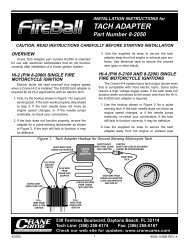
Refer to Figure 6 to perform the following steps for installation<br />
of the adapter plates and the <strong>XR</strong>-i ignition:<br />
1. Press the nylon center ring into the bottom plate and<br />
ensure it is fully seated.<br />
2. Test fit the top adapter plate on the center ring. If it<br />
does not rotate smoothly,<br />
polish the inner diameter<br />
of the top adapter plate<br />
with fine emery cloth until<br />
it does rotate smoothly.<br />
3. Press the four supplied<br />
nylon slides into the top<br />
plate from the bottom<br />
side.<br />
4. Assemble the adapter<br />
plates and the center<br />
ring. Align the two small cut outs in the top plate with<br />
the mounting holes in the bottom plate. If they do not<br />
align, flip the bottom plate over.<br />
5. Place the adapter plate assembly into the distributor<br />
and align the holes in the bottom plate with the holes<br />
in the distributor body.<br />
6. Place the larger ring terminal of the jumper wire on one<br />
of the supplied 8-32 screws with the flat side of the ring<br />
terminal facing away from the head of the screw.<br />
7/10 2<br />
9000-1700C
7. Secure the adapter plate assembly to distributor with the<br />
8-32 screws, plastic washers, and aluminum spacers as<br />
shown. It is recommended to apply a thread lock compound<br />
such as Locktite to the screw before installing<br />
them in the distributor.<br />
8. Route the <strong>XR</strong>-i wire harness through the hole in the distributor<br />
as shown.<br />
9. Install the supplied grommet over the wire harness and<br />
insert into the cable exit of the distributor. A lubricant<br />
such as WD40 is helpful in installing the grommet.<br />
10.Apply thermal grease to the bottom side of the <strong>XR</strong>-i<br />
module. Install the 6-32 hardware but do not tighten.<br />
The jumper wire must be installed on the <strong>XR</strong>-i mounting<br />
ear with the metal pad. The flat side of the ring terminal<br />
should contact the <strong>XR</strong>-i mounting ear.<br />
11.Push the module as close to the points cam as possible<br />
without touching the points cam lobe. Tighten the hardware<br />
to secure the module in place.<br />
COMPLETING THE INSTALLATION<br />
1. Refer to Figure 7. Connect the black/yellow wire of the<br />
module to the Coil- terminal of the coil with one of the<br />
ring terminals, and connect the other ring terminal to<br />
the black/red wire of the module and connect this to the<br />
COIL + terminal of the COIL.<br />
2. Double check all connections. Reconnect the battery if<br />
you have not already done so. Momentarily crank engine<br />
and visually check for clearance around all parts.<br />
3. Start your engine and set ignition timing according to<br />
manufacturer’s specifications. Note: Dwell meter readings<br />
are meaningless with electronic ignitions and should<br />
be ignored.<br />
TROUBLESHOOTING<br />
TACH INOPERATIVE<br />
1. Most tachs are connected to the COIL- terminal. If the<br />
tach is inoperative, trace out the wire. Refer to the vehicle<br />
service manual for further information.<br />
2. If the tach is erratic or reads high, you can put a resistor in<br />
the tach wire to reduce the signal level. Start with a 10K<br />
ohm 1/2 watt. You can go as low as 1K ohm 1/2 watt. You<br />
can buy the resistors from Radio Shack or other electronic<br />
suppliers. Solder into tach wire and wrap with electrical<br />
tape for protection. If the resistor fix does not help, you may<br />
require a tach adapter. Refer to Figure 8.<br />
ENGINE WILL NOT START<br />
1. Pull the high voltage coil wire out of the distributor and connect<br />
it to a test spark plug or place the wire 3/8” away from<br />
ground. Crank the engine. If sparks fire, the problem is in<br />
the secondary system. Possible causes: rotor left out, rotor,<br />
cap, or spark plug wires defective, or timing is off (distributor<br />
was moved, or plug wire firing order was changed).<br />
2. If there are no sparks, connect a test light between COIL-<br />
(negative) terminal and ground. Crank the engine. If the<br />
light flashes on and off, the module is okay, but the coil<br />
may have failed. Try another coil.<br />
7/10 3<br />
9000-1700C
3. If the light does not flash, repeat test<br />
in step 2 with a known good coil. Try<br />
disconnecting any wires to COILother<br />
than the black/ yellow wire from<br />
the <strong>Crane</strong> module. The only extra<br />
wire normally connected to COIL- is<br />
the tach wire. If the light still does not<br />
flash, the module may have failed.<br />
4. Fuel injected vehicles only. The fuel<br />
injection system typically requires a<br />
trigger signal from the COIL- terminal.<br />
Refer to vehicle service manual<br />
for details.<br />
CHECK ELECTRICAL<br />
CONNECTIONS<br />
1. Check ground connection. Verify continuity<br />
from the tin plated tab of the<br />
module to chassis ground. If there is no<br />
continuity, remove the 6-32 screw and<br />
lockwasher, clean with isopropyl alcohol,<br />
and reinstall.<br />
2. Check voltage at COIL+ (positive) terminal<br />
while cranking engine. Reading<br />
should be at least 9 volts. If less than 9 volts, check battery<br />
and starter system. If the reading is close to zero, check<br />
wiring back to ignition switch and battery. Some applications<br />
use a starter bypass to bypass the ballast resistor<br />
while cranking. This wire comes from the starter solenoid,<br />
relay, or ignition switch. Check your wiring diagram.<br />
ROUGH OR INTERMITTENT OPERATION<br />
1. Check for disconnected or cracked vacuum hoses,<br />
stuck PCV valve, or clogged fuel filter. These problems<br />
may cause symptoms similar to ignition trouble.<br />
2. Check electrical connections and optical trigger as<br />
explained in the above sections. Check for loose or<br />
corroded connections and broken wires. Try a different<br />
ground connection point on the engine block or chassis.<br />
Check distributor for loose or misaligned parts in optical<br />
trigger assembly or advance mechanism.<br />
3. Replace spark plugs. Check for proper heat range and<br />
gap size. Replace rotor, cap, spark plug wires, and coil.<br />
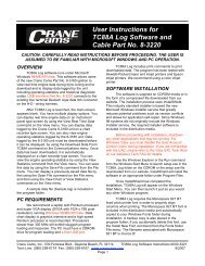
REV LIMIT SETTING<br />
The rev limit of the <strong>XR</strong>-i ignition is intended to be used as<br />
a safety feature to prevent engine damage in overrevving<br />
situations such as missed shifts. The potentiometer rotates<br />
270 degrees with full counter clockwise position representing<br />
4000 RPM and full clockwise representing 8000 RPM.<br />
Refer to Figure 9 below for a detailed view of the rev limit<br />
adjuster. The rev limit in Figure 9 is set to 6000 RPM.<br />
7/10 4<br />
9000-1700C