Compressor Handbook - Embraco
Compressor Handbook - Embraco
Compressor Handbook - Embraco

Create successful ePaper yourself
Turn your PDF publications into a flip-book with our unique Google optimized e-Paper software.
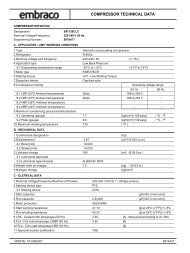
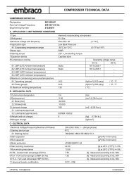
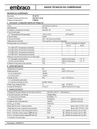
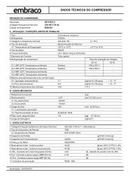
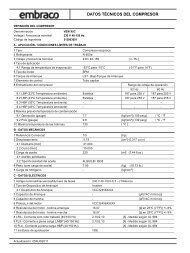
Doc. Code Emission Revision Date Page<br />
MP01EH 2000-04 07 20-02 1 - 98<br />
COMPRESSORS<br />
HANDBOOK<br />
GENERAL INDEX<br />
This handbook on hermetic compressors is designed for those working in the refrigeration field,<br />
whom already know the basic techniques of domestic and commercial refrigeration, and air conditioning.<br />
It is intended to be a guide in the selection of <strong>Embraco</strong> Europe compressors and their<br />
correct application.<br />
GENERAL INDEX<br />
1 TECHNICAL DOCUMENTS 11<br />
1.1 GENERAL CATALOG 11<br />
1.2 GENERAL GUIDE OF COMPRESSORS 11<br />
1.3 TECHNICAL BULLETIN 11<br />
1.4 ELECTRICAL COMPONENT CATALOG 12<br />
1.5 COMPRESSOR HANDBOOK 12<br />
1.6 ELECTRONIC CATALOG 12<br />
2 GENERAL INFORMATION 13<br />
2.1 COMPRESSOR RANGES 13<br />
Table 1 <strong>Compressor</strong> Series - Application - Refrigerants .................................................................................13<br />
2.2 APPLICATIONS 13<br />
Table 2 Applications...............................................................................................................................................13<br />
2.3 STARTING TORQUE CLASSIFICATION 14<br />
Table 3 Electrical motor starting torque classification....................................................................................14<br />
2.4 ELECTRIC MOTOR TYPES 14<br />
Table 4 Electrical motor types..............................................................................................................................14<br />
2.5 VOLTAGES & FREQUENCIES 15<br />
Table 5 Voltages & Frequencies ..........................................................................................................................15<br />
2.6 COMPRESSOR ELECTRICAL COMPONENTS 16<br />
Table 6 Electrical components..............................................................................................................................16<br />
2.7 COMPRESSOR COOLING TYPES 16<br />
Table 7 Cooling Types............................................................................................................................................16<br />
2.8 COMPRESSOR NAMEPLATES - IDENTIFICATION DATA 17<br />
Figure 1 Metallic Nameplates (used up to 2001) ...............................................................................................17<br />
Figure 2 Adhesive Nameplates ..............................................................................................................................17<br />
Figure 3 Series NB/NE - Adhesive Nameplates (used up to 2003) .................................................................18<br />
Figure 4 Series BP - Adhesive Nameplates (used up to 2004) .........................................................................18<br />
Figure 5 Series EM - Adhesive Nameplates ........................................................................................................18
Doc. Code Emission Revision Date Page<br />
2 - 98<br />
COMPRESSORS<br />
HANDBOOK<br />
GENERAL INDEX<br />
Figure 6a <strong>Compressor</strong> Model Identification Code .............................................................................................. 19<br />
Figure 6b Series EM - <strong>Compressor</strong> Model Identification Code ........................................................................ 20<br />
Figure 7 <strong>Compressor</strong> Bill of Materials Code ..................................................................................................... 21<br />
Figure 8 Manufacturing Date Code ..................................................................................................................... 21<br />
2.9 WIRING DIAGRAMS 22<br />
Table 8 Wiring Diagram ....................................................................................................................................... 23<br />
2.9.1 <strong>Compressor</strong> Wiring Diagram - EM Series - RSIR ............................................................................ 24<br />
Figure 9 RSIR Version terminal board with PTC starting device .................................................................. 24<br />
2.9.2 <strong>Compressor</strong> Wiring Diagram BP-NB Series – RSIR-RSCR .......................................................... 24<br />
Figure 10 RSIR and RSCR Standard Version ....................................................................................................... 24<br />
2.9.3 <strong>Compressor</strong> Wiring Diagram BP-T-NB-NE Series (electrical components without<br />
terminal board) – RSIR-CSIR .............................................................................................................. 25<br />
Figure 11 RSIR and CSIR standard version ......................................................................................................... 25<br />
2.9.4 <strong>Compressor</strong> Wiring Diagram T Series (electrical component with<br />
terminal board) – RSIR-CSIR .............................................................................................................. 25<br />
Figure 12 RSIR - CSIR terminal board version ................................................................................................... 25<br />
2.9.5 <strong>Compressor</strong> Wiring Diagram NB-NE Series (electrical component with<br />
terminal board) – RSIR-CSIR .............................................................................................................. 26<br />
Figure 13 RSIR and CSIR terminal board version .............................................................................................. 26<br />
2.9.6 <strong>Compressor</strong> Wiring Diagram NB Series (electrical component with<br />
terminal board) – RSIR-RSCR ............................................................................................................. 26<br />
Figure 14 RSIR and RSCR terminal board version with PTC starting device ............................................... 26<br />
2.9.7 <strong>Compressor</strong> Wiring Diagram T-J Series – PSC-CSR ...................................................................... 27<br />
Figure 15 PSC and CSR Versions .......................................................................................................................... 27<br />
2.9.8 <strong>Compressor</strong> Wiring Diagram NE-T-J Series – CSR BOX .............................................................. 27<br />
Figure 16 CSR BOX with internal or external overload protector ................................................................... 27<br />
2.9.9 <strong>Compressor</strong> Wiring Diagram T-J Series – CSIR .............................................................................. 28<br />
Figure 17 Standard CSIR (with the relay T.I. 3CR or G.E. 3ARR2) ................................................................ 28<br />
2.9.10 <strong>Compressor</strong> Wiring Diagram T-J Series – CSIR BOX .................................................................... 28<br />
Figure 18 CSIR BOX (with relay T.I. 3CR or G.E. 3ARR2) .............................................................................. 28<br />
2.9.11 <strong>Compressor</strong> Wiring Diagram J Series – CSIR BOX ........................................................................ 29<br />
Figure 19 CSIR BOX (with relay G.E. 3ARR3 or AMF RVA) ........................................................................... 29<br />
2.9.12 THREE PHASE ...................................................................................................................................... 29<br />
Figure 20 Three Phase ............................................................................................................................................. 29<br />
3 COMPRESSOR SUPPLY CONDITIONS 30<br />
3.1 ELECTRICAL INSULATION 30<br />
3.2 “IP” DEGREE OF PROTECTION 30<br />
Table 9 IP Degree .................................................................................................................................................. 30<br />
3.3 THE COMPRESSOR SHELL HYDROSTATIC STRENGTH 30<br />
3.4 DEHYDRATION 31<br />
Table 10 Maximum level of residual humidity .................................................................................................... 31<br />
3.5 PAINTING 31<br />
MP01EH 2000-04 07 20-02
Doc. Code Emission Revision Date Page<br />
3 - 98<br />
COMPRESSORS<br />
HANDBOOK<br />
GENERAL INDEX<br />
3.6 COMPRESSOR PRESSURISATION 31<br />
3.7 OIL CHARGE 31<br />
Table 11 Lubricant oils used in the compressors ................................................................................................32<br />
3.8 MINIMUM QUANTITY OF LUBRICANT 32<br />
Table 12 Minimum quantity of oil ..........................................................................................................................32<br />
3.9 SPECIAL VERSIONS 33<br />
Table 13 Special Version Examples .......................................................................................................................33<br />
4 COMPRESSOR PACKAGING 34<br />
4.1 MULTIPLE CARTON DISPOSABLE PACKAGE 34<br />
Table 14 Characteristics of carton multiple packages .......................................................................................34<br />
Figure 21 One Box + Shipping Skid .......................................................................................................................34<br />
Figure 22 Two Boxes + Shipping Skid ...................................................................................................................34<br />
4.1.1 <strong>Compressor</strong> Identification Marks .........................................................................................................35<br />
Figure 23 Package Label ..........................................................................................................................................35<br />
4.2 RETURNABLE WOOD PACKAGE 36<br />
Table 15 Characteristics of returnable multiple wood packages .....................................................................36<br />
Figure 25 “EM” (120 compressors) ........................................................................................................................36<br />
Figure 26 “EM” (100 compressors) ........................................................................................................................37<br />
Figure 27 “NB” (80 compressors) ..........................................................................................................................37<br />
4.2.1 <strong>Compressor</strong> identification marks ..........................................................................................................37<br />
4.3 PACKAGE FOR ELECTRICAL COMPONENTS AND ACCESSORIES 38<br />
Figure 28 Components packing label .....................................................................................................................38<br />
4.4 SINGLE PACKAGE 39<br />
Figure 29 Single <strong>Compressor</strong> Package ..................................................................................................................39<br />
5 HANDLING, TRANSPORTING AND STORING<br />
COMPRESSORS 40<br />
5.1 HANDLING 40<br />
5.2 TRANSPORTING 40<br />
5.2.1 Shipment by container ............................................................................................................................40<br />
Table 16 Load Characteristics for 20' container.................................................................................................41<br />
5.2.2 Shipments by truck ..................................................................................................................................41<br />
Table 17 Characteristics of load by truck.............................................................................................................41<br />
5.3 ACCEPTABLE COMPRESSOR POSITIONS DURING TRANSPORTATION 42<br />
Table 18 Acceptable compressor position during transportation.....................................................................42<br />
5.4 STORAGE 43<br />
Table 19 Maximum height for multiple throwaway carton packages ..............................................................43<br />
Table 20 Maximum height for multiple returnable packages............................................................................44<br />
MP01EH 2000-04 07 20-02
Doc. Code Emission Revision Date Page<br />
<br />
COMPRESSORS<br />
HANDBOOK<br />
GENERAL INDEX<br />
INFORMATION ABOUT CORRECT COMPRESSOR<br />
INSTALLATION 45<br />
45<br />
<br />
..................................................................................................... 45<br />
<br />
............................................................................................................................ 45<br />
<br />
....................................................................................................................................... 45<br />
<br />
.............................................................................................................................. 45<br />
<br />
................................................................................................... 46<br />
<br />
............................................................................................................... 46<br />
<br />
....................................................................................................................... 46<br />
............................................................................................................................................... 46<br />
<br />
......................................................................................................................... 46<br />
46<br />
47<br />
48<br />
<br />
................................................................................................................... 49<br />
Table 21 R134a Physical Characteristics ............................................................................................................ 49<br />
Table 22 R134a Ecological Characteristics ........................................................................................................ 49<br />
<br />
................................................................................................................... 52<br />
Table 23 R600a Physical characteristics ............................................................................................................. 52<br />
Table 24 R600a Ecological Characteristics....................................................................................................... 52<br />
<br />
.................................................................................................................. 54<br />
Table 25 R 404A Physical Characteristics .......................................................................................................... 54<br />
Table 26 R404A Ecological Characteristics....................................................................................................... 54<br />
<br />
.................................................................................................................. 57<br />
Table 27 R407C Physical Characteristics.......................................................................................................... 57<br />
Table 28 R407C Ecological Characteristics...................................................................................................... 57<br />
<br />
..................................................................................................................... 60<br />
Table 29 R290 Physical Characteristics .............................................................................................................. 60<br />
Table 30 R290 Ecological Characteristics .......................................................................................................... 60<br />
62<br />
Table 31 Suggested Filter Dryer............................................................................................................................ 62<br />
Table 32 Inconvenient caused by moisture in the system .................................................................................. 62<br />
63<br />
Table 33 Choice of Capillary ................................................................................................................................. 63<br />
70<br />
Figure 30 Rubber Grommets Assembling Process .............................................................................................. 70<br />
Table 34 Rubber Grommets.................................................................................................................................... 71<br />
Figure 31 Rubber Grommets ................................................................................................................................... 71<br />
73<br />
73
Doc. Code Emission Revision Date Page<br />
<br />
COMPRESSORS<br />
HANDBOOK<br />
GENERAL INDEX<br />
Table 35 Suggested tightening torques..................................................................................................................74<br />
Figure 32 Rotalock Valve .........................................................................................................................................74<br />
Figure 33 Valve Position ..........................................................................................................................................75<br />
75<br />
Table 36 Fan Coolers Characteristics...................................................................................................................75<br />
76<br />
76<br />
Table 37 Maximum Refrigerant Charge................................................................................................................76<br />
77<br />
77<br />
RUNNING DATA AND COMPRESSOR CHECKING<br />
PROCEDURES 78<br />
78<br />
<br />
................................................................78<br />
<br />
..................................................................................................79<br />
<br />
......................................................................................................79<br />
<br />
Table 38 Discharge gas maximum pressures .......................................................................................................79<br />
<br />
..........................................................................................................................79<br />
<br />
..................................................................................................................80<br />
<br />
........................................................................................................................................82<br />
<br />
Table 39 Pressure limit value..................................................................................................................................82<br />
<br />
..........................................................................................................................82<br />
<br />
............................................................................................................................................83<br />
......................................................................................................................................................83<br />
83<br />
83<br />
Table 40 Troubleshooting and service chart ........................................................................................................84<br />
87<br />
<br />
...........................................87<br />
<br />
............................................88<br />
<br />
<br />
<br />
..........................88<br />
<br />
<br />
<br />
..........................89<br />
<br />
<br />
..............90<br />
<br />
<br />
..............90<br />
<br />
<br />
...........................91<br />
<br />
..............................................................................................92<br />
<br />
<br />
....................92<br />
<br />
<br />
....93<br />
<br />
<br />
..............................................94<br />
<br />
............................................................................................................................94
Doc. Code Emission Revision Date Page<br />
<br />
COMPRESSORS<br />
HANDBOOK<br />
GENERAL INDEX<br />
95<br />
<br />
........................................................................................... 95<br />
<br />
...................................................................................... 95<br />
<br />
<br />
....................................................................................................... 95<br />
HOW TO RETURN SUPPLIED PRODUCTS<br />
TO EMBRACO EUROPE 96<br />
96<br />
97
INDEX OF FIGURES<br />
Doc. Code Emission Revision Date Page<br />
MP01E 2000-04 0 20-02 7 - 98<br />
COMPRESSORS<br />
HANDBOOK<br />
Figure 1 cilate N M a m 2 ot setalpe u desu( 0 p 0 )1<br />
71<br />
Figure 2 N evisehdA a setalpem<br />
71<br />
Figure 3 N seireS N/B A - E d eviseh N a m 2 ot setalpe u desu( 0 p 0 )3<br />
81<br />
Figure 4 B seireS A - P evisehd N a m ot setalpe u desu( 02 p )40<br />
81<br />
Figure 5 E N seireS evisehdA - a M setalpem<br />
81<br />
Figure 6a noitacifitnedI edoC M oC ledo roserpm<br />
91<br />
Figure 6b edoC noitacifitnedI ledoM rosserpmoC 02 -<br />
Figure 7 slaireta edoC M fo lliB oC roserpm<br />
12<br />
Figure 8 etaD edoC gnirutcafuna M<br />
12<br />
Figure 9 ecived gnitrats htiw TP C draob lanimret noisreV RISR<br />
42<br />
Figure 10 noisreV dradnatS dna RCSR RISR<br />
42<br />
Figure 11 noisrev dradnats RISC dna RISR<br />
52<br />
Figure 12 noisrev draob lanimret RISC - RISR<br />
52<br />
Figure 13 noisrev draob lanimret RISC dna RISR<br />
62<br />
Figure 14 ecived gnitrats htiw TP C noisrev draob lanimret dna RISR CSR R 62<br />
Figure 15 SP C<br />
dna S snoisreV R<br />
72<br />
Figure 16 rotcetorp daolrevo lanretxe C ro S lanretni R B O htiw X<br />
72<br />
Figure 17 atS 3 .I.T C dradn C yaler eht R 3 ro htiw( RIS .E.G A R R )2<br />
82<br />
Figure 18 C RIS B 3 .I.T O C htiw( yaler X R 3 ro .E.G A R R )2<br />
82<br />
Figure 19 C RIS B O 3 yaler htiw( X .E.G A R R A 3 ro M F R V )A<br />
92<br />
Figure 20 Three Phase 29<br />
Figure 21 Carton Package Unit<br />
43<br />
Figure 22 Wood Package Unit<br />
43<br />
Figure 23 Package Label 35<br />
Figure 25 “EM” (120 oc m )sroserp<br />
63<br />
Figure 26 “EM” (100 oc m )sroserp<br />
73<br />
Figure 27 “ N B ” 08( oc m )sroserp<br />
73<br />
Figure 28 C<br />
o m p o n e stn p a nikc al g b le<br />
83
Doc. Code Emission Revision Date Page<br />
<br />
COMPRESSORS<br />
HANDBOOK<br />
Figure 29 Single <strong>Compressor</strong> Package 39<br />
Figure 30 Rubber Grommets Assembling Process 70<br />
Figure 31 Rubber Grommets 71<br />
Figure 32 Rotalock Valve 74<br />
Figure 33 Valve Position 75
INDEX OF TABLES<br />
Doc. Code Emission Revision Date Page<br />
<br />
COMPRESSORS<br />
HANDBOOK<br />
Table 1 <strong>Compressor</strong> Series - Application - Refrigerants 13<br />
Table 2 Applications 13<br />
Table 3 Electrical motor starting torque classification 14<br />
Table 4 Electrical motor types 14<br />
Table 5 Voltages & Frequencies 15<br />
Table 6 Electrical components 16<br />
Table 7 Cooling Types 16<br />
Table 8 Wiring Diagram 23<br />
Table 9 IP Degree 30<br />
Table 10 Maximum level of residual humidity 31<br />
Table 11 Lubricant oils used in the compressors 32<br />
Table 12 Minimum quantity of oil 32<br />
Table 13 Special Version Examples 33<br />
Table 14 Characteristics of carton multiple packages 34<br />
Table 15 Characteristics of returnable multiple wood packages 36<br />
Table 16 Load Characteristics for 20' container 41<br />
Table 17 Characteristics of load by truck 41<br />
Table 18 Acceptable compressor position during transportation 42<br />
Table 19 Maximum height for multiple throwaway carton packages 43<br />
Table 20 Maximum height for multiple returnable packages 44<br />
Table 21 R134a Physical Characteristics 49<br />
Table 22 R134a Ecological Characteristics 49<br />
Table 23 R600a Physical characteristics 52<br />
Table 24 R600a Ecological Characteristics 52<br />
Table 25 R 404A Physical Characteristics 54<br />
Table 26 R404A Ecological Characteristics 54<br />
Table 27 R407C Physical Characteristics 57<br />
Table 28 R407C Ecological Characteristics 57<br />
Table 29 R290 Physical Characteristics 60
Doc. Code Emission Revision Date Page<br />
<br />
COMPRESSORS<br />
HANDBOOK<br />
Table 30 R290 Ecological Characteristics 60<br />
Table 31 Suggested Filter Dryer 62<br />
Table 32 Inconvenient caused by moisture in the system 62<br />
Table 33 Choice of Capillary 63<br />
Table 34 Rubber Grommets 71<br />
Table 35 Suggested tightening torques 74<br />
Table 36 Fan Coolers Characteristics 75<br />
Table 37 Maximum Refrigerant Charge 76<br />
Table 38 Discharge gas maximum pressures 79<br />
Table 39 Pressure limit value 82<br />
Table 40 Troubleshooting and service chart 84
1 TECHNICAL DOCUMENTS<br />
Doc. Code Emission Revision Date Page<br />
COMPRESSORS<br />
HANDBOOK<br />
Chapter<br />
TECHNICAL DOCUMENTS<br />
<br />
<br />
<br />
1.1 GENERAL CATALOG<br />
<br />
<br />
<br />
<br />
<br />
<br />
<br />
<br />
<br />
<br />
<br />
<br />
<br />
<br />
<br />
<br />
<br />
<br />
<br />
<br />
<br />
<br />
<br />
1.2 GENERAL GUIDE OF COMPRESSORS<br />
<br />
<br />
<br />
<br />
<br />
<br />
<br />
<br />
<br />
<br />
<br />
<br />
<br />
<br />
1.3 TECHNICAL BULLETIN
Wiring diagrams<br />
Doc. Code Emission Revision Date Page<br />
MP01E 2000-04 0 20-02 12 - 98<br />
COMPRESSORS<br />
HANDBOOK<br />
Chapter<br />
TECHNICAL DOCUMENTS<br />
Graphs of “Mass Flow”, “Current Input”, “Watt Input”, “Refrigeration Capacity”, as a function<br />
of the evaporating temperature (within the characteristic field) at two or more condensing<br />
temperatures.<br />
1.4 ELECTRICAL COMPONENT CATALOG<br />
This catalog allows the identification of the electrical components to be supplied with the <strong>Compressor</strong><br />
Model and its Bill of Lading.<br />
The information contained in the catalog is:<br />
Reference of <strong>Compressor</strong> Model & Bill of Lading.<br />
<strong>Compressor</strong> electrical data (Voltage & frequency, motor type, nominal Watt, nominal FLA,<br />
LRA, and resistance of the electrical motor).<br />
Starting relay & O/L protector characteristics and code numbers used by Aspera and suppliers.<br />
Run & start capacitors (if applicable) characteristics and Aspera code number.<br />
“Terminal board assembly” or “Electrical<br />
box” Aspera code number.<br />
The use of electrical components different that those approved by <strong>Embraco</strong> can cause<br />
abnormal working and even severe damage to compressor.<br />
1.5 COMPRESSOR HANDBOOK<br />
The <strong>Handbook</strong> includes useful information about compressors and their components and addresses<br />
the correct application of the compressors with various refrigerants.<br />
1.6 ELECTRONIC CATALOG<br />
The Electronic Catalog is available on our web site “www.embraco.com”.
2 GENERAL INFORMATION<br />
2.1 COMPRESSOR RANGES<br />
Doc. Code Emission Revision Date Page<br />
MP01E 2000-04 0 20-02 13 - 98<br />
COMPRESSORS<br />
HANDBOOK<br />
Chapter<br />
GENERAL INFORMATION<br />
Table 1 indicates the refrigerant types used in the compressors available on catalog for each series<br />
and according to the different applications.<br />
Table 1 <strong>Compressor</strong> Series - Application - Refrigerants<br />
SERIES<br />
APPLICATION<br />
LBP MBP HBP AC<br />
EM<br />
–<br />
R134a - R600a - R404A - R290 R404A - R290 R134a - R600a –<br />
NB<br />
R134a - R600a - R404A -<br />
R507<br />
R404A - R507 R22 - R134a –<br />
NE<br />
R22 - R134a - R404A - R507 -<br />
R290<br />
R404A - R507<br />
R290<br />
R22 - R134a -<br />
R600a<br />
R22 - R407C<br />
T - NT<br />
R22 - R134a - R404A - R507 - R404A - R507<br />
R290<br />
R290<br />
R22 - R134a -<br />
R22 - R407C<br />
NJ R22 - R134a - R404A - R507 R404A - R507 R22 - R134a R22 - R407C<br />
The available models in the different applications, the thermodynamic and electrical performances,<br />
the external dimensions and the approved electrical components, are listed in the General Catalog,<br />
Technical Bulletin, Electrical Components Catalog and Electronic Catalog, which<br />
complement this <strong>Handbook</strong>.<br />
2.2 APPLICATIONS<br />
Table 2 Applications<br />
TYPE DESCRIPTION<br />
(Low Back Pressure)<br />
Models at low evaporating temperatures, suitable for applications with working<br />
LBP<br />
evaporating temperatures lower than -20 °C; for instance refrigerators, freezers,<br />
frozen food cabinets, frozen food display cases, display windows, etc.<br />
(Medium Back Pressure)<br />
Models for medium evaporating temperatures, suitable for applications with work-<br />
MBP<br />
ing evaporating temperatures higher than -20 °C; such as fresh food cabinets, drink<br />
coolers, ice makers etc.<br />
(High Back Pressure)<br />
Models at high evaporating temperatures, suitable for applications with working<br />
HBP<br />
evaporating temperatures higher than -15 °C; such as fresh food cabinets, drink<br />
coolers, ice makers, dehumidifiers etc.<br />
(Air Conditioning)<br />
Models for air conditioning with R22, suitable for applications with positive work-<br />
AC<br />
ing evaporating temperatures, such as air conditioners, heat pumps and dehumidifiers.
2.3 STARTING TORQUE CLASSIFICATION<br />
Doc. Code Emission Revision Date Page<br />
COMPRESSORS<br />
HANDBOOK<br />
Chapter<br />
GENERAL INFORMATION<br />
<br />
<br />
<br />
Table 3 Electrical motor starting torque classification<br />
TYPE DESCRIPTION<br />
LS T<br />
<br />
LST<br />
<br />
<br />
H S T<br />
<br />
HST<br />
<br />
<br />
2.4 ELECTRIC MOTOR TYPES<br />
<br />
Table 4 Electrical motor types<br />
TYPE DESCRIPTION<br />
R S I R<br />
<br />
LST <br />
<br />
<br />
<br />
RSIR<br />
<br />
<br />
<br />
<br />
<br />
<br />
PTC<br />
C S I R<br />
CSIR <br />
<br />
<br />
R S C R<br />
RSCR <br />
<br />
<br />
<br />
P S C<br />
<br />
<br />
<br />
PSC
2.5 VOLTAGES & FREQUENCIES<br />
ASPERA<br />
CODE<br />
Doc. Code Emission Revision Date Page<br />
MP01E 2000-04 0 20-02 15 - 98<br />
COMPRESSORS<br />
HANDBOOK<br />
Chapter<br />
GENERAL INFORMATION<br />
TYPE DESCRIPTION<br />
Capacitive Start & Run<br />
CSR version with capacitive run and start windings. Same as PSC motor but with a<br />
CSR start capacitor in series with the start winding. A potential starting relay, calibrated<br />
for each motor, disconnects the start capacitor at the end of the start. The motor is<br />
characterized by a high starting torque (HST) and high efficiency.<br />
Three phase<br />
3Ø<br />
Three-phase windings with star connections.<br />
Table 5 are indicates the various rated voltages and frequencies with the corresponding operating<br />
ranges and minimum starting voltages of the compressors.<br />
PLEASE NOTE: Not all voltages and frequencies are available on all compressors. For the availability<br />
of different voltages and frequencies for each model and refrigerant type consult the Aspera <strong>Compressor</strong><br />
Catalog. For the different versions availability, please check with the <strong>Embraco</strong> Europe Sales & Marketing<br />
Department.<br />
Table 5 Voltages & Frequencies<br />
RATED VOLTAGE & FREQUENCY (1)<br />
VOLTAGE WORKING RANGE MINUMUM START<br />
VOLTAGE<br />
@ 50 HZ @ 60 HZ @ 50 HZ @ 60 HZ<br />
A 220-240 V 50 Hz 1~ 198 V ÷ 254 V 187 V<br />
B 200-230 V 50 Hz 1~ / (208-230 V 60 Hz 1~) 180 V ÷ 244 V 187 V ÷ 244 V 170 V 177 V<br />
~1 zH 05 V C 02<br />
V 242 ÷ V 02 V 781<br />
D 208-230 V 60 Hz 1~ / (200 V 50 Hz 1~) 180 V ÷ 220 V 187 V ÷ 244 V 170 V 177 V<br />
G 115 V 60 Hz 1~ / (100 V 50 Hz 1~) 90 V ÷ 110 V 103 V ÷ 127 V 85 V 98 V<br />
J 230 V 60 Hz 1~ / (200 V 50 Hz 1~) 180 V ÷ 220 V 207 V ÷ 253 V 170 V 195 V<br />
K 200-220 V 50 Hz 1~ / (230 V 60 Hz 1~) 180 V ÷ 234 V 207 V ÷ 253 V 170 V 195 V<br />
M 380-420 V 50 Hz 3~ / (440-480 V 60 Hz 3~) 332 V ÷ 445 V 396 V ÷ 509 V 323 V 374 V<br />
N 200-240 V 50 Hz 1~ / (230 V 60 Hz 1~) 180 V ÷ 254 V 207 V ÷ 253 V 170 V 195 V<br />
P 380 V 60 Hz 3~<br />
342 V ÷ 418 V<br />
323 V<br />
~1 zH 06/05 V Q 01<br />
V 58 01 V 58 ÷ V 09V 01<br />
~3 zH 06/05 V R 02 V 02 180 V ÷ 220 V 081 V V 071 071 V<br />
T 220-230 V 50 Hz 1~ 198 V ÷ 244 V 187 V<br />
~1 zH 06 V U 02<br />
V 242 ÷ V 02 V 781<br />
~1 zH 05 V 032<br />
V 352 ÷ V 702 V 591<br />
~ W zH 06/05 V 02<br />
V 781V 781 242 ÷ V 0<br />
(1) Voltage/Frequency range indicated in brackets may not be included in Agency Approvals.
2.6 COMPRESSOR ELECTRICAL COMPONENTS<br />
Doc. Code Emission Revision Date Page<br />
MP01E 2000-04 0 20-02 16 - 98<br />
COMPRESSORS<br />
HANDBOOK<br />
Chapter<br />
GENERAL INFORMATION<br />
The intended electrical components for each type of electric motor are indicated in Table 6 and<br />
are usually supplied as compressor equipment.<br />
Only under some circumstances agreed on with the customer, can the electrical components be<br />
excluded from the compressor equipment.<br />
Table 6 Electrical components<br />
MOTOR<br />
TYPE<br />
OVERLOAD<br />
PROTECTOR<br />
STARTING DEVICE<br />
CURRENT VOLTAGE<br />
RELAYS RELAYS<br />
PTC<br />
CAPACITORS<br />
START RUN<br />
RSIR YES YES (1) YES (1)<br />
CSIR YES YES YES<br />
RSCR YES YES YES<br />
PSC YES YES<br />
CSR YES YES YES YES<br />
3Ø YES<br />
(1) For some RSIR models in the NB series, a PTC starting device can be used as an alternative to the current relay.<br />
For the RSIR compressors in the BP and EM series, the PTC starting device is standard. Only some specific HBP models in the BP<br />
series can use a current relay.<br />
2.7 COMPRESSOR COOLING TYPES<br />
Table 7 lists the various cooling types intended for each compressor model, as indicated in the<br />
<strong>Compressor</strong> Catalog and Technical Bulletin.<br />
For information on the proper installation and cooling of the compressor, consult section<br />
6.10 - COMPRESSOR COOLING.<br />
Table 7 Cooling Types<br />
TYPE DESCRIPTION<br />
Static cooling: the compressor does not require forced cooling, but it must be<br />
S<br />
installed so that the ambient air can adequately cool to avoid overheating.<br />
Fan cooling: the compressor requires forced cooling through the use of a fan, sized<br />
F<br />
as indicated in section 6.10 “<strong>Compressor</strong> Cooling”.<br />
With oil cooler: coil positioned in the lower internal part of the housing, immersed<br />
OC in the lubrication oil, where the gas coming from the first part of the heat<br />
exchanger circuit circulates.
2.8 COMPRESSOR NAMEPLATES - IDENTIFICATION DATA<br />
Doc. Code Emission Revision Date Page<br />
COMPRESSORS<br />
HANDBOOK<br />
Chapter<br />
GENERAL INFORMATION<br />
Legend 1 Identification data in the nameplates:<br />
1 <br />
8 <br />
2 <br />
9 <br />
3 10 <br />
4 <br />
11 <br />
5 <br />
12 <br />
6 13 <br />
7 <br />
Figure 1 Metallic Nameplates (used up to 2001)<br />
MADE IN<br />
THERMALLY<br />
PROTECTED<br />
Figure 2 Adhesive Nameplates<br />
6<br />
13<br />
9<br />
7<br />
THERMALLY PROTECTED<br />
5<br />
8<br />
13<br />
<br />
1<br />
3 4<br />
3 5<br />
3<br />
NO START WITHOUT STARTING DEVICE<br />
2 12 6<br />
3<br />
1<br />
3<br />
8<br />
R 134a<br />
2<br />
9<br />
aT001<br />
aT003
Figure 3 Series NB/NE - Adhesive Nameplates (used up to 2003)<br />
Figure 4 Series BP - Adhesive Nameplates (used up to 2004)<br />
Figure 5 Series EM - Adhesive Nameplates<br />
Doc. Code Emission Revision Date Page<br />
MP01E 2000-04 0 20-02 18 - 98<br />
COMPRESSORS<br />
HANDBOOK<br />
Chapter<br />
GENERAL INFORMATION<br />
Suction arrow on right side aT005<br />
THERMALLY<br />
PROTECTED<br />
13<br />
SUCTION<br />
8<br />
MADE IN ITALY<br />
THERMALLY PROTECTED<br />
3<br />
4<br />
5<br />
2123<br />
6<br />
2120<br />
10<br />
MADE IN ITALY<br />
9<br />
SUCTION<br />
10<br />
6<br />
R 134a<br />
SUCTION<br />
1<br />
2<br />
11<br />
9<br />
1<br />
2<br />
3<br />
4 5<br />
11<br />
8<br />
1<br />
THERMALLY PROTECTTED<br />
4 5 3<br />
11 IPH<br />
NO START WITHOUT STARTING DEVICE<br />
2 12 6<br />
9<br />
aT009<br />
aT019
Figure 6a <strong>Compressor</strong> Model Identification Code<br />
COMPRESSOR SERIES<br />
EM-NB-NE-T-NT-NJ<br />
ENERGY EFFICIENCY LEVEL<br />
M First Generation<br />
K Second Generation<br />
T Third Generation<br />
U Fourth Generation<br />
Y Fifth Generation<br />
APPLICATION CODE<br />
1. LBP - LST<br />
2. LBP - HST<br />
3. LBP - LST - Oil Cooler<br />
4. LBP - HST - Oil Cooler<br />
5. HBP - LST or MBP - LST<br />
6. HBP - HST or MBP - HST<br />
7. AC<br />
9. MBP/HBP - HST<br />
NE K 2 134 GK<br />
REFRIGERATION CAPACITY<br />
The first digit indicates the number<br />
of zeros to be added to the 2<br />
following digits to get the rated<br />
capacity at 50 Hz. (In the indicated<br />
example the capacity is 58 Kcal/h).<br />
Doc. Code Emission Revision Date Page<br />
MP01E 2000-04 0 20-02 19 - 98<br />
COMPRESSORS<br />
HANDBOOK<br />
Chapter<br />
GENERAL INFORMATION<br />
REFRIGERANT TYPE CODE<br />
AND POSSIBLE DESIGN ALTERNATIVES<br />
A - B - C - D R12 single phase<br />
E - F - G R22 single phase<br />
K - J - L R502 single phase<br />
M - N R12 three phase<br />
P R22 three phase<br />
R Gas recycling<br />
S - T R502 three phase<br />
U R290 single phase<br />
V R290/R600a single phase<br />
Y R600a single phase<br />
Z - ZH - H R134a single phase<br />
ZX R134a three phase<br />
GE - GF - GG R407C single phase<br />
GJ - GK R404A single phase<br />
GS R404A three phase<br />
GP R407C three phase<br />
aCC001e
Figure 6b Series EM - <strong>Compressor</strong> Model Identification Code<br />
SERIES<br />
EM<br />
EFFICIENCY LEVEL<br />
S Standard<br />
T First Generation<br />
U Second Generation<br />
Y Third Generation<br />
Z Fourth Generation<br />
X Fifth Generation<br />
2C Sixth Generation<br />
EM S 36 H L P<br />
COOLING CAPACITY<br />
Rated cooling capacity divided by<br />
10 expresse in Btu/h (subcooled<br />
liquid conditions) and referred to<br />
the frequency listed on the<br />
compressor nameplate.<br />
Doc. Code Emission Revision Date Page<br />
MP01E 2000-04 0 20-02 20 - 98<br />
COMPRESSORS<br />
HANDBOOK<br />
Chapter<br />
GENERAL INFORMATION<br />
ELECTRICAL COMPONENTS<br />
R Relay<br />
P PTC + Optional Run Capacitor<br />
C PTC + Mandatory Run Capacitor<br />
X Relay + Mandatory Start<br />
Capacitor<br />
APPLICATION<br />
L LBP<br />
H HBP<br />
REFRIGERANT<br />
Blank R 12<br />
H R 134a<br />
C R 600a<br />
U R 290<br />
aCC002e
Figure 7 <strong>Compressor</strong> Bill of Materials Code<br />
COMPLETE BOM CODE<br />
(Listed on shipping documents and invoices)<br />
BOM CODE ON NAMEPLATE<br />
TYPE, SERIES, CLASS CODES<br />
MODEL CODE<br />
VOLTAGE & FREQUENCY SUPPLY CODE (see Table 5)<br />
EXTERNAL VERSION CODE<br />
ELECTRICAL COMPONENTS CODE<br />
ACCESSORIES CODE<br />
PACKING CODE<br />
Figure 8 Manufacturing Date Code<br />
A = SEPTEMBER<br />
B = OCTOBER<br />
C = NOVEMBER<br />
D = DECEMBER<br />
E = JANUARY<br />
F = FEBRUARY<br />
HTNOM<br />
G = MARCH<br />
H = APRIL<br />
J = MAY<br />
K = JUNE<br />
L = JULY<br />
M= AUGUST<br />
A B<br />
Doc. Code Emission Revision Date Page<br />
MP01E 2000-04 0 20-02 21 - 98<br />
COMPRESSORS<br />
HANDBOOK<br />
Chapter<br />
GENERAL INFORMATION<br />
aCC003e<br />
2 9 4 B A 5 0 8 1 A N<br />
RAEY<br />
FROM SEPTEMBER TO AUGUST OF FOLLOWING YEAR<br />
B = 1990 / 91<br />
P = 2002 / 2003<br />
C = 1991 / 92<br />
R = 2003 / 2004<br />
D = 1992 / 93<br />
S = 2004 / 2005<br />
E = 1993 / 94<br />
T = 2005 / 2006<br />
F = 1994 / 95<br />
U = 2006 / 2007<br />
G = 1995 / 96<br />
V = 2007 / 2008<br />
H = 1996 / 97<br />
W= 2008 / 2009<br />
J = 1997 / 98<br />
X = 2009 / 2010<br />
K = 1998 / 99<br />
Y = 2010 / 2011<br />
L = 1999 / 2000 Z =<br />
2011 / 2012<br />
M= 2000 / 2001<br />
N = 2001 / 2002<br />
A = 2012 / 2013<br />
aCC004e
2.9 WIRING DIAGRAMS<br />
Doc. Code Emission Revision Date Page<br />
MP01E 2000-04 0 20-02 22 - 98<br />
COMPRESSORS<br />
HANDBOOK<br />
Chapter<br />
GENERAL INFORMATION<br />
The following pages represent the electrical connections wiring diagrams for all the configurations<br />
supplied with the compressors. On the wiring diagram, outlined with bold lines are the connections<br />
already existing on the electrical components (as supplied to the customer). Dotted lines<br />
represent the main connections which must be made by the customer. These include the thermostat,<br />
the supply line and the fan motor, if applicable.<br />
The connection screws on overload protectors, relays, terminal boxes and ground plates, are supplied<br />
with a clamping torque of (0.1 ÷ 0.3 Nm) (1 ÷ 3 kgcm). For the final tightening during the<br />
wiring done by the customer, we suggest to apply a torque of 0.8 ÷ 1.4 Nm (8 ÷ 14 kgcm) to the<br />
screws. The final clamping torque of electrical connections screw terminals should conform to<br />
the IEC 685-2-2 standard.<br />
Legend 2 Wiring Diagram<br />
S R<br />
1<br />
3 4 5<br />
2 1<br />
S R<br />
C<br />
S R<br />
M<br />
Overload Protector<br />
Overload Protector<br />
Current Start Relay<br />
Integrated PTC Device<br />
Current Start Relay with Capacitor<br />
Connections<br />
5<br />
2<br />
3CR Current Start Relay 3ARR3 Start Relay<br />
PTC Start Device<br />
Run Capacitor<br />
Run Capacitor<br />
(mandatory - not supplied)<br />
Optional Run Capacitor Start Capacitor<br />
Fan<br />
Lamp Pushbutton<br />
C<br />
3-Phase Motor Single Phase Motor<br />
Low-High Pressure Switch t Thermostat<br />
Earth Connection<br />
3-Phase Supply Pilot Circuit 24 or 220 V<br />
Single Phase Supply<br />
Common Common (Internal Overload Protector)<br />
Run Start<br />
Terminal Block<br />
S R<br />
C C'<br />
R S<br />
1NL<br />
Wh White Cable Br Brown Cable<br />
Bl Blue Cable Bk Black Cable<br />
YG Yellow-Green Cable Re Red Cable<br />
Connections supplied<br />
Connections to be made by the<br />
Customer (not supplied)<br />
1<br />
4 4<br />
S<br />
R<br />
2<br />
1
Table 8 Wiring Diagram<br />
The represented electrical wiring diagrams are listed on the following table:<br />
Doc. Code Emission Revision Date Page<br />
MP01E 2000-04 0 20-02 23 - 98<br />
COMPRESSORS<br />
HANDBOOK<br />
Chapter<br />
GENERAL INFORMATION<br />
SERIES<br />
MOTOR<br />
TYPE<br />
ELECTRICAL COMPONENTS EXECUTION FIG.<br />
EM<br />
RSIR Faston terminal board (PTC starting device and overload protector)<br />
9<br />
RSIR Standard (integrated PTC starting device and overload protector)<br />
NB RSCR Standard (integrated PTC starting device, overload protector and<br />
run capacitor)<br />
10<br />
RSIR Standard (current relay and overload protector)<br />
T CSIR Standard (current relay and overload protector and start capacitor)<br />
11<br />
RSIR Cord anchorage (current relay and overload protector)<br />
NB-NE CSIR Cord anchorage (current relay and overload protector and start<br />
capacitor)<br />
11<br />
RSIR Terminal board (current relay and overload protector)<br />
T CSIR Terminal board (current relay and overload protector and start<br />
capacitor)<br />
12<br />
RSIR Terminal board (current relay and overload protector)<br />
NB-NE CSIR Terminal board (current relay and overload protector and start<br />
capacitor)<br />
13<br />
NB<br />
RSIR Ptc Terminal board (PTC and overload protector)<br />
RSCR Ptc Terminal board (PTC, overload protector and run capacitor)<br />
14<br />
PSC Standard (external overload protector and run capacitor)<br />
T-NJCSR<br />
Standard (3ARR3/RVA relay, external overload protector, run/<br />
start capacitor)<br />
15<br />
CSR Box Box (3ARR3/RVA relay, internal overload protector, run/start<br />
T-NJ<br />
CSR Box<br />
capacitor)<br />
Box (3ARR3/RVA relay, external overload protector, run/start<br />
capacitor)<br />
16<br />
CSIR Standard (3CR/3ARR2 current relay, overload protector and start<br />
T-NJ<br />
CSIR<br />
capacitor)<br />
Standard (3CR/3ARR2 current relay, overload protector and start<br />
capacitor)<br />
17<br />
CSIR Box Box (3CR/3ARR2 current relay, overload protector and start<br />
capacitor)<br />
T-NJ<br />
CSIR Box Box (3CR/3ARR2 current relay, overload protector and start<br />
capacitor)<br />
18<br />
NJ<br />
CSIR Box Box (3ARR3/RVA relay, external relay and start relay)<br />
3 PHASE Standard (internal overload protector)<br />
19<br />
20
2.9.1 <strong>Compressor</strong> Wiring Diagram - EM Series - RSIR<br />
Doc. Code Emission Revision Date Page<br />
MP01E 2000-04 0 20-02 24 - 98<br />
COMPRESSORS<br />
HANDBOOK<br />
Chapter<br />
GENERAL INFORMATION<br />
The electrical connections on the terminal board can be made with 4.76mm (3/16") male quickconnect<br />
terminations and with M 3.5 x 6 screws that are on three terminals L1-N-ground. Connection<br />
for the compressor ground is with a 4.76 mm quick-connect termination.<br />
Figure 9 RSIR Version terminal board with PTC starting device<br />
RSIR aSE010<br />
2.9.2 <strong>Compressor</strong> Wiring Diagram NB Series – RSIR-RSCR<br />
Standard version allows electrical connection with 4.76mm (3/16") male quick-connect terminations<br />
to the overload protector, PTC and grounding terminal; with M 3.5 screws on the terminal<br />
for the starting device and for the compressor ground.<br />
Figure 10 RSIR and RSCR Standard Version<br />
C<br />
3<br />
S R<br />
3 2 1<br />
21<br />
RSIR aSE020<br />
C<br />
S<br />
2<br />
RSCR (mandatory run capacitor) aSE030 RSCR (optional run capacitor) aSE040<br />
t<br />
L<br />
1<br />
3<br />
C<br />
S<br />
2<br />
2<br />
R<br />
N<br />
t<br />
L<br />
1<br />
3<br />
2<br />
R<br />
N<br />
L1<br />
L2<br />
N<br />
t<br />
t<br />
L<br />
1<br />
3<br />
C<br />
S<br />
2<br />
2<br />
R<br />
N
Doc. Code Emission Revision Date Page<br />
MP01E 2000-04 0 20-02 25 - 98<br />
COMPRESSORS<br />
HANDBOOK<br />
Chapter<br />
GENERAL INFORMATION<br />
2.9.3 <strong>Compressor</strong> Wiring Diagram T-NB-NE-NT Series (electrical components without<br />
terminal board) – RSIR-CSIR<br />
The basic version allows electrical connection with 4mm eyelets to the overload protector, start<br />
relay and compressor ground.<br />
Figure 11 RSIR and CSIR standard version<br />
RSIR aSE050 CSIR aSE060<br />
C<br />
S R<br />
1<br />
21<br />
2.9.4 <strong>Compressor</strong> Wiring Diagram T Series (electrical component with terminal board) –<br />
RSIR-CSIR<br />
Allows electrical connection on the terminal board available in two versions:<br />
1. Terminal board with screw connections and a 4mm eyelet ground connection.<br />
2. 4.76mm (3/16") male quick-connect terminations and M 3.5 screws for each terminal, 4mm<br />
eyelet for ground.<br />
Figure 12 RSIR - CSIR terminal board version<br />
3<br />
M<br />
RSIR aSE070 CSIR aSE080<br />
1<br />
C<br />
3<br />
S R<br />
21<br />
M<br />
1NL<br />
t<br />
1<br />
C<br />
S R<br />
C<br />
S R M<br />
3<br />
1 2<br />
2<br />
21<br />
3<br />
1NL<br />
M<br />
21<br />
t
Doc. Code Emission Revision Date Page<br />
MP01E 2000-04 0 20-02 26 - 98<br />
COMPRESSORS<br />
HANDBOOK<br />
Chapter<br />
GENERAL INFORMATION<br />
2.9.5 <strong>Compressor</strong> Wiring Diagram NB-NE-NT Series (electrical component with terminal<br />
board) – RSIR-CSIR<br />
Allows for electrical connections on the terminal board with 4.76mm (3/16") or 6.35mm (1/4")<br />
quick-connect terminations and M 3.5 screws for terminal L - N - ground.<br />
Figure 13 RSIR and CSIR terminal board version<br />
RSIR aSE230 CSIR aSE231<br />
C<br />
3<br />
S R<br />
1<br />
LN1<br />
21<br />
2.9.6 <strong>Compressor</strong> Wiring Diagram NB Series (electrical component with terminal board)<br />
– RSIR-RSCR<br />
Allows electrical connections to the terminal board with 4.76mm (3/16) quick-connect terminations<br />
and M3.5 screws for terminals L-N-ground.<br />
Figure 14 RSIR and RSCR terminal board version with PTC starting device<br />
t<br />
21<br />
RSIR PTC aSE200 RSCR PTC aSE201<br />
C<br />
3<br />
S R<br />
3 2 1<br />
LN1<br />
21<br />
t<br />
C<br />
3<br />
S R<br />
1 2<br />
C<br />
3<br />
S R<br />
3 2<br />
1<br />
LN1<br />
LN1<br />
21<br />
t<br />
t
2.9.7 <strong>Compressor</strong> Wiring Diagram T-NT-NJ Series – PSC-CSR<br />
Doc. Code Emission Revision Date Page<br />
MP01E 2000-04 0 20-02 27 - 98<br />
COMPRESSORS<br />
HANDBOOK<br />
Chapter<br />
GENERAL INFORMATION<br />
Electrical connection can be made with 6.35mm (1/4") male quick-connect terminations to the<br />
hermetic terminal and capacitors. For the screws to the relay, overload protector and ground use<br />
4mm eyelets.<br />
Figure 15 PSC and CSR Versions<br />
PSC aSE120 CSR aSE130<br />
M<br />
3<br />
21<br />
2.9.8 <strong>Compressor</strong> Wiring Diagram NE-T-NT-NJ Series – CSR BOX<br />
Electrical connections can be made with 4mm eyelet terminals for the screws on the start relay<br />
and on the ground screw of the box and the compressor.<br />
Figure 16 CSR BOX with internal or external overload protector<br />
C<br />
S R<br />
S R<br />
4 4<br />
CSR BOX aSE140<br />
WH<br />
C<br />
S R<br />
4 4<br />
GNYE<br />
M<br />
21<br />
C'<br />
3<br />
RD<br />
BK<br />
5<br />
C<br />
M<br />
21<br />
C'<br />
3<br />
2<br />
1<br />
5<br />
2<br />
1
2.9.9 <strong>Compressor</strong> Wiring Diagram T-NT-NJ Series – CSIR<br />
Doc. Code Emission Revision Date Page<br />
MP01E 2000-04 0 20-02 28 - 98<br />
COMPRESSORS<br />
HANDBOOK<br />
Chapter<br />
GENERAL INFORMATION<br />
Electrical connections can be made with 6.35mm (1/4") male quick-connect terminations to the<br />
relay, start capacitor and hermetic terminals 4mm eyelet connections for the protector and<br />
ground.<br />
Figure 17 Standard CSIR (with the relay T.I. 3CR or G.E. 3ARR2)<br />
CSIR aSE150<br />
2.9.10 <strong>Compressor</strong> Wiring Diagram T-NT-NJ Series – CSIR BOX<br />
Electrical connections can be made with 6.35mm (1/4") male quick-connect terminations to the<br />
relay, start capacitor and hermetic terminals 4mm eyelet connections for the protector and<br />
ground.<br />
Figure 18 CSIR BOX (with relay T.I. 3CR or G.E. 3ARR2)<br />
1<br />
S<br />
M<br />
2<br />
L<br />
21<br />
Bk<br />
CSIR BOX aSE160<br />
1<br />
S<br />
M<br />
2<br />
L<br />
BK<br />
WH<br />
3<br />
C<br />
M<br />
S R<br />
M<br />
GNYE<br />
21<br />
BK<br />
C<br />
3<br />
S RD R
2.9.11 <strong>Compressor</strong> Wiring Diagram NJ Series – CSIR BOX<br />
Doc. Code Emission Revision Date Page<br />
MP01E 2000-04 0 20-02 29 - 98<br />
COMPRESSORS<br />
HANDBOOK<br />
Chapter<br />
GENERAL INFORMATION<br />
Electrical connections can be made with 4mm eyelet terminals for the screws on the start relay<br />
and on the ground screw of the box and the compressor.<br />
Figure 19 CSIR BOX (with relay G.E. 3ARR3 or AMF RVA)<br />
CSIR BOX aSE170<br />
2.9.12 THREE PHASE<br />
Electrical connections can be made with 6.35mm (1/4") male quick-connect terminations to the<br />
hermetic terminal and 4mm eyelet for ground connection.<br />
Figure 20 Three Phase<br />
WH<br />
S<br />
C<br />
R<br />
GNYE<br />
M<br />
21<br />
C'<br />
3<br />
RD<br />
BK<br />
5<br />
4 4 1<br />
C<br />
S R<br />
M<br />
2<br />
aSE180
Doc. Code Emission Revision Date Page<br />
COMPRESSORS<br />
HANDBOOK<br />
Chapter<br />
COMPRESSOR SUPPLY CONDITIONS<br />
3 COMPRESSOR SUPPLY CONDITIONS<br />
3.1 ELECTRICAL INSULATION<br />
All compressors are tested with high voltage to verify the electrical insulation to ground, the dielectric<br />
strength, and in accordance with the acceptable limits of the most severe requirements<br />
from the following standards:<br />
CENELEC HD 277.S1 + HD 251.S3<br />
IEC 335-2-34 + 335-1<br />
VDE 0700 Teil 1 + Teil 34<br />
BS 3456 - Par.3 - Sect.3-18<br />
EN 60335-2-34 - EN 60335-1<br />
UL 984<br />
3.2 “IP” DEGREE OF PROTECTION<br />
The degree of protection of the electrical components supplied with the compressor are listed in<br />
Table 9 in accordance with the following standards:<br />
IEC 529<br />
EN 60529<br />
Table 9 IP Degree<br />
SERIES T NB – NE – NT – EM<br />
NE (AC) – T (AC)<br />
NT (AC) – NJ<br />
“IP” DEGREE IP 31 IP 32 IP 33<br />
3.3 THE COMPRESSOR SHELL HYDROSTATIC STRENGTH<br />
The compressor shell resists pressures above those prescribed in the following standards:<br />
IEC 335-2-34<br />
EN 60335-2-34<br />
UL 984<br />
MP01E 2000-04 0 20-02 30 - 98
3.4 DEHYDRATION<br />
Table 10 Maximum level of residual humidity<br />
3.5 PAINTING<br />
Doc. Code Emission Revision Date Page<br />
COMPRESSORS<br />
HANDBOOK<br />
Chapter<br />
COMPRESSOR SUPPLY CONDITIONS<br />
SERIES RESIDUAL MOISTURE MAXIMUM AMOUNT<br />
EM - NB - NE 60 mg H 2O<br />
T - NT 80 mg H 2 O<br />
NJ 90 mg H 2 O<br />
Black water based paint resists corrosion for 240 hours (test in humid atmosphere - ambient 43<br />
°C and relative humidity 100% - according to standard ASTM D 2247).<br />
The compressors are supplied with the tube ends and the electrical connections on the unpainted<br />
hermetic terminal.<br />
3.6 COMPRESSOR PRESSURISATION<br />
The compressor is pressurized to a pressure of about 0.2 bar with dry air (dew point lower than<br />
-40 °C); the tubes are sealed with rubber plugs to maintain this pressure.<br />
The compressors for use with hydrocarbons are supplied without pressurization.<br />
3.7 OIL CHARGE<br />
Table 11 shows the lubricant charged in the various series of compressors. The quantity is indicated<br />
in the General Catalog and Technical Bulletin. Only in an exceptional case, in accordance<br />
with the Sales Department, can the compressors be shipped without oil.<br />
In the interest of warranty, occasionally additives or substitution of the lubricant, can be made<br />
by the customer under the approval of <strong>Embraco</strong> Europe.<br />
A colored “O” stamped on the compressor cover indicates the presence and type of oil (for color<br />
and oil type see Table 11).<br />
The maximum humidity content in the oil is 40 ppm.<br />
MP01E 2000-04 0 20-02 31 - 98
Table 11 !"#$%&'()*+%,-*"-./*%(*)0.*&+12$.--+$-<br />
012 #.,.#)#(3)4,/./+("5(*)6%.!4,/<br />
Doc. Code Emission Revision Date Page<br />
COMPRESSORS<br />
HANDBOOK<br />
Chapter<br />
!"#$%&''"%(')$$*+(!",-./.",'<br />
SERIES STAMP (1)<br />
Brand Type Viscosity<br />
%77(89:;
3.9 SPECIAL VERSIONS<br />
Doc. Code Emission Revision Date Page<br />
COMPRESSORS<br />
HANDBOOK<br />
Chapter<br />
COMPRESSOR SUPPLY CONDITIONS<br />
All special version compressors that are indicated in the catalog or that are a customer's special<br />
request, may not be available; Table 16 shows all special versions intended for each compressor<br />
series. For the availability of the versions in the table or the feasibility of others not mentioned,<br />
please contact the <strong>Embraco</strong> Europe Sales Department.<br />
Table 13 Special Version Examples<br />
SERIES DESCRIPTION<br />
EM <strong>Compressor</strong>s with a clip on the cover for the mounting of a condensate pan.<br />
NB – NE<br />
<strong>Compressor</strong>s with Universal base plate (4 holes with a diameter of 19.05mm<br />
with dimensions of 101.6 x 165 mm) and internal standard tube ID.<br />
NJ<br />
<strong>Compressor</strong>s without suction tubes but with a fixture for rotalock valve (not supplied).<br />
NJ<br />
<strong>Compressor</strong>s without suction tubes but with a fixture for rotalock valve supplied<br />
with associated parts (unassembled).<br />
All Series <strong>Compressor</strong>s without grommets and sleeves.<br />
MP01E 2000-04 0 20-02 33 - 98
4 COMPRESSOR PACKAGING<br />
4.1 MULTIPLE CARTON AND WOOD<br />
Doc. Code Emission Revision Date Page<br />
MP01E 2000-04 0 20-02 34 - 98<br />
COMPRESSORS<br />
HANDBOOK<br />
Chapter<br />
COMPRESSOR PACKAGING<br />
DISPOSABLE PACKAGE<br />
This type of package consists of cartons containing one or more levels of compressors in the<br />
quantities indicated in Table 14, secured with straps on wooden pallet skids with dimensions of<br />
830 mm x 1130 mm and a variable height according to the compressor model. For overseas shipments<br />
or in the case of difficult transport, plywood protection is available for the standard packaging<br />
with the sides and cover secured with straps.<br />
Table 14 Characteristics of carton multiple packages<br />
Figure 21 Carton Package Unit<br />
Figure 22<br />
SERIES PACKAGE UNITPACKAGE<br />
UNIT Fig.<br />
EM<br />
NB – NE<br />
NB – NE electricals assembled<br />
T<br />
T electricals assembled<br />
NT<br />
NT electricals assembled<br />
NJ<br />
Wood Package Unit<br />
80, 100, 120<br />
40, 80<br />
37, 74<br />
40, 60<br />
30<br />
36<br />
24<br />
36<br />
Figure 22<br />
Figure 22<br />
Figure 22<br />
Figure 22<br />
Figure 22<br />
Figure 22<br />
Figure 21<br />
Figure 21<br />
aIMA01
4.1.1 <strong>Compressor</strong> Identification Marks<br />
Tags are applied on two sides of each package and report the following data:<br />
Figure 23 Package Label<br />
1 2<br />
3 4 5<br />
6<br />
7<br />
Doc. Code Emission Revision Date Page<br />
MP01E 2000-04 0 20-02 35 - 98<br />
8<br />
1. <strong>Compressor</strong> Bill of Material<br />
2. <strong>Compressor</strong> Bill of Material (Type 39 bar code)<br />
3. <strong>Compressor</strong> Model<br />
4. Voltage & Frequency<br />
5. Refrigerant<br />
6. Package Quantity<br />
7. Package Serial Number (Type 128 bar code)<br />
8. Package Serial Number<br />
COMPRESSORS<br />
HANDBOOK<br />
Chapter<br />
COMPRESSOR PACKAGING
4.2 RETURNABLE WOOD PACKAGE<br />
Legend 4<br />
Doc. Code Emission Revision Date Page<br />
MP01E 2000-04 0 20-02 36 - 98<br />
COMPRESSORS<br />
HANDBOOK<br />
Chapter<br />
COMPRESSOR PACKAGING<br />
This type of package consists of a shipping skid of 790 mm x 1200 mm on which are positioned<br />
the elements composing the packaging of various compressor layers, as listed below, secured<br />
with straps to the shipping skid (see figures 25-26-27).<br />
A<br />
SHIPPING<br />
SKID<br />
on which the base is positioned.<br />
B BASE on which the first layer of compressors is positioned.<br />
C<br />
SEPARATOR<br />
SKID<br />
are positioned between layers, in quantities according to the compressor<br />
series, as indicated in Table 15.<br />
D TOP SKID upper element closing of the package.<br />
This type of package, created to comply to recycling regulations, requires returning to Aspera of<br />
all components for their reuse.<br />
Furthermore they should arrive arranged in reverse sequence (top skid, separator skid, base, shipping<br />
skid) or in separated groups (all shipping skids, all bases, all separator skids and all top<br />
skids).<br />
Table 15 Characteristics of returnable multiple wood packages<br />
SERIES PACKAGING TYPE<br />
EM<br />
120 compressors per package (6 layers of 20 compressors) Figure 25<br />
100 compressors per package (5 layers of 20 compressors) Figure 26<br />
NB 80 compressors per package (4 layers of 20 compressors) Figure 27<br />
Figure 25 “EM” (120 compressors)<br />
D<br />
C<br />
B<br />
A<br />
aIM120
Figure 26 “EM” (100 compressors)<br />
Figure 27 “NB” (80 compressors)<br />
4.2.1 <strong>Compressor</strong> identification marks<br />
Doc. Code Emission Revision Date Page<br />
MP01E 2000-04 0 20-02 37 - 98<br />
COMPRESSORS<br />
HANDBOOK<br />
Chapter<br />
COMPRESSOR PACKAGING<br />
Two tags placed on the outer side of the package indicate the data of the contents (see 4.1.1).<br />
D<br />
C<br />
B<br />
A<br />
D<br />
C<br />
B<br />
A<br />
aIM100<br />
aIM080
Doc. Code Emission Revision Date Page<br />
COMPRESSORS<br />
HANDBOOK<br />
Chapter<br />
COMPRESSOR PACKAGING<br />
4.3 PACKAGE FOR ELECTRICAL COMPONENTS AND ACCESSORIES<br />
<br />
<br />
<br />
<br />
Legend 5 Components packing label<br />
<br />
<br />
<br />
<br />
<br />
<br />
<br />
<br />
Figure 28 Components packing label<br />
EUROPE S.r.l.<br />
STABILIMENTO<br />
COD. DISTINTA BASE<br />
MAG.<br />
BUONO DI PRELIEVO<br />
COMPONENTI ELETTRICI E ACCESSORI<br />
1 2 3 4<br />
COD. DISEGNO DESCRIZIONE<br />
ENTE EMITTENTE FIRMA RESPONSAB. DATA EMISSIONE ENTE RICEVENTE FIRMA RESPONSAB. VISTO<br />
DOCUMENTO<br />
NUMERO DATA<br />
<br />
5<br />
AIM008<br />
DESCRIZIONE MODELLO Q.T¸ RICH. CLIENTE CAUSALE DESTINAZIONE<br />
U.M. Q.T¸ RICH. Q.T¸ CONS. Q.T¸ MANC.
4.4 SINGLE PACKAGE<br />
Doc. Code Emission Revision Date Page<br />
COMPRESSORS<br />
HANDBOOK<br />
Chapter<br />
COMPRESSOR PACKAGING<br />
<br />
<br />
<br />
<br />
<br />
<br />
<br />
<br />
<br />
<br />
<br />
<br />
<br />
<br />
<br />
Figure 29 Single <strong>Compressor</strong> Package<br />
<br />
aIM007
COMPRESSORS<br />
HANDBOOK<br />
Chapter<br />
HANDLING, TRANSPORTING AND STORING COMPRESSORS<br />
5 HANDLING, TRANSPORTING AND<br />
STORING COMPRESSORS<br />
5.1 HANDLING<br />
<br />
<br />
<br />
<br />
<br />
<br />
<br />
<br />
ATTENTION: The multiple packages must not be handled with cranes by means of cables and hooks.<br />
<strong>Embraco</strong> Europe will not be responsible for damages to the product resulting from the use of improper handling.<br />
5.2 TRANSPORTING<br />
<br />
<br />
<br />
<br />
<br />
<br />
<br />
<br />
<br />
<br />
<br />
<br />
<br />
<br />
5.2.1 Shipment by container<br />
<br />
<br />
<br />
<br />
<br />
<br />
<br />
<br />
<br />
<br />
<br />
<br />
<br />
<br />
<br />
<br />
<br />
<br />
<br />
Doc. Code Emission Revision Date Page
Table 16 Load Characteristics for 20' container<br />
5.2.2 Shipments by truck<br />
COMPRESSORS<br />
HANDBOOK<br />
Chapter<br />
HANDLING, TRANSPORTING AND STORING COMPRESSORS<br />
SERIES<br />
FIRST LAYER<br />
PACK Nº - Nº COMP.<br />
SECOND LAYER<br />
PACK Nº - Nº COMP.<br />
THIRD LAYER<br />
PACK Nº - Nº COMP.<br />
TOTAL Nº OF<br />
COMPRESSORS<br />
EM 14 - 120 14 - 60<br />
(4)<br />
2.520<br />
NB 14 - 72 14 - 72 (4) 2.016<br />
NE (1)<br />
14 - 72 11 - 72<br />
)2(<br />
)4(<br />
1.800<br />
14 - 72 13 - 72<br />
)3(<br />
)4(<br />
1.944<br />
T (1) 14 - 36 14 - 36 7 - 36 (4) 1.260<br />
14 - 72 14 - 36<br />
(4)<br />
1.512<br />
NJ 14 - 36 11 - 36<br />
)2(<br />
)4(<br />
900<br />
(1) The different load structure (1.800 or 1.944 NE series compressors - 1.260 or 1.512 T compressors) is determined by the ratio<br />
between the maximum container weight and the compressor weight.<br />
(2) No. 3 package filler is added (containing all the equipped components).<br />
(3) A package as filler packaging, containing part of the equipped components is added.<br />
(4) Type of load which is rarely used. To be avoided due to an incomplete 3rd layer.<br />
Packages are added containing the equipped components.<br />
The transportation of compressors by truck is the most common system for highway or short distances<br />
where the stresses on the product are reduced. This type of transportation, if made without<br />
the necessary precautions on load steadiness and travel on uneven roads can cause stresses to<br />
compressors with possible damages to the suspension springs and to the internal discharge mufflers.<br />
For an <strong>Embraco</strong> 24,000 kgs (11,000 lb) truck, the load composition is as follows in<br />
Table 17:<br />
Table 17 Characteristics of load by truck<br />
SERIES<br />
PACKAGE UNIT TYPE &<br />
COMPRESSOR QUANTITY<br />
PACKAGE Nº<br />
TOTAL Nº OF<br />
COMPRESSORS<br />
EM Throwaway carton of 120 compressors 28 ÷ 32 3.000 ÷ 3.240<br />
EM Recycling wooden of 120 compressors 28 ÷ 32 3.000 ÷ 3.120<br />
NB-NE Throwaway carton of 72 compressors 28 ÷ 32 2.016 ÷ 2.304<br />
NB Recycling wooden of 80 compressors 28 ÷ 32 2.016 ÷ 2.304<br />
T Throwaway carton of 72 compressors 28 ÷ 32 1.512 ÷ 1.728<br />
NJ Throwaway carton of 36 compressors 28 ÷ 32 972 ÷ 1.080<br />
Doc. Code Emission Revision Date Page<br />
MP01E 2000-04 0 20-02 41 - 98
COMPRESSORS<br />
HANDBOOK<br />
Chapter<br />
HANDLING, TRANSPORTING AND STORING COMPRESSORS<br />
5.3 ACCEPTABLE COMPRESSOR POSITIONS DURING<br />
TRANSPORTATION<br />
For the finished product (compressor assembled in the application), certain transportation conditions<br />
do not require that the compressor is positioned upright. Table 18 represents the various<br />
acceptable transportation positions. Any position not listed below is prohibited.<br />
Table 18 Acceptable compressor position during transportation<br />
SERIES<br />
EM<br />
T<br />
NT<br />
NB<br />
NE<br />
NJ<br />
Normal<br />
(upright) Label up<br />
POSITION<br />
Terminal board<br />
up Label down<br />
For the solution of potential positioning problems during assembling and transport, please consult<br />
the Technical Assistance - Sales Department.<br />
We advise against the transport by rail, even if correctly performed, because during the shunting,<br />
stress to the compressors from decelerations can cause stator shifts, or deformation or breaking<br />
of brackets and internal discharge tubes.<br />
Doc. Code Emission Revision Date Page<br />
Terminal board<br />
down<br />
MAXIMUM ALLOWABLE RATE OF DECELERATION DURING THE TRANSPORT: 1g<br />
MP01E 2000-04 0 20-02 42 - 98<br />
Upside-down
5.4 STORAGE<br />
COMPRESSORS<br />
HANDBOOK<br />
Chapter<br />
HANDLING, TRANSPORTING AND STORING COMPRESSORS<br />
The storage of “multiple packages” can be done by placing one package upon another according<br />
to the limits indicated in Table 19 and 20. The maximum allowable height is illustrated on the<br />
two sides of the cartons making up the package unit.<br />
Table 19 Maximum height for multiple throwaway carton packages<br />
Throwaway packaging: 1 box + shipping skid Throwaway packaging: 2 boxes + shipping skid<br />
aIMA015<br />
aIMA023<br />
STINU 5 .XAM<br />
STINU 3 .XAM<br />
Doc. Code Emission Revision Date Page<br />
MP01E 2000-04 0 20-02 43 - 98
Table 20 Maximum height for multiple returnable packages<br />
COMPRESSORS<br />
HANDBOOK<br />
Chapter<br />
HANDLING, TRANSPORTING AND STORING COMPRESSORS<br />
returnable packages<br />
NB Se<br />
ries 80 compr<br />
aIM0804<br />
returnable packages<br />
EM Series - 120 compressors<br />
aIM1203<br />
returnable packages<br />
EM Series -100 compressors<br />
aIM1004<br />
MAX. 4 UNITS MAX. 3 UNITS MAX. 4 UNITS<br />
All packages must be stored in places protected from humidity and bad weather, as illustrated<br />
(open umbrella) on the external sides of the cartons.<br />
<strong>Embraco</strong> Europe Srl does not take any responsibility for occasional damages to the package<br />
and to the finished product resulting from not observing these instructions.<br />
Doc. Code Emission Revision Date Page<br />
MP01E 2000-04 0 20-02 44 - 98
COMPRESSORS<br />
HANDBOOK<br />
Chapter<br />
INFORMATION ABOUT CORRECT COMPRESSOR INSTALLATION<br />
6 INFORMATION ABOUT CORRECT<br />
COMPRESSOR INSTALLATION<br />
6.1 COMPRESSOR SELECTION<br />
<br />
<br />
<br />
<br />
<br />
<br />
<br />
<br />
<br />
<br />
<br />
<br />
<br />
Note For the operational limits of the compressor consult section 7.1.<br />
6.1.1 Minimum evaporating temperature<br />
<br />
<br />
<br />
6.1.2 Refrigeration capacity<br />
<br />
<br />
<br />
<br />
<br />
<br />
<br />
6.1.3 Refrigerant type<br />
<br />
<br />
<br />
6.1.4 Ambient temperature<br />
<br />
<br />
<br />
<br />
<br />
<br />
<br />
<br />
<br />
<br />
Doc. Code Emission Revision Date Page
6.1.5 Operating Voltages and Frequencies<br />
COMPRESSORS<br />
HANDBOOK<br />
Chapter<br />
INFORMATION ABOUT CORRECT COMPRESSOR INSTALLATION<br />
<br />
<br />
<br />
<br />
<br />
<br />
<br />
6.1.6 Electric motor starting torque<br />
<br />
<br />
<br />
<br />
<br />
<br />
<br />
<br />
<br />
<br />
<br />
<br />
<br />
<br />
<br />
<br />
6.1.7 <strong>Compressor</strong> cooling type<br />
6.1.8 Noise level<br />
<br />
<br />
<br />
<br />
<br />
<br />
<br />
<br />
<br />
<br />
<br />
<br />
<br />
6.1.9 Maximum current input<br />
<br />
<br />
<br />
<br />
<br />
6.2 COMPRESSOR UNPACKING<br />
<br />
<br />
<br />
<br />
<br />
<br />
<br />
<br />
<br />
Doc. Code Emission Revision Date Page
COMPRESSORS<br />
HANDBOOK<br />
Chapter<br />
INFORMATION ABOUT CORRECT COMPRESSOR INSTALLATION<br />
6.3 PREPARATION OF REFRIGERATING SYSTEM COMPONENTS<br />
<br />
<br />
<br />
<br />
<br />
<br />
<br />
<br />
<br />
<br />
<br />
<br />
<br />
<br />
<br />
<br />
<br />
<br />
<br />
<br />
<br />
<br />
<br />
<br />
<br />
<br />
<br />
<br />
We suggest that the components remain sealed as long as possible before their assembly,<br />
performing the welding no later than 15 minutes from assembling the components.<br />
<br />
<br />
<br />
<br />
<br />
<br />
<br />
<br />
<br />
<br />
<br />
<br />
<br />
<br />
<br />
<br />
<br />
<br />
<br />
<strong>Embraco</strong> Europe Srl is not responsible for any damage to the compressor caused by the use<br />
of inappropriate components and production processes and products not compatible with<br />
the new refrigerants and lubrication oils.<br />
<br />
<br />
<br />
<br />
<br />
Doc. Code Emission Revision Date Page
6.4 REFRIGERANT USE GUIDE<br />
COMPRESSORS<br />
HANDBOOK<br />
Chapter<br />
INFORMATION ABOUT CORRECT COMPRESSOR INSTALLATION<br />
<br />
<br />
<br />
<br />
<br />
<br />
<br />
Because of the vast differences between systems and different working fields typical of each<br />
application, the reliability of the equipment should be defined by appropriate life and field<br />
tests.<br />
All operations related to the use of refrigerants should be performed in accordance with<br />
local laws and rules related to this subject.<br />
Doc. Code Emission Revision Date Page
6.4.1 Guide for the use of R134a<br />
6.4.1.1 General information<br />
COMPRESSORS<br />
HANDBOOK<br />
Chapter<br />
INFORMATION ABOUT CORRECT COMPRESSOR INSTALLATION<br />
<br />
<br />
<br />
<br />
<br />
Table 21 R134a Physical Characteristics<br />
Molecular Weight <br />
Critical Temperature <br />
Critical Pressure <br />
Boiling Point <br />
Table 22 R134a Ecological Characteristics<br />
ODP (Ozone Depletion Potential) <br />
GWP (Global Warming Potential) <br />
6.4.1.2 System components compatibility<br />
<br />
<br />
<br />
chlorine, mineral oils, paraffin and silicone <br />
<br />
<br />
<br />
<br />
<br />
<br />
<br />
<br />
<br />
<br />
<br />
<br />
DIN 8964 <br />
6.4.1.3 Expansion device<br />
Capillary tubes: <br />
<br />
<br />
<br />
<br />
<br />
<br />
It is not recommended to use a capillary tube with an internal diameter less than 0.6 mm.<br />
<br />
<br />
<br />
<br />
<br />
Expansion Valve:<br />
<br />
6.4.1.4 Evaporator and condenser<br />
<br />
<br />
<br />
(1) The soluble residual contents and solid residues must be less than 100mg /m 2 of system internal surface area. Of this,<br />
a maximum of 40 mg/m 2 can be soluble and the maximum of 60mg /m 2 can be insoluble (for the definitions of solid/<br />
soluble and additional details refer to the norm mentioned above).<br />
Doc. Code Emission Revision Date Page
6.4.1.5 Filter dryer<br />
COMPRESSORS<br />
HANDBOOK<br />
Chapter<br />
INFORMATION ABOUT CORRECT COMPRESSOR INSTALLATION<br />
<br />
<br />
<br />
<br />
<br />
<br />
<br />
<br />
6.4.1.6 Evacuation and charging equipment<br />
<br />
<br />
<br />
<br />
<br />
<br />
<br />
<br />
<br />
<br />
<br />
6.4.1.7 Refrigerant charge<br />
<br />
<br />
<br />
<br />
<br />
<br />
<br />
<br />
<br />
<br />
<br />
6.4.1.8 Moisture<br />
<br />
<br />
<br />
<br />
<br />
<br />
<br />
<br />
<br />
<br />
<br />
<br />
<br />
<br />
<br />
<br />
<br />
<br />
<br />
<br />
<br />
Doc. Code Emission Revision Date Page
6.4.1.9 Leak control<br />
COMPRESSORS<br />
HANDBOOK<br />
Chapter<br />
INFORMATION ABOUT CORRECT COMPRESSOR INSTALLATION<br />
<br />
<br />
<br />
<br />
<br />
<br />
<br />
<br />
<br />
<br />
6.4.1.10 Equalization time for suction and discharge pressures<br />
<br />
<br />
<br />
<br />
<br />
<br />
6.4.1.11 High pressure limit control<br />
<br />
<br />
<br />
<br />
Doc. Code Emission Revision Date Page
6.4.2 Guide for the use of R600a<br />
6.4.2.1 General information<br />
COMPRESSORS<br />
HANDBOOK<br />
Chapter<br />
INFORMATION ABOUT CORRECT COMPRESSOR INSTALLATION<br />
<br />
<br />
<br />
<br />
<br />
<br />
<br />
<br />
<br />
<br />
<br />
<br />
<br />
<br />
Table 23 R600a Physical characteristics<br />
Recommended Purity <br />
<br />
Maximum Allowable Impurities <br />
<br />
Molecular Weight <br />
Critical Temperature <br />
Critical Pressure <br />
Boiling Point <br />
Flammability in Air<br />
<br />
<br />
Table 24 R600a Ecological Characteristics<br />
ODP (Ozone Depletion Potential) <br />
GWP (Global Warming Potential) <br />
PLEASE NOTE: R600a is flammable and should then be handled by qualified personnel in accordance<br />
with the rules and regulations now established for safe use.<br />
6.4.2.2 System component compatibility<br />
<br />
<br />
<br />
<br />
<br />
<br />
<br />
6.4.2.3 Expansion device<br />
<br />
<br />
<br />
<br />
<br />
<br />
<br />
<br />
<br />
(1) The soluble residual contents and solid residues must be less than 100mg /m 2 of system internal surface area. Of this,<br />
a maximum of 40 mg/m 2 can be soluble and the maximum of 60mg /m 2 can be insoluble (for the definitions of solid/<br />
soluble and additional details refer to the norm mentioned above).<br />
Doc. Code Emission Revision Date Page
6.4.2.4 Evaporator and condenser<br />
COMPRESSORS<br />
HANDBOOK<br />
Chapter<br />
INFORMATION ABOUT CORRECT COMPRESSOR INSTALLATION<br />
<br />
<br />
<br />
<br />
<br />
<br />
<br />
6.4.2.5 Filter dryer<br />
<br />
<br />
<br />
<br />
<br />
6.4.2.6 Evacuation and charging equipment<br />
<br />
<br />
<br />
<br />
<br />
<br />
<br />
<br />
6.4.2.7 Refrigerant charge<br />
<br />
<br />
<br />
<br />
<br />
<br />
<br />
<br />
<br />
6.4.2.8 Moisture<br />
<br />
<br />
<br />
<br />
<br />
<br />
<br />
<br />
<br />
6.4.2.9 Leak control<br />
<br />
<br />
<br />
<br />
<br />
<br />
<br />
<br />
<br />
Doc. Code Emission Revision Date Page
6.4.3 Guide for the use of R404A<br />
6.4.3.1 General information<br />
COMPRESSORS<br />
HANDBOOK<br />
Chapter<br />
INFORMATION ABOUT CORRECT COMPRESSOR INSTALLATION<br />
<br />
<br />
<br />
<br />
<br />
Table 25 R 404A Physical Characteristics<br />
Near-azeotropic Mixture - Three HFC components<br />
R125 R143a<br />
R134a<br />
44%<br />
52%<br />
4%<br />
Boiling Point Temperature <br />
Glide ∆<br />
< <br />
Table 26 R404A Ecological Characteristics<br />
ODP (Ozone Depletion Potential) <br />
GWP (Global Warming Potential)<br />
<br />
<br />
<br />
6.4.3.2 System components compatibility<br />
<br />
<br />
<br />
chlorine, mineral oils, paraffin and silicone<br />
<br />
<br />
<br />
<br />
<br />
<br />
<br />
<br />
<br />
<br />
<br />
<br />
<br />
DIN 8964 <br />
6.4.3.3 Expansion device<br />
Capillary tubes: <br />
<br />
<br />
<br />
<br />
<br />
<br />
<br />
<br />
<br />
<br />
<br />
Expansion Valve:<br />
<br />
(1) The soluble residual contents and solid residues must be less than 100mg /m 2 of system internal surface area. Of this,<br />
a maximum of 40 mg/m 2 can be soluble and the maximum of 60mg /m 2 can be insoluble (for the definitions of solid/<br />
soluble and additional details refer to the norm mentioned above).<br />
Doc. Code Emission Revision Date Page
6.4.3.4 Evaporator and condenser<br />
6.4.3.5 Filter dryer<br />
COMPRESSORS<br />
HANDBOOK<br />
Chapter<br />
INFORMATION ABOUT CORRECT COMPRESSOR INSTALLATION<br />
<br />
<br />
<br />
<br />
<br />
<br />
<br />
<br />
<br />
<br />
<br />
<br />
<br />
<br />
6.4.3.6 Evacuation and charging equipment<br />
<br />
<br />
<br />
<br />
<br />
<br />
<br />
<br />
<br />
6.4.3.7 Refrigerant charge<br />
<br />
<br />
<br />
<br />
<br />
<br />
<br />
<br />
<br />
<br />
<br />
<br />
<br />
<br />
<br />
<br />
<br />
6.4.3.8 Moisture<br />
<br />
<br />
<br />
<br />
<br />
<br />
<br />
<br />
<br />
<br />
Doc. Code Emission Revision Date Page
6.4.3.9 Leak control<br />
COMPRESSORS<br />
HANDBOOK<br />
Chapter<br />
INFORMATION ABOUT CORRECT COMPRESSOR INSTALLATION<br />
<br />
<br />
DIN8964 <br />
<br />
<br />
<br />
<br />
<br />
<br />
<br />
<br />
<br />
<br />
<br />
<br />
<br />
<br />
<br />
Note: Do not make a mixture of R404A and air to control leaks in the system.<br />
6.4.3.10 High pressure limit control<br />
<br />
<br />
<br />
<br />
<br />
<br />
<br />
(1) The soluble residual contents and solid residues must be less than 100mg/m 2 of system internal surface area. Of this,<br />
a maximum of 40 mg/m 2 can be soluble and the maximum of 60mg /m 2 can be insoluble (for the definitions of solid/<br />
soluble and additional details refer to the norm mentioned above).<br />
Doc. Code Emission Revision Date Page
6.4.4 Guide for the use of R407C<br />
6.4.4.1 General information<br />
COMPRESSORS<br />
HANDBOOK<br />
Chapter<br />
INFORMATION ABOUT CORRECT COMPRESSOR INSTALLATION<br />
<br />
<br />
Table 27 R407C Physical Characteristics<br />
Zeotropic Mixture - Three HFC components<br />
R134a<br />
R125 R32<br />
52%<br />
25%<br />
23%<br />
Boiling Point Temperature <br />
Glide ∆<br />
<br />
7.1 <br />
Table 28 R407C Ecological Characteristics<br />
ODP (Ozone Depletion Potential) <br />
GWP (Global Warming Potential) <br />
6.4.4.2 System components compatibility<br />
<br />
<br />
<br />
<br />
chlorine, mineral oils, paraffin and silicone<br />
<br />
<br />
<br />
<br />
<br />
<br />
<br />
<br />
<br />
<br />
<br />
<br />
<br />
<br />
<br />
DIN 8964 <br />
6.4.4.3 Expansion device<br />
<br />
<br />
<br />
<br />
<br />
<br />
<br />
<br />
<br />
(1) The soluble residual contents and solid residues must be less than 100mg /m 2 of system internal surface area. Of this,<br />
a maximum of 40 mg/m 2 can be soluble and the maximum of 60mg /m 2 can be insoluble (for the definitions of solid/<br />
soluble and additional details refer to the norm mentioned above).<br />
Doc. Code Emission Revision Date Page
6.4.4.4 Evaporator and condenser<br />
6.4.4.5 Filter dryer<br />
COMPRESSORS<br />
HANDBOOK<br />
Chapter<br />
INFORMATION ABOUT CORRECT COMPRESSOR INSTALLATION<br />
<br />
<br />
<br />
<br />
<br />
<br />
<br />
<br />
<br />
<br />
<br />
<br />
6.4.4.6 Evacuation and charging equipment<br />
<br />
<br />
<br />
<br />
<br />
<br />
<br />
<br />
<br />
<br />
6.4.4.7 Refrigerant charge<br />
<br />
<br />
<br />
<br />
<br />
<br />
<br />
<br />
<br />
<br />
<br />
<br />
<br />
<br />
<br />
<br />
<br />
<br />
<br />
<br />
<br />
<br />
6.4.4.8 Moisture<br />
<br />
<br />
<br />
<br />
<br />
<br />
<br />
<br />
<br />
<br />
<br />
<br />
<br />
<br />
DIN 8964 <br />
(1) The soluble residual contents and solid residues must be less than 100mg/m 2 of system internal surface area. Of this<br />
a maximum of 40 mg/m 2 can be soluble and the maximum of 60mg /m 2 can be insoluble (for the definitions of solid/<br />
soluble and additional details refer to the norm mentioned above).<br />
Doc. Code Emission Revision Date Page
6.4.4.9 Leak control<br />
COMPRESSORS<br />
HANDBOOK<br />
Chapter<br />
INFORMATION ABOUT CORRECT COMPRESSOR INSTALLATION<br />
<br />
<br />
<br />
<br />
<br />
<br />
<br />
<br />
<br />
<br />
<br />
<br />
<br />
<br />
Note: Do not use a mixture of R407C and air to control leaks in the system.<br />
6.4.4.10 High pressure limit control<br />
<br />
<br />
<br />
<br />
Doc. Code Emission Revision Date Page
6.4.5 Guide for the use of R290<br />
6.4.5.1 General information<br />
COMPRESSORS<br />
HANDBOOK<br />
Chapter<br />
INFORMATION ABOUT CORRECT COMPRESSOR INSTALLATION<br />
The refrigerant R290 (propane) is used to substitute R22, as well as R404A, for low and medium<br />
back pressure applications, and air conditioning.<br />
Before supplying compressors for use with R290, it is first necessary to perform an evaluation<br />
of the risks involved with the use of this refrigerant. The customer should perform a risk assessment<br />
to ensure proper knowledge about the handling and use of the R290 in the refrigerant system<br />
(for further information please contact the Technical Assistant Department at <strong>Embraco</strong><br />
Europe).<br />
Refrigerant R290 can normally be used in the same compressor designed for use with R22, but<br />
with a different (hermetic type) thermal overload protector.<br />
Tabella 29 R290 Physical Characteristics<br />
Molecular Weight 44.1 kg / kmole (Ref.: R 22 = 86.5)<br />
Critical Temperature 96.8 °C (Ref.: R 22 = 96.1 °C)<br />
Critical Pressure 42.5 bar (Ref.: R 22 = 49.8 bar)<br />
Boiling Point -42.1 °C (Ref.: R 22 = -40.8 °C)<br />
Flammability in Air<br />
Minimum limit. LEL = 2.1% in vol.;<br />
Maximum limit UEL = 9.5% in vol.<br />
Table 30 R290 Ecological Characteristics<br />
ODP (Ozone Depletion Potential) 0 (Ref.: R 22 = 0.05)<br />
GWP (Global Warming Potential) 3 (100 years) (Ref.: R 22 = 1700)<br />
PLEASE NOTE: R290 is flammable and should then be handled by qualified personnel in accordance<br />
with the rules and regulations now established for safe use.<br />
6.4.5.2 System component compatibility<br />
All of the components in the refrigeration system that may contain contaminants should conform<br />
to the requirements outlined in norm DIN 8964 (1) .<br />
The presence of the contaminants paraffin and silicon is not permitted.<br />
6.4.5.3 Expansion device<br />
For a new application the first component to be dimensioned should be the capillary tube. To prepare<br />
the prototype, use chapter 6.6 - CAPILLARY TUBES as a reference.<br />
Generally, when changing a system from R22 to R290, the same capillary tube can be used although<br />
the length should be decreased by approximately 5%.<br />
It is not recommended to use a capillary tube with an internal diameter less than 0.6 mm.<br />
For each system the optimal dimensioning of the capillary tube should be performed in an appropriate<br />
test laboratory, in order to obtain the best working conditions.<br />
6.4.5.4 Evaporator and condenser<br />
Generally to convert a system from R22 to R290, the same evaporator and condenser may be used.<br />
(1) The soluble residual contents and solid residues must be less than 100mg /m 2 of system internal surface area. Of this, a<br />
maximum of 40 mg/m 2 can be soluble and the maximum of 60mg /m 2 can be insoluble (for the definitions of solid/soluble<br />
and additional details refer to the norm mentioned above).<br />
Doc. Code Emission Revision Date Page<br />
MP01E 2000-04 0 20-02 60 - 98
6.4.5.5 Filter dryer<br />
COMPRESSORS<br />
HANDBOOK<br />
Chapter<br />
INFORMATION ABOUT CORRECT COMPRESSOR INSTALLATION<br />
Refrigerant R290 requires the use of a normal filter drier type XH-9 (See Chapter<br />
Dryer)<br />
Always consult the manufacturer for the proper selection of the filter drier.<br />
6.4.5.6 Evacuation and charging equipment<br />
Generally the vacuum level for an R290 system is the same used for a system with R22.<br />
Doc. Code Emission Revision Date Page<br />
MP01E 2000-04 0 20-02 61 - 98<br />
6.5 - Filter<br />
Good refrigeration practice suggests system evacuation from both low side and high side, achieving<br />
a minimum level of 0.14 mbar (100 µHg) with a non-condensable value of less than 0.3% by<br />
volume.<br />
Use charging equipment suitable for use of the refrigerant R290, and if possible, dedicate this<br />
equipment for use only with this refrigerant.<br />
6.4.5.7 Refrigerant charge<br />
Generally the quantity of the refrigerant R600a introduced into the system can be reduced from<br />
50% ÷ 60% compared to the required charge of R22.<br />
This characteristic greatly reduces the legal risk of flammability of the refrigerant in case of a<br />
system leak.<br />
For each system the optimal refrigerant charge should be determined in an appropriate test laboratory<br />
in order to obtain the best working conditions.<br />
6.4.5.8 Moisture<br />
In order to avoid problems that can shorten life of the refrigeration system, use components that<br />
are supplied internally dried and properly sealed to prevent the entrance of moisture. These components<br />
should remain sealed until they are used.<br />
The moisture content in a system should conform to norm DIN 8964 (1) .<br />
The level of moisture present in the refrigeration circuit should be below 40ppm and after the<br />
system has been operating, the filter dryer should remove moisture from the system from a level<br />
below 20ppm.<br />
6.4.5.9 Leak control<br />
It is recommended that special attention be given to the correct welding, or other forms of union<br />
of the system components, to avoid the possibility of leaks.<br />
To guarantee the maximum efficiency in controlling leaks, it is recommended to use a leak detector<br />
designed for use with refrigerant R290, or as an alternative, a detector designed for use<br />
with Helium.<br />
6.4.5.10 High pressure limit control<br />
To protect the system, it may be necessary to install a high pressure limit switch to control the<br />
maximum discharge pressure. The settings on this limit switch should be in accordance with the<br />
limits established in Chapter 7.1.3 - Discharge gas maximum pressures.<br />
(1) The soluble residual contents and solid residues must be less than 100mg/m 2 of system internal surface area. Of this<br />
a maximum of 40 mg/m 2 can be soluble and the maximum of 60mg /m 2 can be insoluble (for the definitions of solid/<br />
soluble and additional details refer to the norm mentioned above).
6.5 FILTER DRYER<br />
COMPRESSORS<br />
HANDBOOK<br />
Chapter<br />
INFORMATION ABOUT CORRECT COMPRESSOR INSTALLATION<br />
The filter drier must be chosen with the molecular sieve suitable to the refrigerant type used in<br />
the system as indicated in the Table 31.<br />
Table 31 Suggested Filter Dryer<br />
REFRIGERANT MOLECULAR SIEVE<br />
a06R - 21R 8( 12) 5-H X-A4<br />
R 22 - R 502 (R 12 - R 600a) 4A-XH-6 (8 12)<br />
R 134a (R 12 - R 600a - R 407C)<br />
R404A - R402A- R402B - R401A - R401B -<br />
XH-7 (8 x 12)<br />
R 507 - R 290<br />
(R 12 - R 600a - R 134a - R 22 - R 502 - R 407C)<br />
XH-9 (8 12)<br />
For the applications with R134a - R404A, we suggest to increase the weight of the molecular<br />
sieve by 10% ÷ 15% compared to the corresponding applications with R12 - R502. The filter drier<br />
must be properly protected from absorption of ambient humidity during assembly of the system<br />
according to the following practices:<br />
Remove the protection caps from the filter shortly before welding.<br />
The filters supplied without protection caps, in “blister” or in “hermetic boxes” must be duly<br />
protected to avoid moisture absorption before welding.<br />
A reduced absorption capacity can cause an incomplete water absorption by the molecular<br />
sieve, therefore, the moisture could circulate freely in the system with the following effects<br />
indicated in Table 32.<br />
Table 32 Inconvenient caused by moisture in the system<br />
1Ice build-up:<br />
2 Acid build-up:<br />
3 Oil<br />
contamination:<br />
Reduces the cross-sectional area of the capillary tube, or expansion<br />
valve, up to their complete obstruction.<br />
Causes serious problems in the compressor and to the molecular sieve of<br />
the filter. Typical marks and consequences are:<br />
Copper plating of valve plate, valve reeds, crankshaft bearings, etc.<br />
Etching of electric motor insulation by acids, with burning of motor<br />
windings.<br />
Destruction of the filter with disintegration of molecular sieve and<br />
build-up of “dusts”.<br />
Wears and blocks alternative and rotating mechanical parts.<br />
Causes acidification and reduction of its lubricating power, with change<br />
of oil color (brown). It can cause build-up of sludge, with subsequent<br />
poor lubrication of compressor.<br />
Doc. Code Emission Revision Date Page<br />
MP01E 2000-04 0 20-02 62 - 98
6.6 CAPILLARY TUBES<br />
COMPRESSORS<br />
HANDBOOK<br />
Chapter<br />
INFORMATION ABOUT CORRECT COMPRESSOR INSTALLATION<br />
During the initial steps of the design of a new cabinet Table 33 can provide a helpful guidance<br />
for selecting the most appropriate capillary tube dimensions to start with. The exact size of the<br />
capillary must however be found according to the results of the laboratory tests performed on the<br />
prototype cabinets.<br />
The values, indicated on Table 33, have been determined according to the following considerations:<br />
LBP-MBP-HBP Applications: with heat exchanger of minimum length 0.9 m and with 0<br />
°C sub-cooling.<br />
Air Conditioning Applications: with condensing temperature of 54 °C, sub-cooling of 8 °C,<br />
return gas temperature 18 °C.<br />
Table 33 Choice of Capillary<br />
R 600a - LBP Applications<br />
DIMENSION<br />
COMPRESSOR FREQUENCY (from –30°C to –15°C (from –15°C to –5°C<br />
evap. temp.) evap. temp.)<br />
EMU26CLC 50 Hz 0.66 mm I.D. 4.00 m 0.66 mm I.D. 3.45 m<br />
EMT26CLP 50 Hz 0.66 mm I.D. 3.80 m 0.66 mm I.D. 3.30 m<br />
EMU32CLC 50 Hz 0.66 mm I.D. 3.60 m 0.78 mm I.D. 3.60 m<br />
EMT32CLP 50 Hz 0.78 mm I.D. 3.60 m 0.91 mm I.D. 3.60 m<br />
EMT40CLP-EMU40CLC<br />
NBM1112Y - NBT1112Y<br />
50 Hz 0.78 mm I.D. 3.50 m 0.91 mm I.D. 3.50 m<br />
NBU1112Y<br />
EMT45CLP - EMU46CLC<br />
50 Hz 0.78 mm I.D. 3.40 m 0.91 mm I.D. 3.40 m<br />
NBM1114Y – NBU1114Y<br />
NBT1114Y – EMT56CLP<br />
NBK1116Y – NBU1116Y<br />
NBT1116Y<br />
NBK1118Y – NBU1118Y<br />
NBT1118Y<br />
50 Hz 0.78 mm I.D. 3.20m 0.91 mm I.D. 3.20 m<br />
50 Hz 0.78 mm I.D. 3.00 m 0.91 mm I.D. 3.00 m<br />
50 Hz 0.91 mm I.D. 3.60 m 1.06 mm I.D. 3.60 m<br />
Doc. Code Emission Revision Date Page<br />
MP01E 2000-04 0 20-02 63 - 98
COMPRESSORS<br />
HANDBOOK<br />
Chapter<br />
INFORMATION ABOUT CORRECT COMPRESSOR INSTALLATION<br />
R22 - LBP Applications<br />
COMPRESSOR FREQUENCY<br />
DIMENSION<br />
(from –30°C to –5°C<br />
evap. temp.)<br />
–<br />
NE2125E<br />
50 Hz<br />
60 Hz<br />
0.91 mm I.D. 3.2 m<br />
0.91 mm I.D. 2.85 m<br />
–<br />
–<br />
NE2134E<br />
50 Hz<br />
60 Hz<br />
0.91 mm I.D. 2.8 m<br />
0.91 mm I.D. 2.5 m<br />
–<br />
–<br />
T2140E<br />
50 Hz<br />
60 Hz<br />
0.91 mm I.D. 2.6 m<br />
0.91 mm I.D. 2.3 m<br />
–<br />
–<br />
T2155E<br />
50 Hz<br />
60 Hz<br />
1.20 mm I.D. 3.9 m<br />
1.20 mm I.D. 3.5 m<br />
–<br />
–<br />
T2168E<br />
50 Hz<br />
60 Hz<br />
1.20 mm I.D. 3.3 m<br />
1.20 mm I.D. 2.8 m<br />
–<br />
–<br />
NJ2178E 50 Hz 1.20 mm I.D. 3.0 m –<br />
NJ2190E 50 Hz 1.20 mm I.D. 2.5 m –<br />
COMPRESSOR FREQUENCY<br />
R22 - MBP/HBP Applications<br />
(from –20°C to –5°C<br />
evap. temp.)<br />
DIMENSION<br />
Doc. Code Emission Revision Date Page<br />
MP01E 2000-04 0 20-02 64 - 98<br />
(from –5°C to +10°C<br />
evap. temp.)<br />
NB6144E<br />
50 Hz<br />
60 Hz<br />
1.06 mm I.D. 3.5 m 1.06 mm I.D. 3.0 m<br />
1.06 mm I.D. 3.0 m 1.06 mm I.D. 2.6 m<br />
NB6152E<br />
50 Hz<br />
60 Hz<br />
1.06 mm I.D. 3.3 m 1.06 mm I.D. 2.7 m<br />
1.06 mm I.D. 2.8 m 1.06 mm I.D. 2.3 m<br />
NB5165E - NB6152E<br />
50 Hz<br />
60 Hz<br />
1.06 mm I.D. 3.0 m 1.20 mm I.D. 3.5 m<br />
1.06 mm I.D. 2.6 m 1.20 mm I.D. 3.0 m<br />
NE5181E - NE6181E<br />
50 Hz<br />
60 Hz<br />
1.20 mm I.D. 3.2 m 1.20 mm I.D. 2.5 m<br />
1.20 mm I.D. 2.75 m 1.20 mm I.D. 2.2 m<br />
NE5195E - NE6195E 60 Hz 1.20 mm I.D. 3.0 m 1.27 mm I.D. 2.8 m<br />
NE5195E - NE6210E<br />
50 Hz<br />
60 Hz<br />
1.20 mm I.D. 2.9 m 1.27 mm I.D. 2.6 m<br />
1.20 mm I.D. 2.5 m 1.27 mm I.D. 2.3 m<br />
NE9213E - NE7213F<br />
50 Hz<br />
60 Hz<br />
1.27 mm I.D. 2.7 m 1.27 mm I.D. 1.9 m<br />
1.27 mm I.D. 2.35 m 1.27 mm I.D. 1.65 m<br />
T6217E 50 Hz 1.27 mm I.D. 2.3 m 1.27 mm I.D. 1.6 m<br />
T6220E 50 Hz 1.37 mm I.D. 2.0 m 1.37 mm I.D. 1.6 m<br />
NJ9226E - NJ9226P - NJ7225F<br />
50 Hz<br />
60 Hz<br />
1.63 mm I.D. 2.9 m 1.63 mm I.D. 1.7 m<br />
1.63 mm I.D. 2.5 m 1.90 mm I.D. 1.9 m<br />
NJ7228F - NJ7228P - NJ7228E<br />
50 Hz<br />
60 Hz<br />
1.63 mm I.D. 2.4 m 1.90 mm I.D. 1.9 m<br />
1.90 mm I.D. 2.5 m 2.16 mm I.D. 2.0 m<br />
NJ9232E - NJ9232P - NJ7231F<br />
NJ7231P<br />
NJ9238E - NJ9238P<br />
NJ7238E - NJ7238P<br />
NJ7240F - NJ7240P<br />
50 Hz 1.90 mm I.D. 2.8 m 2.16 mm I.D. 2.2 m<br />
60 Hz 1.90 mm I.D. 2.15 m 2.16 mm I.D. 1.7 m<br />
50 Hz 2.16 mm I.D. 2.6 m 2 1.63 mm I.D. 1.8 m<br />
60 Hz 2.16 mm I.D. 2.0 m 2 2.16 mm I.D. 2.5 m<br />
50 Hz 2.16 mm I.D. 2.3 m 2 2.16 mm I.D. 2.8 m<br />
60 Hz 2 1.63 mm I.D. 2.0 m 2 2.16 mm I.D. 2.3 m
COMPRESSORS<br />
HANDBOOK<br />
Chapter<br />
INFORMATION ABOUT CORRECT COMPRESSOR INSTALLATION<br />
R 22 - Air Conditioning Applications<br />
COMPRESSOR FREQUENCY DIMENSION<br />
NE7213E<br />
NE7215E<br />
T7220E - T7220F<br />
T7223E - T7223F<br />
NJ7225E - NJ7225F<br />
NJ7228E - NJ7228F<br />
NJ7231E - NJ7231F -NJ7231P<br />
NJ7238E - NJ7238P<br />
NJ7240E - NJ7240F - NJ7240P<br />
50 Hz 1.24 mm I.D. 1.05 m –<br />
60 Hz 1.24 mm I.D. 1.0 m –<br />
50 Hz 1.24 mm I.D. 1.0 m –<br />
60 Hz 1.24 mm I.D. 0.95 m –<br />
50 Hz 1.37 mm I.D. 1.0 m –<br />
60 Hz 1.37 mm I.D. 0.95 m –<br />
50 Hz 1.5 mm I.D. 1.05 m –<br />
60 Hz 1.5 mm I.D. 1.0 m –<br />
50 Hz 2.16 mm I.D. 2.0 m –<br />
60 Hz 2.16 mm I.D. 1.8 m –<br />
50 Hz 2.16 mm I.D. 1.9 m –<br />
60 Hz 2.16 mm I.D. 1.7 m –<br />
50 Hz 2.16 mm I.D. 1.6 m –<br />
60 Hz 2.16 mm I.D. 1.4 m –<br />
50 Hz 2 2.16 mm I.D. 2.5 m –<br />
60 Hz 2 2.16 mm I.D. 2.3 m –<br />
50 Hz 2 2.16 mm I.D. 2.3 m –<br />
60 Hz 2 2.16 mm I.D. 2.1 m –<br />
Doc. Code Emission Revision Date Page<br />
MP01E 2000-04 0 20-02 65 - 98
COMPRESSOR FREQUENCY<br />
COMPRESSORS<br />
HANDBOOK<br />
Chapter<br />
INFORMATION ABOUT CORRECT COMPRESSOR INSTALLATION<br />
R134a - LBP Applications<br />
(from –30°C to –15°C<br />
evap. temp.)<br />
DIMENSION<br />
Doc. Code Emission Revision Date Page<br />
MP01E 2000-04 0 20-02 66 - 98<br />
(from –15°C to –5°C<br />
evap. temp.)<br />
EMT22H 50 Hz 0.61 mm I.D. 4.0 m 0.61 mm I.D. 3.5 m<br />
EMT36H 50 Hz 0.78 mm I.D. 4.0 m 0.91 mm I.D. 4.0 m<br />
EMT43H 50 Hz 0.78 mm I.D. 3.7 m 0.91 mm I.D. 3.7 m<br />
EMT49H 50 Hz 0.78 mm I.D. 3.5 m 0.91 mm I.D. 3.5 m<br />
NB2116Z -<br />
NB1116Z - EMT60H<br />
NB 1118Z -<br />
NB2118Z<br />
50 Hz 0.78 mm I.D. 3.3 m 0.91 mm I.D. 3.3 m<br />
60 Hz 0.78 mm I.D. 2.75 m 0.91 mm I.D. 2.75 m<br />
50 Hz 0.91 mm I.D. 4.0 m 1.06 mm I.D. 4.0 m<br />
60 Hz 0.91 mm I.D. 3.3 m 1.06 mm I.D. 3.3 m
COMPRESSOR FREQUENCY<br />
NB5125Z<br />
NB5128Z<br />
<br />
NB5132Z - NB6132Z<br />
NB5144Z - NB6144Z<br />
NEK5144Z - EMT6144Z<br />
NE5160Z - NE6160Z<br />
NEK6160Z - EMT6160Z<br />
NE5170Z - NE6170Z<br />
NEK5170Z - NEK6170Z<br />
EMT6170Z<br />
NE5187Z - NE6187Z<br />
NEK6187Z<br />
COMPRESSORS<br />
HANDBOOK<br />
Chapter<br />
INFORMATION ABOUT CORRECT COMPRESSOR INSTALLATION<br />
R134a - HBP Applications<br />
(from –15°C to –5°C<br />
evap. temp.)<br />
DIMENSION<br />
Doc. Code Emission Revision Date Page<br />
MP01E 2000-04 0 20-02 67 - 98<br />
(from –5°C to +10°C<br />
evap. temp.)<br />
50 Hz 0.78 mm I.D. 2.5 m 0.91 mm I.D. 2.4 m<br />
60 Hz 0.78 mm I.D. 2.1 m 0.91 mm I.D. 2.0 m<br />
50 Hz 0.78 mm I.D. 2.4 m 0.91 mm I.D. 2.3 m<br />
60 Hz 0.78 mm I.D. 2.0 m 0.91 mm I.D. 1.9 m<br />
50 Hz 0.78 mm I.D. 2.3 m 0.91 mm I.D. 2.2 m<br />
60 Hz 0.78 mm I.D. 1.9 m 0.91 mm I.D. 1.8 m<br />
50 Hz 0.91 mm I.D. 2.9 m 1.06 mm I.D. 2.7 m<br />
60 Hz 0.91 mm I.D. 2.4 m 1.06 mm I.D. 2.3 m<br />
50 Hz 0.91 mm I.D. 2.4 m 1.06 mm I.D. 2.5 m<br />
60 Hz 0.91 mm I.D. 2.1 m 1.06 mm I.D. 2.2 m<br />
50 Hz 1.06 mm I.D. 3.2 m 1.27 mm I.D. 3.3 m<br />
60 Hz 1.06 mm I.D. 2.65 m 1.27 mm I.D. 2.75 m<br />
50 Hz 1.24 mm I.D. 4.0 m 1.37 mm I.D. 3.3 m<br />
60 Hz 1.24 mm I.D. 3.4 m 1.37 mm I.D. 2.9 m<br />
NE6210Z - NEK6210Z 60 Hz 1.37 mm I.D. 3.5 m 1.50 mm I.D. 3.3 m<br />
NEK6212Z 60 Hz 1.37 mm I.D. 3.3 m 1.50 mm I.D. 3.1 m<br />
T6213Z<br />
50 Hz<br />
60 Hz<br />
1.37 mm I.D. 3.5 m 1.50 mm I.D. 3.3 m<br />
1.37 mm I.D. 3.1 m 1.50 mm I.D. 2.9 m<br />
T6215Z - T6217Z<br />
50 Hz<br />
60 Hz<br />
1.37 mm I.D. 3.1 m 1.50 mm I.D. 2.9 m<br />
1.37 mm I.D. 2.7 m 1.50 mm I.D. 2.5 m<br />
NJ6220Z - NJ6220ZX<br />
50 Hz<br />
60 Hz<br />
1.63 mm I.D. 3.6 m 1.78 mm I.D. 3.3 m<br />
1.63 mm I.D. 3.0 m 1.78 mm I.D. 2.75 m<br />
NJ6226Z - NJ6226ZX<br />
50 Hz<br />
60 Hz<br />
2 1.50 mm I.D. 4.0 m 2 1.63 mm I.D. 3.0 m<br />
2 1.50 mm I.D. 3.4 m 2 1.63 mm I.D. 2.5 m
COMPRESSORS<br />
HANDBOOK<br />
Chapter<br />
!"#$%&'(!$" ')$*(+,$%%-,(+,$&.%-//$%+!"/('00'(!$"<br />
R 290 - R 404A - R 507 - LBP Applications<br />
COMPRESSOR FREQUENCY<br />
-%.&$&$/+'+-%.&$&0/<br />
-%&$&02.+'+-%.&$&02.<br />
%!1&$&$/+'+%!1&$&0/<br />
%!1&$&02.+'+%!1&$&02.<br />
-%.&$:#2.+'+-%.&$:(2.<br />
-%&$:(2.+'+-%.&$:(/<br />
1&$(#2.+'+-%.&$0#/<br />
1&$002.<br />
1&$)*2.+'+-1&$)*2.<br />
1&$;*2.<br />
-1&$;*2.+'+-1&$)#/<br />
DIMENSION<br />
(from –40°C to –10°C<br />
evap. temp.)<br />
0# 34 #5,$+66+7585++(5# +6 9<br />
)# 34 #5,$+66+7585++:50 +6 9<br />
0# 34 #5,$+66+7585++:5# +6 9<br />
)# 34 #5,$+66+7585++&5)0+6 9<br />
0# 34 #5,$+66+7585++&5; +6 9<br />
)# 34 #5,$+66+7585++&5( +6 9<br />
0# 34 $5&#+66+7585++(5$ +6 9<br />
)# 34 $5&#+66+7585++:5) +6 9<br />
0# 34 $5&#+66+7585++:5( +6 9<br />
)# 34 $5&#+66+7585++:5# +6 9<br />
0# 34 $5&#+66+7585++:5$ +6 9<br />
)# 34 $5&#+66+7585++&5;0+6 9<br />
1&$*#2. 0# 34 $5&#+66+7585++&5, +6 9<br />
-1&$*#2.+'+-1&$;#/ )# 34 $5&#+66+7585++&500+6 9<br />
-
COMPRESSORS<br />
HANDBOOK<br />
Chapter<br />
INFORMATION ABOUT CORRECT COMPRESSOR INSTALLATION<br />
R 290 - R 404A - R 507 - MBP Applications<br />
COMPRESSOR FREQUENCY<br />
NB6144GK - NEK6144GK<br />
EMT6144U - EMT6144GK<br />
NB6152GK - NEK6152U<br />
EMT6152U - EMT6152GK<br />
NB5165GK<br />
NB6165GK - NEK6165GK<br />
EMT6165U - EMT6165GK<br />
NE5181GK - NEK6181U<br />
NE6181GK - NEK 6181GK<br />
NE5195GK<br />
NE6195GK<br />
NEK 6210U<br />
NE6210GK - NEK6210GK<br />
NEK6213U - NEK6213GK<br />
NE9213GK<br />
T6217GK<br />
NT6217U - NT6217GK<br />
(from –20°C to –5°C<br />
evap. temp.)<br />
DIMENSION<br />
Doc. Code Emission Revision Date Page<br />
MP01E 2000-04 0 20-02 69 - 98<br />
(from –5°C to +15°C<br />
evap. temp.)<br />
50 Hz 1.06 mm I.D. 3.30 m 1.06 mm I.D. 2.80 m<br />
60 Hz 1.06 mm I.D. 2.80 m 1.06 mm I.D. 2.45 m<br />
50 Hz 1.06 mm I.D. 3.10 m 1.06 mm I.D. 2.55 m<br />
60 Hz 1.06 mm I.D. 2.65 m 1.06 mm I.D. 2.15 m<br />
50 Hz 1.06 mm I.D. 2.80 m 1.20 mm I.D. 3.30 m<br />
60 Hz 1.06 mm I.D. 2.45 m 1.20 mm I.D. 2.85 m<br />
50 Hz 1.20 mm I.D. 3.00 m 1.20 mm I.D. 2.35 m<br />
60 Hz 1.20 mm I.D. 2.60 m 1.20 mm I.D. 2.05 m<br />
60 Hz 1.20 mm I.D. 2.80 m 1.27 mm I.D. 2.65 m<br />
50 Hz 1.20 mm I.D. 2.75 m 1.27 mm I.D. 2.45 m<br />
60 Hz 1.20 mm I.D. 2.35 m 1.27 mm I.D. 2.15 m<br />
50 Hz 1.27 mm I.D. 2.55 m 1.27 mm I.D. 1.80 m<br />
60 Hz 1.27 mm I.D. 2.20 m 1.27 mm I.D. 1.55 m<br />
50 Hz 1.27 mm I.D. 2.15 m 1.27 mm I.D. 1.50 m<br />
60 Hz 1.27 mm I.D. 1.85 m 1.37 mm I.D. 1.60 m<br />
T6220GK 50 Hz 1.37 mm I.D. 1.90 m 1.37 mm I.D. 1.50 m<br />
NT6220U - NT6220GK 60 Hz 1.37 mm I.D. 1.65 m 1.63 mm I.D. 1.75 m<br />
T6222GK<br />
50 Hz 1.37 mm I.D. 1.60 m 1.63 mm I.D. 1.70 m<br />
NT6222U - NT6222GK 60 Hz 1.63 mm I.D. 2.85 m 1.63 mm I.D. 1.55 m<br />
NJ9226GK<br />
50 Hz 1.63 mm I.D. 2.75 m 1.63 mm I.D. 1.60 m<br />
NT6224U - NT6226GK 60 Hz 1.63 mm I.D. 2.35 m 1.90 mm I.D. 1.80 m<br />
50 Hz 1.90 mm I.D. 2.65 m 2.16 mm I.D. 2.05 m<br />
NJ9232GK<br />
60 Hz 1.90 mm I.D. 2.00 m 2.16 mm I.D. 1.60 m<br />
50 Hz 2.16 mm I.D. 2.45 m 21.63 mm I.D. 1.70 m<br />
NJ9238GK<br />
60 Hz 2.16 mm I.D. 1.90 m 22.16 mm I.D. 2.35 m
6.7 APPLICATION OF RUBBER GROMMETS<br />
COMPRESSORS<br />
HANDBOOK<br />
Chapter<br />
INFORMATION ABOUT CORRECT COMPRESSOR INSTALLATION<br />
<br />
<br />
<br />
<br />
<br />
<br />
<br />
<br />
<br />
<br />
<br />
<br />
<br />
<br />
<br />
<br />
<br />
<br />
<br />
<br />
<br />
<br />
<br />
<br />
<br />
<br />
<br />
<br />
<br />
<br />
<br />
<br />
<br />
PLEASE NOTE: The use of grommets and sleeves different from the ones designated may decrease<br />
the absorption of vibration resulting in a subsequent noise increase.<br />
Legend 6 Rubber Grommets Assembling Process<br />
A F <br />
B G <br />
C H <br />
D I <br />
E <br />
Figure 30 Rubber Grommets Assembling Process<br />
Correct Mounting of Rubber Grommets<br />
by means of Nut and Bolt by means of Stud and Clamp<br />
A<br />
C<br />
D<br />
H<br />
B<br />
Incorrect Mounting of Rubber Grommets<br />
A<br />
C<br />
D<br />
H<br />
Doc. Code Emission Revision Date Page<br />
<br />
E<br />
F<br />
E<br />
F<br />
G<br />
A<br />
D<br />
I<br />
E<br />
F
Table 34 Rubber Grommets<br />
COMPRESSORS<br />
HANDBOOK<br />
Chapter<br />
INFORMATION ABOUT CORRECT COMPRESSOR INSTALLATION<br />
COD. A B C D E F G H L M N P Q R S T<br />
AM01 17.2 9 6.6 16.7 5 3 10.5 3 20.8 16 10.5 8.5 19 25<br />
AM02 16.6 11.1 8.7 16.7 10.5 3 23.8 17.5 11.1 28.6<br />
AM03 18.3 11.1 8.7 17.5 4.7 9.5 4 23.8 19 11.1 17.5 31.8<br />
AM04 17.2 9 6.6 16.7 11 3 10.5 3 23.8 16 11 8.5 22 28.6<br />
AM05 23 11.1 8.7 23 9.4 3.2 3.2 15 4 23.8 19 14.3 11.1 19 25.3 31.7<br />
Figure 31 Rubber Grommets<br />
SERIES GROMMETS AND SLEEVES<br />
EM<br />
(will substitute<br />
version AM04)<br />
NE<br />
(not standard)<br />
10MA 10.12.2<br />
2.222.018<br />
D<br />
20MA 10.12.2<br />
2.222.014<br />
D<br />
Doc. Code Emission Revision Date Page<br />
E<br />
F<br />
MP01E 2000-04 0 20-02 71 - 98<br />
ø M<br />
ø N<br />
ø P<br />
ø Q<br />
ø S<br />
ø T<br />
ø M<br />
ø N<br />
ø P<br />
ø T<br />
L<br />
L<br />
H<br />
H<br />
A<br />
A<br />
ø C<br />
ø B<br />
ø C<br />
ø B
SERIES GROMMETS AND SLEEVES<br />
NB<br />
NE<br />
Only for models<br />
with Universal<br />
baseplate<br />
NB<br />
NE<br />
All models<br />
with European<br />
baseplate<br />
(will be<br />
substituted by<br />
version AM01)<br />
T - NT<br />
NJ<br />
COMPRESSORS<br />
HANDBOOK<br />
Chapter<br />
INFORMATION ABOUT CORRECT COMPRESSOR INSTALLATION<br />
30MA 30.12.2<br />
2.222.015<br />
D<br />
40MA 90.12.2<br />
2.222.018<br />
D<br />
50MA 40.12.2<br />
2.222.016<br />
D<br />
E<br />
E F<br />
Doc. Code Emission Revision Date Page<br />
G<br />
G<br />
G<br />
MP01E 2000-04 0 20-02 72 - 98<br />
ø M<br />
ø N<br />
ø P<br />
ø R<br />
ø T<br />
ø M<br />
ø N<br />
ø P<br />
ø Q<br />
ø R<br />
ø T<br />
ø M<br />
ø N<br />
ø P<br />
ø Q<br />
ø R<br />
ø S<br />
ø T<br />
L<br />
L<br />
L<br />
H<br />
H<br />
H<br />
A<br />
A<br />
A<br />
ø C<br />
ø B<br />
ø C<br />
ø B<br />
ø C<br />
ø B
6.8 WELDING OF CONNECTION TUBES<br />
COMPRESSORS<br />
HANDBOOK<br />
Chapter<br />
INFORMATION ABOUT CORRECT COMPRESSOR INSTALLATION<br />
<br />
<br />
DO NOT ALLOW<br />
<br />
<br />
<br />
DO NOT ALLOW<br />
<br />
<br />
<br />
<br />
<br />
<br />
<br />
<br />
<br />
<br />
<br />
<br />
<br />
<br />
<br />
<br />
<br />
<br />
<br />
<br />
<br />
<br />
<br />
<br />
<br />
<br />
<br />
<br />
<br />
<br />
<br />
<br />
6.9 ROTALOCK VALVES<br />
<br />
<br />
<br />
<br />
<br />
<br />
<br />
<br />
<br />
<br />
<br />
<br />
<br />
<br />
<br />
<br />
<br />
<br />
<br />
<br />
<br />
<br />
<br />
Doc. Code Emission Revision Date Page
COMPRESSORS<br />
HANDBOOK<br />
Chapter<br />
INFORMATION ABOUT CORRECT COMPRESSOR INSTALLATION<br />
<br />
Table 35 Suggested tightening torques<br />
ELEMENT DIMENSION<br />
TIGHTENING TORQUE<br />
Nm Kgm<br />
<br />
<br />
<br />
<br />
<br />
<br />
(1) The opening and closing of the valve stem can be effected with electric or pneumatic drivers having a speed lower than 360 rpm.<br />
Higher speed damages the stem and valve body tightness seats.<br />
<br />
<br />
<br />
<br />
<br />
It is a good rule to try to keep the welding time to a minimum in order to not overheat the stem tightness,<br />
even if produced with material resistant to high temperatures.<br />
Legend 7 RotalockValve<br />
1 <br />
A & B <br />
2 <br />
3 <br />
4 <br />
Figure 32 Rotalock Valve<br />
aID001f aID001s<br />
3<br />
2<br />
4<br />
1<br />
B<br />
Doc. Code Emission Revision Date Page<br />
A<br />
<br />
3<br />
2<br />
4<br />
1<br />
B<br />
A
Figure 33 Valve Position<br />
6.10 COMPRESSOR COOLING<br />
COMPRESSORS<br />
HANDBOOK<br />
Chapter<br />
INFORMATION ABOUT CORRECT COMPRESSOR INSTALLATION<br />
<br />
<br />
<br />
aID002f <br />
aID003f <br />
aID004f<br />
3<br />
<br />
<br />
<br />
static cooling<br />
<br />
<br />
<br />
fan cooling<br />
<br />
<br />
<br />
<br />
<br />
<br />
<br />
<br />
<br />
Table 36 Fan Coolers Characteristics<br />
4<br />
COMPRESSOR SERIES NB NE-T- J<br />
<br />
Doc. Code Emission Revision Date Page<br />
<br />
3<br />
4<br />
1<br />
4<br />
1
6.11 VACUUM OPERATIONS<br />
COMPRESSORS<br />
HANDBOOK<br />
Chapter<br />
INFORMATION ABOUT CORRECT COMPRESSOR INSTALLATION<br />
It is fundamental to perform a proper evacuation of the refrigeration system to ensure proper running<br />
of the refrigerating machine, and to preserve the life of the compressor. A proper evacuation<br />
process assures that the air and moisture contents are below the allowed limits.<br />
The introduction of new refrigerants require the use of new polyester oils with characteristics of<br />
high hygroscopicity which require the greatest care in system evacuation. There are various<br />
methods to evacuate a refrigeration system: one-side (low pressure side), two-side (low and high<br />
pressure sides), at different times, with phases of refrigerant pre-charge, etc. We must aim to<br />
reach a vacuum value (measured at its stabilization on both the low and high pressure sides), better<br />
than 0.14 mbar (100 µHg), and the maximum level of non-condensable must not exceed<br />
0.3%.<br />
PLEASE NOTE: To avoid irreparable damages to the compressor, never start it under vacuum (without<br />
refrigerant charge).<br />
6.12 REFRIGERANT CHARGE<br />
After the vacuum operation, the system must be charged with the refrigerant type indicated on<br />
the compressor nameplate or one of the alternate allowed types, in the pre-determined quantity.<br />
For a correct charge we suggest, after carrying out the vacuum, to pump part of the refrigerant<br />
into the compressor to “break” the vacuum; then start the compressor to draw the remaining part<br />
of the charge.<br />
In the small refrigerating systems utilizing few grams of charge, the refrigerant is usually<br />
pumped into the compressor through the service tube. In this case you must wait 5 to 10 minutes<br />
(time depending on the refrigerant quantity and on the ambient temperature), before starting the<br />
compressor. This to allow partial refrigerant evaporation and to avoid the suction of liquid refrigerant<br />
into the compressor cylinder.<br />
PLEASE NOTE: The refrigerant mixtures must be charged in the system exclusively at liquid state.<br />
Table 37 Maximum Refrigerant Charge<br />
SERIES EM - NE T NJ - NT<br />
REFRGERANT<br />
CHARGE (g)<br />
350 500 800<br />
In case the refrigerant charge should exceed the max values allowed for the compressor, take care<br />
that the circuit is equipped with liquid receiver, and, for larger systems, an oil heater in the compressor<br />
housing to avoid mixing of refrigerant in the oil, foaming with subsequent liquid suction<br />
and pumping. If it becomes necessary for a technician to recharge the system in the field, he<br />
should first remove all of the remaining original charge, and then recharge the system in accordance<br />
with the refrigerant quantity indicated on the data plate.<br />
PLEASE NOTE: The use of the compressor outside the intended working range cannot make use of the<br />
warranty.<br />
Doc. Code Emission Revision Date Page<br />
MP01E 2000-04 0 20-02 76 - 98
6.13 REFRIGERANT LEAKS CONTROL<br />
COMPRESSORS<br />
HANDBOOK<br />
Chapter<br />
INFORMATION ABOUT CORRECT COMPRESSOR INSTALLATION<br />
<br />
<br />
<br />
<br />
<br />
<br />
<br />
<br />
<br />
<br />
<br />
<br />
<br />
<br />
<br />
<br />
<br />
<br />
<br />
For the leak test of R134a, use equipment designed exclusively for that refrigerant.<br />
PLEASE NOTE: R404A-R402A-R402B refrigerants must not be mixed to the air during leak detection,<br />
neither be used nor let in presence of high air concentrations above atmospheric pressure at high temperatures.<br />
6.14 ELECTRIC SUPPLY<br />
<br />
<br />
<br />
<br />
<br />
<br />
<br />
<br />
<br />
<br />
<br />
<br />
<br />
<br />
<br />
<br />
<br />
<br />
<br />
<br />
<br />
<br />
<br />
<br />
PLEASE NOTE: The electrical wiring must be performed according to the laws and regulations in the<br />
country in which the refrigeration system will operate.<br />
Doc. Code Emission Revision Date Page
COMPRESSORS<br />
HANDBOOK<br />
Chapter<br />
RUNNING DATA AND COMPRESSOR CHECKING PROCEDURES<br />
7 RUNNING DATA AND COMPRESSOR<br />
CHECKING PROCEDURES<br />
7.1 COMPRESSOR RUNNING LIMITS<br />
<br />
<br />
<br />
<br />
<br />
<br />
<br />
<br />
<br />
<br />
7.1.1 Maximum temperature of electric motor stator windings<br />
Legend 8<br />
ma<br />
<br />
<br />
<br />
<br />
<br />
<br />
<br />
<br />
<br />
<br />
<br />
<br />
<br />
<br />
<br />
<br />
<br />
<br />
<br />
( Rc Rf)<br />
Tc =<br />
------------------------ ( 234,5 + Tf)<br />
+ Tf<br />
Rf<br />
Tc <br />
Tf <br />
<br />
Rc <br />
Tc<br />
Rf <br />
Tf<br />
Doc. Code Emission Revision Date Page
7.1.2 Discharge gas maximum temperature<br />
COMPRESSORS<br />
HANDBOOK<br />
Chapter<br />
RUNNING DATA AND COMPRESSOR CHECKING PROCEDURES<br />
Maximum temperature indicated in Table 38, measured on discharge tube at a distance of<br />
50mm from compressor housing, under continuous running conditions.<br />
7.1.3 Discharge gas maximum pressures<br />
Pressure max peak, under “Pull-down”, as indicated in Table 38.<br />
Maximum pressures, under continuous running, as indicated in Table 38.<br />
Table 38 Discharge gas maximum pressures<br />
Refrigerant<br />
Make sure that at the maximum ambient temperature anticipated the compressor operates<br />
within the operating field indicated in the following section.<br />
7.1.4 Suction gas overheating<br />
PULL–DOWN<br />
MAXIMUM PEAK<br />
Maintain the suction gas temperature overheating as low as possible (min 5 °C), taking care<br />
that there is no return of liquid.<br />
Length of heat exchanger from 0.9 m to 1.3 m.<br />
MAXIMUM VALUE<br />
CONDITION<br />
Doc. Code Emission Revision Date Page<br />
MP01E 2000-04 0 20-02 79 - 98<br />
MAX. TEMP.<br />
DISCHARGE<br />
GAS<br />
kg/cm 2 (rel.) kg/cm 2 bar (rel.)<br />
(rel.) bar (rel.) °C<br />
R22 23.2 22.8 20.7 20.3 125<br />
R290 (Propane) 21.1 19.8 18.1 17.7 110<br />
R134a 15.8 15.5 13.9 13.6 140<br />
R600a (Isobutane) 7.7 7.5 6.7 6.6 110<br />
R407C 24.2 23.8 21.4 21.0 140<br />
R404A 27.7 27.2 24.7 24.2 140<br />
R507 28.5 27.9 25.4 24.9 140
7.1.5 <strong>Compressor</strong> operating fields<br />
COMPRESSORS<br />
HANDBOOK<br />
Chapter<br />
RUNNING DATA AND COMPRESSOR CHECKING PROCEDURES<br />
Within the minimum and maximum values typical for each model.<br />
In the diagrams represented on the following pages, indicated are the limits of evaporating, condensing,<br />
ambient and return gas temperatures.<br />
The compressor can operate within the limits of evaporating and condensing temperatures defined<br />
by the outlined area bordered by a continuous line, at the indicated conditions of ambient<br />
and return gas temperature.<br />
Outside these operating fields, the system operates at high pressures and high temperatures, and<br />
cause early defects in the compressor.<br />
The compressor defects caused by applications operating outside the prescribed fields will not<br />
be considered under warranty.<br />
7.1.5.1 R22 <strong>Compressor</strong>s operating field<br />
The production of R22 compressors was required for the replacement of R12 - R502 refrigerants<br />
and the choice has been obliged by the non availability at that moment of other suitable alternative<br />
gases.<br />
For low and medium temperature R22 cabinets, compressors must be selected according to the<br />
limits associated with this type of gas, that was developed for high evaporating temperatures,<br />
thus characterized by restrictive limits.<br />
7.1.5.2 R404A - R507 - R600a - R134a - R22 – R290 compressors operating field<br />
The working fields represented in this section are related to all model and series of compressors<br />
that take the indicated refrigerant.<br />
1 – LBP: R134a – R600a<br />
2 – LBP: R404A – R507 – R290<br />
3 – MBP: R404A – R507 – R290<br />
4 – HBP: R134a – R600a – R 22<br />
5 – LBP: R 22<br />
6 – AC<br />
Doc. Code Emission Revision Date Page<br />
MP01E 2000-04 0 20-02 80 - 98
Legend 9<br />
COMPRESSORS<br />
HANDBOOK<br />
Chapter<br />
RUNNING DATA AND COMPRESSOR CHECKING PROCEDURES<br />
Tc Condensing Temperature k Ambient 32 °C and return gas 20 °C<br />
Te Evaporating Temperature m Ambient 32 °C and return gas 20 °C<br />
(for a transitory period)<br />
1 - REFRIGERANT R134a - R600a - APPLICATION LBP 2 - REFRIGERANT R404A - R507 - R290 - APPLICATION LBP<br />
Tc<br />
C<br />
60<br />
55<br />
50<br />
45<br />
40<br />
35<br />
-35 -30 -25 -20 -15 -10 -5<br />
Te<br />
3 - REFRIGERANT R404A - R507 - R290 - APPLICATION MBP 4 - REFRIGERANT R134a - R600a - R22 - APPLICATION HBP<br />
Tc<br />
3 - REFRIGERANT R22 - APPLICATION LBP 4 - APPLICATION AC<br />
Tc<br />
C<br />
60<br />
55<br />
50<br />
45<br />
40<br />
35<br />
C<br />
60<br />
55<br />
50<br />
45<br />
40<br />
35<br />
k<br />
-25 -20 -15 -10 -5 0 5 10<br />
Te<br />
-40 -35 -30 -25 -20 -15 -10 -5<br />
Te<br />
Doc. Code Emission Revision Date Page<br />
m<br />
k<br />
m<br />
k<br />
MP01E 2000-04 0 20-02 81 - 98<br />
m<br />
m<br />
C<br />
C<br />
C<br />
Tc<br />
Tc<br />
Tc<br />
C<br />
60<br />
55<br />
50<br />
45<br />
40<br />
35<br />
C<br />
60<br />
55<br />
50<br />
45<br />
40<br />
35<br />
C<br />
60<br />
55<br />
50<br />
45<br />
40<br />
35<br />
-45 -40 -35 -30 -25 -20 -15 -10<br />
Te<br />
-20 -15 -10 -5 0 5 10 15<br />
Te<br />
m<br />
k<br />
-10 -5 0 5 10 15 20 25<br />
Te<br />
m<br />
k<br />
m<br />
k<br />
C<br />
C<br />
C
7.1.6 Start conditions<br />
COMPRESSORS<br />
HANDBOOK<br />
Chapter<br />
RUNNING DATA AND COMPRESSOR CHECKING PROCEDURES<br />
On Table 39, indicated are the pressure limits to start the compressor at nominal or higher<br />
voltage than 90% of rated values. (Equal or higher than 85% of rated value for AC models).<br />
For applications where the pressure and voltage are outside the indicated limits, compressor<br />
start is not guaranteed.<br />
Table 39 Pressure limit value<br />
APPLICATION<br />
TYPE<br />
LBP<br />
MBP<br />
HBP<br />
STARTING<br />
TORQUE TYPE<br />
LST<br />
HST<br />
LST<br />
HST<br />
AC HST/LST<br />
7.1.7 Oil cooler temperatures<br />
REFRIGERANT<br />
TYPE<br />
GAUGE PRESSURE<br />
SUCTION DISCHARGE<br />
Kg/cm 2<br />
Kg/cm 2<br />
bar bar<br />
R134a 5.1 5.0 5.1 5.0<br />
R 600a 2.2 2.1 2.2 2.1<br />
R 22 8.6 8.4 8.6 8.4<br />
R404A 10.5 10.3 10.5 10.3<br />
R507 10.9 10.7 10.9 10.7<br />
R290 7.8 7.4 7.8 7.4<br />
R134a 1.0 1.0 12.2 11.9<br />
R600a 0.1 0.1 5.8 5.7<br />
R22 2.5 2.5 18.4 18.1<br />
R404A 3.3 3.3 22.0 21.5<br />
R507 3.5 3.4 22.6 22.2<br />
R290 2.4 2.4 16.1 15.8<br />
R134a 12.5 12.3 12.5 12.3<br />
R600a 2.7 2.6 2.7 2.6<br />
R 22 10.0 9.8 10.0 9.8<br />
R404A 12.1 11.9 12.1 11.9<br />
R507 12.5 12.3 12.5 12.3<br />
R290 9.0 8.8 9.0 8.8<br />
R134a 2.9 2.8 13.9 13.6<br />
R600a 1.0 1.0 6.7 6.6<br />
R22 5.4 5.3 20.7 20.3<br />
R404A 6.7 6.6 24.7 24.3<br />
R507 7.0 6.9 25.4 24.9<br />
R290 5.0 4.9 18.1 17.7<br />
R 22 10.9 10.7 10.9 10.7<br />
R407C 10.7 10.5 10.7 10.5<br />
PLEASE NOTE: In order to avoid irreparable damages to the compressor, never apply voltage when<br />
the system is under vacuum.<br />
Equal inlet and outlet gas temperatures or with a maximum difference of 3 °C.<br />
We suggest to connect the condenser to the oil cooler at 1/3 of its total length (the final 2/3<br />
of condenser after oil cooler).<br />
Doc. Code Emission Revision Date Page<br />
MP01E 2000-04 0 20-02 82 - 98
7.1.8 Running time<br />
COMPRESSORS<br />
HANDBOOK<br />
Chapter<br />
RUNNING DATA AND COMPRESSOR CHECKING PROCEDURES<br />
<br />
<br />
7.1.9 Cycling<br />
<br />
<br />
<br />
<br />
<br />
<br />
<br />
<br />
7.2 COMPRESSOR CONTROL PROCEDURES<br />
<br />
<br />
<br />
<br />
<br />
<br />
<br />
7.3 TROUBLESHOOTING AND SERVICE CHART<br />
<br />
<br />
<br />
<br />
<br />
<br />
<br />
<br />
<br />
<br />
Doc. Code Emission Revision Date Page
Table 40 Troubleshooting and service chart<br />
COMPRESSORS<br />
HANDBOOK<br />
Chapter<br />
RUNNING DATA AND COMPRESSOR CHECKING PROCEDURES<br />
PR0BLEM POSSIBLE CAUSE REPAIR<br />
<br />
<br />
<br />
<br />
<br />
<br />
<br />
<br />
<br />
<br />
<br />
<br />
<br />
<br />
<br />
<br />
<br />
<br />
<br />
<br />
<br />
<br />
<br />
<br />
<br />
<br />
<br />
<br />
<br />
<br />
<br />
<br />
<br />
<br />
<br />
<br />
<br />
<br />
<br />
<br />
<br />
<br />
<br />
<br />
<br />
<br />
<br />
<br />
<br />
<br />
<br />
<br />
<br />
<br />
<br />
<br />
<br />
<br />
<br />
<br />
<br />
<br />
<br />
<br />
<br />
<br />
<br />
<br />
<br />
<br />
<br />
<br />
<br />
<br />
<br />
<br />
<br />
<br />
<br />
Doc. Code Emission Revision Date Page
COMPRESSORS<br />
HANDBOOK<br />
Chapter<br />
RUNNING DATA AND COMPRESSOR CHECKING PROCEDURES<br />
<br />
<br />
<br />
<br />
<br />
<br />
<br />
<br />
<br />
<br />
<br />
<br />
<br />
<br />
<br />
<br />
<br />
<br />
<br />
<br />
<br />
<br />
<br />
<br />
<br />
<br />
<br />
<br />
<br />
<br />
<br />
<br />
<br />
<br />
<br />
<br />
<br />
<br />
<br />
<br />
<br />
<br />
<br />
<br />
<br />
<br />
<br />
<br />
<br />
<br />
<br />
<br />
<br />
<br />
<br />
<br />
<br />
<br />
<br />
<br />
<br />
<br />
<br />
<br />
<br />
<br />
<br />
<br />
<br />
<br />
PR0BLEM POSSIBLE CAUSE REPAIR<br />
<br />
<br />
<br />
<br />
<br />
<br />
<br />
<br />
<br />
Doc. Code Emission Revision Date Page
COMPRESSORS<br />
HANDBOOK<br />
Chapter<br />
RUNNING DATA AND COMPRESSOR CHECKING PROCEDURES<br />
PR0BLEM POSSIBLE CAUSE REPAIR<br />
<br />
<br />
<br />
<br />
<br />
<br />
<br />
<br />
<br />
<br />
<br />
<br />
<br />
<br />
<br />
<br />
<br />
<br />
<br />
<br />
<br />
<br />
<br />
<br />
<br />
<br />
<br />
Doc. Code Emission Revision Date Page
7.4 ELECTRIC CIRCUITS CONTROL<br />
COMPRESSORS<br />
HANDBOOK<br />
Chapter<br />
RUNNING DATA AND COMPRESSOR CHECKING PROCEDURES<br />
<br />
<br />
<br />
<br />
<br />
<br />
<br />
<br />
<br />
<br />
<br />
<br />
<br />
<br />
<br />
<br />
<br />
<br />
<br />
PLEASE NOTE: Wiring carried out differently from the ones indicated on the <strong>Compressor</strong> <strong>Handbook</strong><br />
may require a different check procedure and measurement from the one indicated.<br />
7.4.1 Standard version RSIR - RSCR EM Series with PTC starting device<br />
(Refer to the RSIR and RSCR electric diagrams represented in Figure 9, page 24)<br />
<br />
<br />
<br />
<br />
<br />
<br />
<br />
<br />
<br />
<br />
<br />
<br />
<br />
<br />
<br />
<br />
<br />
<br />
<br />
<br />
<br />
<br />
<br />
<br />
<br />
<br />
<br />
<br />
<br />
<br />
<br />
<br />
<br />
<br />
<br />
<br />
<br />
<br />
<br />
Doc. Code Emission Revision Date Page
COMPRESSORS<br />
HANDBOOK<br />
Chapter<br />
RUNNING DATA AND COMPRESSOR CHECKING PROCEDURES<br />
7.4.2 Standard version RSIR - RSCR EM Series with PTC starting device<br />
(Refer to the RSIR e RSCR electric diagrams represented on Figure 10, page 24)<br />
Verify with a voltmeter the presence of the correct voltage on the “L” and “N” terminals of the<br />
PTC starting device. If there is insufficient voltage, the thermostat is defective due to open contacts,<br />
connections, or an interruption in the cables.<br />
Disconnect the other electrical components if present (motor fan, gear motor, etc.), disconnect<br />
the voltage to the circuit at the supply line, and carry out the following operations and checks:<br />
1. Check the continuity on the terminals L3 of PTC starting device. If continuity lack,s the thermostat<br />
must be replaced due to open contacts.<br />
2. Take off the PTC starting device from the hermetic terminal.<br />
3. If there is a run capacitor (RSCR version) disconnect it.<br />
4. Take off the protector from the PTC starting device and check between points 1 and 3. If there<br />
is no continuity, be sure that the protector has no open contacts due to its trip. In this case,<br />
repeat the check after about 10 minutes. Otherwise, the protector is defective due to open contacts.<br />
5. Check the electric motor according to the procedure described in par.7.5.1.<br />
6. Check the ohmic resistance of the stator run and start windings according to the procedure<br />
described in par.7.5.2.<br />
7. On the PTC starting device check between the two fastons N and 2, the ohmic resistance of<br />
the PTC pill which must be 8÷16 for the 230V model and 2÷4 for the 115V model, at<br />
the ambient temperature of 25 °C. (CAUTION: the ohmic resistance values measured with a<br />
normal tester can be out of the indicated by as much as 25% ÷ 30%).<br />
8. If there is a run capacitor (RSCR version), check it according to the procedure described in<br />
section 7.5.3.<br />
If from all the above checks no problem was found, there is no capillary clogging and the system<br />
does not yet run correctly, replace the compressor.<br />
7.4.3 Standard version RSIR NB - NE - NT - T Series with electromagnetic<br />
current relay<br />
(Refer to the RSIR electric diagram represented in Figure 11, page 25)<br />
PLEASE NOTE: The contacts of the starting relay are normally open.<br />
Verify with a voltmeter the presence of the correct voltage on terminals “1” of relay and “3” of<br />
protector. If there is insufficient voltage, the thermostat is defective due to open contacts, connections,<br />
or there is an interruption in the cables.<br />
Disconnect the other electric components if present (motor fan, gear motor, etc.), disconnect the<br />
voltage to the circuit at the supply line, and carry out the following operations and checks:<br />
1. Check the continuity between the points “1” - “3” of protector: If there is no continuity, be<br />
sure that the protector has no open contacts due to its trip. In this case, repeat the check after<br />
about 10 minutes.<br />
2. Take off the start relay from the hermetic terminal and keeping it in the same vertical position,<br />
(do not incline or overturn) carry out the following continuity checks.<br />
3. Between the terminals “1” and “S” on the relay: If there no continuity the relay is faulty due<br />
to closed contacts.<br />
Doc. Code Emission Revision Date Page<br />
MP01E 2000-04 0 20-02 88 - 98
COMPRESSORS<br />
HANDBOOK<br />
Chapter<br />
RUNNING DATA AND COMPRESSOR CHECKING PROCEDURES<br />
4. Between the terminals “1” and “R” of relay: If there is no continuity the relay has an open<br />
coil.<br />
5. Check the electric motor according to the procedure described in par. 7.5.1.<br />
6. Check the ohmic resistance of the stator run and start windings according to the procedure<br />
described in par. 7.5.2.<br />
If from all above checks, no problem was found, there is no capillary clogging, and the system<br />
does not yet run correctly, replace the starting relay, excluding possible faults of contacts opening<br />
and closing (pick-up and drop-out current) that can not to be determined with above checks.<br />
If the compressor does not yet run correctly, it must be replaced due to internal defects.<br />
7.4.4 Standard version CSIR NB - NE - NT Series with electromagnetic current<br />
relay<br />
(Refer to the electric diagram CSIR represented in Figure 11, page 25)<br />
PLEASE NOTE: The contacts of starting relay are normally open.<br />
Verify with a voltmeter the presence of the correct voltage on the terminals 2 of relay and 3 of<br />
protector. If there is insufficient voltage, the thermostat is defective due to open contacts, connections,<br />
or there is an interruption in the cables. Disconnect the other electric components if<br />
present (motor fan, gear motor, etc.), disconnect the voltage to the circuit at the supply line and<br />
carry out the following operations and checks:<br />
1. Check the continuity between the points 1 and 3 of the protector. If continuity lacks, be sure<br />
that the protector has no open contacts due to its trip. In this case repeat the check after about<br />
10 minutes.<br />
2. Take off the start relay from the hermetic terminal and keep it in the same vertical position<br />
(do not incline or overturn). Carry out the following continuity checks:<br />
3. Between the terminals 1 and S on the relay: if there is continuity the relay is faulty due to<br />
closed contacts.<br />
4. Between the terminals 2 and R of relay: if there is no continuity the relay coil is open.<br />
5. Check the electric motor according to the procedure described in section 7.5.1.<br />
6. Check the ohmic resistance of the stator run and start windings according to the procedure<br />
described on section 7.5.2.<br />
7. Check the start capacitor according to the procedure indicated on section 7.5.3.<br />
If from all the above checks, a problem was not found, there is no clogging in the expansion device<br />
and the system does not yet run correctly, replace the starting relay, excluding possible faults<br />
of the contacts opening and closing (pick-up and drop-out currents) that can not be determined<br />
with above checks.<br />
If the compressor does not yet run correctly, it must be replaced due to internal defects.<br />
Doc. Code Emission Revision Date Page<br />
MP01E 2000-04 0 20-02 89 - 98
COMPRESSORS<br />
HANDBOOK<br />
Chapter<br />
RUNNING DATA AND COMPRESSOR CHECKING PROCEDURES<br />
7.4.5 Terminal board version RSIR NB - NE - T Series with electromagnetic<br />
current relay<br />
(For T Series, refer to the RSIR electric diagram represented in Figure 12, page 25)<br />
(For NB-NE Series, refer to the RSIR electric diagram represented in Figure 13, page 26)<br />
PLEASE NOTE: The contacts of the starting relay are normally open.<br />
Verify with a voltmeter the presence of the correct voltage on the terminals “1” and “N” of the<br />
terminal board. If there is insufficient voltage, the thermostat is defective due to open contacts,<br />
connections, or there is an interruption in the cables.<br />
Disconnect the other electric components if present (motor fan, gear motor, etc.), disconnect the<br />
voltage to the circuit at the supply line and carry out the following operations and checks:<br />
1. Remove the terminal board, take off the starting relay and disconnect the protector cable from<br />
the hermetic terminal.<br />
2. Protector: Check the continuity between the points “1” of protector, and “1” of terminal<br />
board. If there is no continuity, the protector can be:<br />
faulty due to open contacts<br />
tripped; then repeat the check after about 10 minutes<br />
not connected to the terminal board.<br />
3. Keep the start relay in the same vertical position as assembled on the hermetic terminal (do<br />
not incline or overturn), and carry out the following continuity checks:<br />
4. Between the terminals “N” on the terminal board and “S” on the relay: if there is continuity<br />
the relay is defective due to closed contacts.<br />
5. Between the terminals “N” on the terminal board and “R” of relay: if there is no continuity,<br />
the defect can be due to:<br />
relay with open coil<br />
relay not connected to the terminal board.<br />
6. Check the electric motor according to the procedure described on section 7.5.1.<br />
7. Check the ohmic resistance of the stator run and start windings according to the procedure<br />
described in section 7.5.2.<br />
If from all above checks, a problem was not found, there is no capillary clogging, and the system<br />
does not yet run correctly, replace the starting relay, excluding possible faults of contacts opening<br />
and closing (pick-up and drop-out currents) that can not be determined with above checks.<br />
If the compressor does not yet run correctly, it must be replaced due to internal defects.<br />
7.4.6 Terminal board version CSIR NB - NE - NT - T Series with electromagnetic<br />
current relay<br />
(For T Series, refer to the electric diagram CSIR represented on Figure 12, page 25)<br />
(For NB-NE Series, refer to the electric diagram CSIR represented on Figure 13, page 26)<br />
PLEASE NOTE: The contacts of starting relay are normally open.<br />
Disconnect the other electric components if present (motor fan, gear motor, etc.), disconnect<br />
voltage to the circuit at the supply line, and carry out the following operations and checks:<br />
Doc. Code Emission Revision Date Page<br />
MP01E 2000-04 0 20-02 90 - 98
COMPRESSORS<br />
HANDBOOK<br />
Chapter<br />
RUNNING DATA AND COMPRESSOR CHECKING PROCEDURES<br />
<br />
<br />
<br />
<br />
<br />
<br />
<br />
<br />
<br />
<br />
<br />
<br />
<br />
<br />
<br />
<br />
<br />
<br />
<br />
<br />
<br />
<br />
<br />
<br />
<br />
<br />
<br />
<br />
<br />
<br />
<br />
<br />
<br />
<br />
<br />
<br />
<br />
<br />
<br />
7.4.7 Terminal board version RSIR and RSCR NB Series with PTC starting<br />
device<br />
(Refer to the electric diagrams RSIR and RSCR PTC represented on Figure 14, page 26)<br />
<br />
<br />
<br />
<br />
<br />
<br />
<br />
<br />
<br />
<br />
<br />
<br />
<br />
<br />
<br />
<br />
<br />
<br />
<br />
<br />
<br />
<br />
<br />
<br />
<br />
<br />
<br />
<br />
Doc. Code Emission Revision Date Page
COMPRESSORS<br />
HANDBOOK<br />
Chapter<br />
RUNNING DATA AND COMPRESSOR CHECKING PROCEDURES<br />
7. On PTC starting device check, between the two faston terminals 1 and 3 the ohmic resistance<br />
of the PTC pill which must be 8÷16 for the model at 230V and 2÷4 for the model at<br />
115V, at the ambient temperature of 25 °C.<br />
8. If there is the run capacitor (RSCR version), check it according to the procedure described in<br />
par. 7.5.3.<br />
If from all the above checks, no problem was found, there is no capillary clogging and the system<br />
does not yet run correctly, replace the compressor.<br />
7.4.8 Standard version PSC NE - NT - NJ Series<br />
(Refer to the electric diagrams PSC represented on Figure 15, page 27)<br />
Verify with a voltmeter the presence of the correct voltage between the terminals R and C of the<br />
hermetic terminal (version with internal protector), or between R on hermetic terminal, and 1 on<br />
external overload protector. If there is insufficient voltage, the thermostat is faulty due to open<br />
contacts or there is an interruption on the cables or on the connections.<br />
Disconnect the other electric components if present (motor fan, gear motor, etc.), interrupt voltage<br />
to the circuit atom the supply line, and carry out the following operations and checks:<br />
1. If there is an external overload protector, check the continuity between points 1 and 3. If there<br />
is no continuity, the protector can be faulty, or there could have been a trip, so repeat the<br />
check after about 10 minutes.<br />
2. Check the electric motor according to the procedure described in section 7.5.1.<br />
3. Check the ohmic resistance of the stator run and start windings according to the procedure<br />
described in section 7.5.2.<br />
4. Check the run capacitor according to the procedure indicated in section 7.5.3.<br />
If from all above checks, no problem was found, there are no clogging in the expansion device,<br />
and the system does not yet run correctly, replace the compressor.<br />
7.4.9 Standard versions CSR - CSR BOX NE - NT - NJ Series with potential<br />
current relay<br />
(Refer to the electric diagrams CSR represented in Figure 15, page 27)<br />
(Refer to the electric diagrams CSR BOX represented in Figure 16, page 27)<br />
Verify with a voltmeter the presence of the correct voltage on the terminals 4 and 5 of the starting<br />
relay. If there is insufficient voltage, the thermostat is faulty due to open contacts, connections,<br />
or there is an interruption in the cables.<br />
Disconnect the other electric components if present (motor fan, gear motor, etc.), interrupt the<br />
voltage to the circuit disconnecting it from the supply line and carry out the following operations<br />
and checks:<br />
1. Disconnect all the connections on terminals 2 and 5 of the starting relay.<br />
2. Check the continuity between terminals 2 and 5 of the starting relay. If there is no continuity,<br />
there is a broken coil and the relay must be replaced.<br />
3. Check the continuity between the terminals 1 and 2 of the starting relay. If there is no continuity,<br />
the contact is open and the relay must be replaced.<br />
4. If there is an external overload protector, check, according to the type, the continuity between<br />
the terminals 1 and 3 or 1 and 2. If there is no continuity, the protector can be faulty or there<br />
could have been a trip, so repeat the check after about 10 minutes.<br />
Doc. Code Emission Revision Date Page<br />
MP01E 2000-04 0 20-02 92 - 98
COMPRESSORS<br />
HANDBOOK<br />
Chapter<br />
RUNNING DATA AND COMPRESSOR CHECKING PROCEDURES<br />
5. Check the electric motor according to the procedure described in section 7.5.1.<br />
6. Check the ohmic resistance of the stator run and start windings according to the procedure<br />
described in section 7.5.2.<br />
7. Disconnect one of the two cables of the starting capacitor.<br />
8. Check the start and run capacitors according to the procedure described in section 7.5.3.<br />
9. Check the continuity of the cables disconnected from the 2 and 5 terminals of the starting relay.<br />
If from all above checks, no problem was found, there is no clogging in the expansion device,<br />
and the system does not yet run correctly, replace the starting relay, excluding possible mistakes<br />
of opening and closing of the contacts (pick-up and drop-out currents) that can not be found with<br />
above checks.<br />
If the compressor does not yet run correctly, it must be replaced due to internal defects.<br />
7.4.10 Standard versions CSIR and CSIR BOX NT and NJ Series with current<br />
electromagnetic relay<br />
(Refer to electric diagrams CSIR represented on Figure 17, page 28)<br />
(Refer to electric diagrams CSIR BOX represented on Figure 18, page 28)<br />
PLEASE NOTE: The contacts of the starting relay are normally open.<br />
Verify with a voltmeter the presence of the correct net voltage on the terminals 3 and 5 of the<br />
starting relay. If there is insufficient voltage, the thermostat is defective due to open contacts,<br />
connections, or there is a break in the cables.<br />
Disconnect the other electric components, if present (motor fan, gear-motor, etc.), interrupt the<br />
voltage to the circuit at the supply line, and carry out the following operations and checks:<br />
1. Disconnect all connections on terminal 3 of the starting relay.<br />
2. Keeping the start relay in the same vertical position as assembled on the hermetic terminal<br />
(do not incline or overturn), carry out the following continuity checks:<br />
3. Check the continuity between the terminals 3 and 4 of the starting relay. If there is no continuity,<br />
the coil is interrupted and the relay must be replaced.<br />
4. Check the continuity between the terminals 1 and 2 of the starting relay. If there is continuity,<br />
the contact is closed and the relay must be replaced.<br />
5. Check the protector continuity between points 1 and 3. If there is no continuity, the protector<br />
can be:<br />
defective<br />
tripped; then repeat the check after about 10 minutes.<br />
6. Check the electric motor according to the procedure described in section. 7.5.1.<br />
7. Check the ohmic resistance of the stator start and run windings according to the procedure<br />
described in section 7.5.2.<br />
8. Check the start capacitor according to the procedure indicated in section 7.5.3.<br />
9. Check the continuity of the cables disconnected from terminal 3 of the start relay.<br />
If from all above checks, no problem was found, there is no clogging in the expansion device,<br />
and the system does not yet run correctly, replace the starting relay, excluding possible mistakes<br />
of opening and closing of the contacts (pick-up and drop-out currents) that can not be found with<br />
Doc. Code Emission Revision Date Page<br />
MP01E 2000-04 0 20-02 93 - 98
above checks.<br />
COMPRESSORS<br />
HANDBOOK<br />
Chapter<br />
RUNNING DATA AND COMPRESSOR CHECKING PROCEDURES<br />
If the compressor does not yet run correctly it must be replaced due to an internal defects.<br />
7.4.11 Standard version CSIR NJ Series with current electromagnetic relay<br />
(Refer to the electric wiring CSIR BOX represented in Figure 19, page 29)<br />
Verify with a voltmeter the correct voltage on the terminals 4 and 5 of the starting relay. If there<br />
is insufficient voltage, the thermostat is defective due to open contacts, connections, or there is<br />
an interruption in the cables.<br />
Disconnect the other electric components if present (motor fan, motor-gear, etc.), interrupt the<br />
voltage to the circuit at the supply line, and carry out the following operations and checks:<br />
1. Disconnect all the connections on terminals 2 and 5 of the starting relay.<br />
2. Check the continuity between terminals 2 and 5 of the starting relay. If there is no continuity,<br />
there is an interruption on the coil and the relay must be replaced.<br />
3. Check the continuity between the terminals 1 and 2 of the starting relay. If there is continuity,<br />
the contact is open and the relay must be replaced.<br />
4. Check the protector the continuity between the points 1 and 3. If there is no continuity, the<br />
protector can be defective or tripped, then repeat the check after about 10 minutes.<br />
5. Check the electric motor according to the procedure described in section 7.5.1.<br />
6. Check the ohmic resistance of the stator run and start windings according to the procedure<br />
described in section 7.5.2.<br />
7. Check the start capacitor according to the procedure described in section 7.5.3.<br />
8. Check the continuity of the cables disconnected from the terminals 2 and 5 of the start relay.<br />
If from all above checks, no problem was found, there is no clogging in the expansion device and<br />
the system does not yet run correctly, replace the starting relay, excluding possible mistakes of<br />
opening and closing of the contacts (pick-up and drop-out currents) that cannot be determined<br />
with above checks.<br />
If the compressor does not yet run correctly it must be replaced due to an internal defects.<br />
7.4.12 Three-Phase Version NJ<br />
(Refer to the electric wiring THREE-PHASE represented in Figure 20, page 29)<br />
Verify with a voltmeter the presence of the correct voltage of the three phases, on the three pins<br />
of the hermetic terminal. If there is insufficient voltage, check the presence of a break on the contacts<br />
of relay, cables and connections.<br />
Disconnect the other electric components if present (motor fan, motor-gear, etc.), interrupt the<br />
voltage to the circuit at the supply line, and carry out the following checks:<br />
1. Check the continuity of the windings of the three phase electric motor, among the pins of the<br />
hermetic terminal (3 measures carried out between 2 pins at a time). The lack of continuity<br />
indicates an interruption in the electric motor winding.<br />
2. Check the continuity among the three pins of the hermetic terminal and the ground plate on<br />
the compressor. If there is continuity, the electric motor has the windings shorted.<br />
3. Check with a suitable instrument the ohmic resistance of the three phases of the stator windings,<br />
through the three pins of the hermetic terminal on the compressor.<br />
Doc. Code Emission Revision Date Page<br />
MP01E 2000-04 0 20-02 94 - 98
COMPRESSORS<br />
HANDBOOK<br />
Chapter<br />
RUNNING DATA AND COMPRESSOR CHECKING PROCEDURES<br />
<br />
<br />
<br />
<br />
PLEASE NOTE: Each of the three phases can have different ohmic resistance values.<br />
<br />
<br />
<br />
7.5 CONTROL PROCEDURES<br />
7.5.1 Control of electric motor stator windings<br />
<br />
<br />
<br />
<br />
<br />
<br />
<br />
<br />
<br />
<br />
<br />
<br />
<br />
7.5.2 Control of stator windings ohmic resistance<br />
<br />
<br />
<br />
<br />
<br />
<br />
7.5.3 Control of start and run capacitors<br />
<br />
<br />
<br />
<br />
<br />
<br />
<br />
<br />
With ohmmeter scale R x 10:<br />
<br />
With ohmmeter scale R x 10:<br />
<br />
<br />
With ohmmeter scale R x 100000:<br />
<br />
<br />
Doc. Code Emission Revision Date Page
COMPRESSORS<br />
HANDBOOK<br />
Chapter<br />
HOW TO RETURN SUPPLIED PRODUCTS TO EMBRACO EUROPE<br />
8 HOW TO RETURN SUPPLIED PRODUCTS<br />
TO EMBRACO EUROPE<br />
8.1 CONDITIONS<br />
<br />
<br />
<br />
<br />
<br />
<br />
<br />
<br />
<br />
<br />
<br />
<br />
<br />
<br />
<br />
<br />
“Return of rejected product”:<br />
<br />
<br />
<br />
<br />
<br />
“Sending for destructive tests”:<br />
<br />
<br />
<br />
PLEASE NOTE: Due to administrative reasons, never indicate on the delivery note “in vision account”<br />
or ”in pending account”.<br />
<br />
<br />
<br />
<br />
“Returned material not corresponding to the order”, <br />
<br />
“Returned material in quantity exceeding the order”, <br />
<br />
<br />
<br />
<br />
• The compressors must:<br />
<br />
<br />
<br />
<br />
<br />
<br />
<br />
<br />
<br />
<br />
<br />
<br />
<br />
<br />
<br />
Doc. Code Emission Revision Date Page
COMPRESSORS<br />
HANDBOOK<br />
Chapter<br />
HOW TO RETURN SUPPLIED PRODUCTS TO EMBRACO EUROPE<br />
• Do not return defective compressors as a consequence of mishandling.<br />
Do not return open compressors or tampered components.<br />
<br />
<br />
<br />
<br />
<br />
<br />
<br />
<br />
<br />
<br />
<br />
<br />
<br />
<br />
<br />
<br />
<br />
<br />
<br />
<br />
<br />
8.2 TESTS ON THE CUSTOMER APPLICATIONS<br />
<br />
<br />
<br />
<br />
<br />
<br />
<br />
<br />
<br />
<br />
<br />
<br />
<br />
<br />
“For destructive tests”<br />
<br />
<br />
PLEASE NOTE: THE TRANSPORT EXPENSES ARE CHARGED TO THE CUSTOMER<br />
<br />
<br />
PLEASE NOTE: THE TEST RESULTS CANNOT BE USED IN CASE OF CONTROVERSY AND ACTIONS<br />
BROUGHT AGAINST A THIRD PARTY, UNLESS THERE IS A WRITTEN AUTHORIZATION FROM EMBRACO<br />
EUROPE Srl.<br />
Doc. Code Emission Revision Date Page
COMPRESSORS<br />
HANDBOOK<br />
Chapter<br />
HOW TO RETURN SUPPLIED PRODUCTS TO EMBRACO EUROPE<br />
Doc. Code Emission Revision Date Page
Rui Barbosa, 1020 - P.O. BOX 91<br />
89219-901 - Joinville - SC - Brazil<br />
Phone: +55 47 3441-2121<br />
Fax: +55 47 3441-2780<br />
^<br />
Code MP01EH - Date February 2010 - Version 07 - Subject to alteration without previous notice