Involute Spline Input 38 Output RPM HMTP Selection Chart Class II Service (1.4 S.F.) Single Reduction 107HMTP05 13T SAE-B2 115HMTP05 13T SAE-B2 203HMTP05 14T SAE-C4 207HMTP05 14T SAE-C4 215HMTP05 14T SAE-C4 Input HP Output Torque ( lb-ins) Input HP Output Torque ( lb-ins) Input HP Output Torque ( lb-ins) Input HP Output Torque ( lb-ins) Input HP Output Torque ( lb-ins) 90 3. 25 2, 199 5. 39 3, 651 10. 53 7, 128 12. 81 8, 669 20. 12 13, 617 100 3. 49 2, 127 5. 99 3, 651 11. 33 6, 902 13. 76 8, 386 21. 49 13, 091 110 3. 73 2, 064 6. 59 3, 651 12. 10 6, 702 14. 70 8, 144 22. 91 12, 687 120 3. 96 2, 009 7. 19 3, 651 12. 85 6, 526 15. 62 7, 930 24. 28 12, 325 130 4. 18 1, 959 7. 79 3, 651 13. 59 6, 367 16. 51 7, 738 25. 61 12, 002 140 4. 40 1, 914 8. 39 3, 651 14. 30 6, 224 17. 38 7, 562 26. 91 11, 709 150 4. 61 1, 873 8. 99 3, 651 15. 00 6, 093 18. 23 7, 404 28. 18 11, 444 160 4. 82 1, 835 9. 59 3, 651 15. 69 5, 973 19. 07 7, 260 29. 41 11, 199 170 5. 02 1, 800 10. 01 3, 586 16. 35 5, 861 19. 88 7, 125 30. 62 10, 973 180 5. 22 1, 768 10. 41 3, 524 17. 01 5, 759 20. 69 7, 003 31. 81 10, 765 190 5. 42 1, 738 10. 81 3, 465 17. 66 5, 664 21. 48 6, 887 32. 97 10, 572 200 5. 61 1, 710 11. 20 3, 411 18. 30 5, 576 22. 25 6, 778 34. 11 10, 390 210 5. 80 1, 684 11. 58 3, 361 18. 93 5, 491 23. 01 6, 676 35. 23 10, 220 220 5. 99 1, 659 11. 96 3, 314 19. 55 5, 413 23. 77 6, 581 36. 00 9, 969 230 6. 18 1, 636 12. 34 3, 268 20. 09 5, 321 24. 52 6, 494 36. 00 9, 536 240 6. 36 1, 614 12. 70 3, 225 20. 09 5, 099 25. 24 6, 407 36. 00 9, 139 250 6. 54 1, 593 13. 07 3, 186 20. 09 4, 895 25. 96 6, 327 36. 00 8, 773 260 6. 71 1, 573 13. 43 3, 147 20. 09 4, 707 26. 68 6, 252 36. 00 8, 436 270 6. 89 1, 554 13. 79 3, 111 20. 09 4, 533 27. 39 6, 180 36. 00 8, 123 280 7. 06 1, 536 14. 13 3, 076 20. 09 4, 371 28. 09 6, 113 36. 00 7, 833 290 7. 23 1, 519 14. 48 3, 043 20. 09 4, 220 28. 78 6, 046 36. 00 7, 563 300 7. 40 1, 503 14. 58 2, 961 20. 09 4, 079 29. 46 5, 983 36. 00 7, 311 310 7. 57 1, 488 14. 58 2, 865 20. 09 3, 948 30. 14 5, 924 36. 00 7, 075 320 7. 73 1, 472 14. 58 2, 776 20. 09 3, 825 30. 81 5, 866 36. 00 6, 854 330 7. 90 1, 458 14. 58 2, 692 20. 09 3, 709 31. 45 5, 807 36. 00 6, 646 340 8. 06 1, 444 14. 58 2, 613 20. 09 3, 600 31. 50 5, 644 36. 00 6, 451 350 8. 22 1, 431 14. 58 2, 538 20. 09 3, 497 31. 50 5, 483 36. 00 6, 266 360 8. 38 1, 418 14. 58 2, 467 20. 09 3, 400 31. 50 5, 331 36. 00 6, 092 370 8. 53 1, 405 14. 58 2, 401 20. 09 3, 308 31. 50 5, 187 36. 00 5, 928 380 8. 69 1, 393 14. 58 2, 338 20. 09 3, 221 31. 50 5, 050 36. 00 5, 772 390 8. 85 1, 382 14. 58 2, 278 20. 09 3, 138 31. 50 4, 921 36. 00 5, 624 400 9. 00 1, 371 14. 58 2, 221 20. 09 3, 060 31. 50 4, 798 36. 00 5, 483
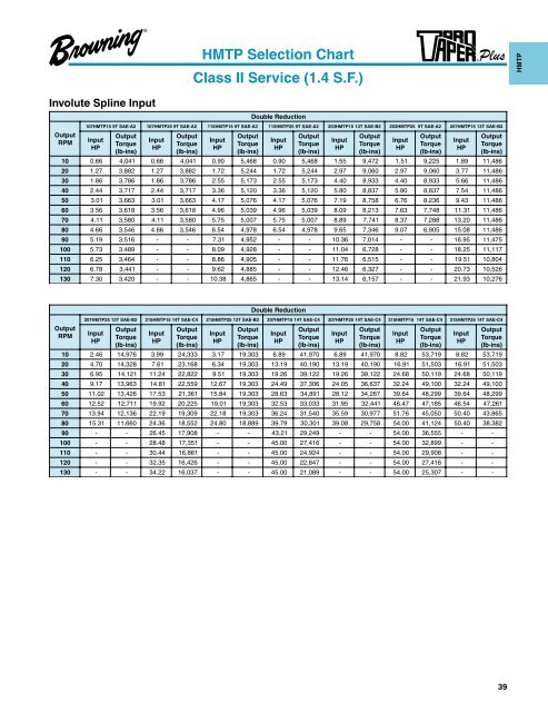
Involute Spline Input Output RPM HMTP Selection Chart Class II Service (1.4 S.F.) Double Reduction 107HMTP15 9T SAE-A2 107HMTP25 9T SAE-A2 115HMTP15 9T SAE-A2 115HMTP25 9T SAE-A2 203HMTP15 13T SAE-B2 203HMTP25 9T SAE-A2 207HMTP15 13T SAE-B2 Input HP Output Torque ( lb-ins) Input HP Output Torque ( lb-ins) Input HP Output Torque ( lb-ins) Input HP Output Torque ( lb-ins) Input HP Output Torque ( lb-ins) Input HP Output Torque ( lb-ins) Input HP Output Torque ( lb-ins) 10 0. 66 4, 041 0. 66 4, 041 0. 90 5, 468 0. 90 5, 468 1. 55 9, 472 1. 51 9, 225 1. 89 11, 486 20 1. 27 3, 882 1. 27 3, 882 1. 72 5, 244 1. 72 5, 244 2. 97 9, 060 2. 97 9, 060 3. 77 11, 486 30 1. 86 3, 786 1. 86 3, 786 2. 55 5, 173 2. 55 5, 173 4. 40 8, 933 4. 40 8, 933 5. 66 11, 486 40 2. 44 3, 717 2. 44 3, 717 3. 36 5, 120 3. 36 5, 120 5. 80 8, 837 5. 80 8, 837 7. 54 11, 486 50 3. 01 3, 663 3. 01 3, 663 4. 17 5, 076 4. 17 5, 076 7. 19 8, 758 6. 76 8, 236 9. 43 11, 486 60 3. 56 3, 618 3. 56 3, 618 4. 96 5, 039 4. 96 5, 039 8. 09 8, 213 7. 63 7, 748 11. 31 11, 486 70 4. 11 3, 580 4. 11 3, 580 5. 75 5, 007 5. 75 5, 007 8. 89 7, 741 8. 37 7, 288 13. 20 11, 486 80 4. 66 3, 546 4. 66 3, 546 6. 54 4, 978 6. 54 4, 978 9. 65 7, 346 9. 07 6, 905 15. 08 11, 486 90 5. 19 3, 516 - - 7. 31 4, 952 - - 10. 36 7, 014 - - 16. 95 11, 475 100 5. 73 3, 489 - - 8. 09 4, 928 - - 11. 04 6, 728 - - 18. 25 11, 117 110 6. 25 3, 464 - - 8. 86 4, 905 - - 11. 76 6, 515 - - 19. 51 10, 804 120 6. 78 3, 441 - - 9. 62 4, 885 - - 12. 46 6, 327 - - 20. 73 10, 526 130 7. 30 3, 420 - - 10. 38 4, 865 - - 13. 14 6, 157 - - 21. 93 10, 276 Output RPM Double Reduction 207HMTP25 13T SAE-B2 215HMTP15 14T SAE-C4 215HMTP25 13T SAE-B2 307HMTP15 14T SAE-C4 307HMTP25 14T SAE-C4 315HMTP15 14T SAE-C4 315HMTP25 14T SAE-C4 Input HP Output Torque ( lb-ins) Input HP Output Torque ( lb-ins) Input HP Output Torque ( lb-ins) Input HP Output Torque ( lb-ins) Input HP Output Torque ( lb-ins) Input HP Output Torque ( lb-ins) Input HP Output Torque ( lb-ins) 10 2. 46 14, 976 3. 99 24, 333 3. 17 19, 303 6. 89 41, 970 6. 89 41, 970 8. 82 53, 719 8. 82 53, 719 20 4. 70 14, 328 7. 61 23, 168 6. 34 19, 303 13. 19 40, 190 13. 19 40, 190 16. 91 51, 503 16. 91 51, 503 30 6. 95 14, 121 11. 24 22, 822 9. 51 19, 303 19. 26 39, 122 19. 26 39, 122 24. 68 50, 119 24. 68 50, 119 40 9. 17 13, 963 14. 81 22, 559 12. 67 19, 303 24. 49 37, 306 24. 05 36, 637 32. 24 49, 100 32. 24 49, 100 50 11. 02 13, 426 17. 53 21, 361 15. 84 19, 303 28. 63 34, 891 28. 12 34, 267 39. 64 48, 299 39. 64 48, 299 60 12. 52 12, 711 19. 92 20, 225 19. 01 19, 303 32. 53 33, 033 31. 95 32, 441 46. 47 47, 185 46. 54 47, 261 70 13. 94 12, 136 22. 19 19, 309 22. 18 19, 303 36. 24 31, 540 35. 59 30, 977 51. 76 45, 050 50. 40 43, 865 80 15. 31 11, 660 24. 36 18, 552 24. 80 18, 889 39. 79 30, 301 39. 08 29, 758 54. 00 41, 124 50. 40 38, 382 90 - - 26. 45 17, 908 - - 43. 21 29, 249 - - 54. 00 36, 555 - - 100 - - 28. 48 17, 351 - - 45. 00 27, 416 - - 54. 00 32, 899 - - 110 - - 30. 44 16, 861 - - 45. 00 24, 924 - - 54. 00 29, 908 - - 120 - - 32. 35 16, 426 - - 45. 00 22, 847 - - 54. 00 27, 416 - - 130 - - 34. 22 16, 037 - - 45. 00 21, 089 - - 54. 00 25, 307 - - 39 HMTP
- Page 1: Shaft Mount Worm Gear and Bevel Red
- Page 4 and 5: SMTP Shaft Mount TorqTaper Plus ®
- Page 6 and 7: The American Standard 4 Team Up wit
- Page 8 and 9: The New Way... Your Way 6 3 7 6 5 2
- Page 10 and 11: Note: See “Application Considerat
- Page 12 and 13: 10 Application AGMA Up to 3 Hours P
- Page 14 and 15: Output RPM 12 Reducer Size Minimum
- Page 16 and 17: Output RPM Reducer Size Minimum She
- Page 18 and 19: Output RPM 1/4 HP MOTOR 5 - 50 107S
- Page 20 and 21: Output RPM Reducer Size Minimum She
- Page 22 and 23: Output RPM 1/4 HP MOTOR 5 - 50 107S
- Page 24 and 25: Output RPM Reducer Size Minimum She
- Page 26 and 27: 24 C A G Shaft Mount Reducers SMTP
- Page 28 and 29: Part Number Explanation 407 SM TP 2
- Page 30 and 31: Application Inspired... Hydraulical
- Page 32 and 33: Example No. 1 Units 107 - 315 Hydra
- Page 34 and 35: 32 Application AGMA Up to 3 Hours P
- Page 36 and 37: Involute Spline Input 34 Output RPM
- Page 38 and 39: Straight Sided Spline Input 36 Outp
- Page 42 and 43: Straight Sided Spline Input 40 Outp
- Page 44 and 45: Involute Spline Input 42 Output RPM
- Page 46 and 47: Straight Sided Spline Input 44 Outp
- Page 48 and 49: 46 P1 P C UNIT NO. A G Reversible s
- Page 50 and 51: Innovative C-Face Motor Connections
- Page 52 and 53: Example No. 1 Units 107 - 315 C-fac
- Page 54 and 55: 52 Application AGMA Up to 3 Hours P
- Page 56 and 57: Output RPM 54 CMTP Selection Chart
- Page 58 and 59: Output RPM 56 CMTP Selection Chart
- Page 60 and 61: Output RPM 58 CMTP Selection Chart
- Page 62 and 63: 60 Reversible single bushing system
- Page 64 and 65: 62 2 3 1 4 5
- Page 66 and 67: REDUCER SIZE 107SMTP 115SMTP BUSHIN
- Page 68 and 69: REDUCER SIZE 307SMTP REDUCER SIZE 3
- Page 70 and 71: Browning shaft mount reducers may b
- Page 72 and 73: 9.00 * To determine usable input sh
- Page 74 and 75: 9.00 72 S L Motor Frame Size E N V
- Page 77 and 78: Browning Belt Drives For over 120 y
- Page 79 and 80: Accessories Shaft Mount Reducers Pr
- Page 81 and 82: Accessories Shaft Mount Reducers Pr
- Page 83 and 84: Accessories Shaft Mount Reducers Pr
- Page 85 and 86: Accessories Shaft Mount Reducers Pr
- Page 87 and 88: Accessories Shaft Mount Reducers Pr
- Page 89 and 90: Accessories Shaft Mount Reducers Pr
- Page 91 and 92:
Accessories Shaft Mount Reducers Pr
- Page 93 and 94:
Accessories Shaft Mount Reducers Pr
- Page 95 and 96:
Accessories Shaft Mount Reducers Pr
- Page 97 and 98:
Accessories Shaft Mount Reducers Pr
- Page 99 and 100:
Accessories Shaft Mount Reducers Pr
- Page 101 and 102:
Accessories Shaft Mount Reducers Pr
- Page 103 and 104:
Accessories Shaft Mount Reducers Pr
- Page 105 and 106:
Accessories Shaft Mount Reducers Pr
- Page 107 and 108:
Accessories Shaft Mount Reducers Pr
- Page 109 and 110:
Accessories Shaft Mount Reducers Pr
- Page 111 and 112:
Accessories Shaft Mount Reducers Pr
- Page 113 and 114:
Accessories Shaft Mount Reducers Pr
- Page 115 and 116:
Accessories Shaft Mount Reducers Pr
- Page 117 and 118:
Accessories Shaft Mount Reducers Pr
- Page 119 and 120:
Accessories Shaft Mount Reducers Pr
- Page 121 and 122:
Output rpm Accessories Shaft Mount
- Page 123 and 124:
Output rpm Accessories Shaft Mount
- Page 125 and 126:
Bushing guard kits have the followi
- Page 127 and 128:
STOCK SMTP REDUCER ( 1) Accessories
- Page 129 and 130:
STOCK HMTP REDUCER ( 1) Accessories
- Page 131 and 132:
STOCK CMTP REDUCER ( 1) Accessories
- Page 133 and 134:
REDUCER SIZE Accessories Shaft Moun
- Page 135 and 136:
Accessories Shaft Mount Reducers Op
- Page 137 and 138:
Shaft Mount Engineering Section Inp
- Page 139 and 140:
Output RPM 10 20 30 40 50 60 70 80
- Page 141 and 142:
SMTP, HMTP, CMTP Output Thrust and
- Page 143 and 144:
141 Shaft Mount Engineering SMTP, H
- Page 145 and 146:
Don’t Let An Ounce of Dirt Stop 1
- Page 147 and 148:
SMTP, HMTP, CMTP Face Mounting Dril
- Page 149 and 150:
SMTP, HMTP, CMTP Lubrication Sizes
- Page 151 and 152:
Output RPM AGMA Oil Viscosity Grade
- Page 153 and 154:
12.88 15.55 17.38 4.9375 Bore & 1.2
- Page 155 and 156:
Design Features 1. Rugged Cast Iron
- Page 157 and 158:
10 12 11 3 Accessories Need a reduc
- Page 159 and 160:
QH QHT QHF CH CHT CHF UHMT UHMB QHM
- Page 161 and 162:
Part Description Configuration Cent
- Page 163 and 164:
Example No. 2 - Torque Method Selec
- Page 165 and 166:
Up to 3-10 Over APPLICATION 3 Hrs.
- Page 167 and 168:
Unit Size Engineering Data Input Ho
- Page 169 and 170:
Engineering Data Input Horsepower,
- Page 171 and 172:
Complete Gearing Solutions... Emers
- Page 173 and 174:
Dimensions (Inches) for Style “U
- Page 175 and 176:
Worm Gear Reducers Dimensions (Inch
- Page 177 and 178:
Worm Gear Reducers Dimensions (Inch
- Page 179 and 180:
DIMENSIONS (INCHES) FOR STYLE “QT
- Page 181 and 182:
Dimensions (Inches) for Style “UV
- Page 183 and 184:
181 Raider Plus Dimensions (Inches)
- Page 185 and 186:
Fan Kit Ref. No. Fan Kit AA Tap Dee
- Page 187 and 188:
Worm Gear Reducers Dimensions (Inch
- Page 189 and 190:
Dimensions (Inches) for Style “CF
- Page 191 and 192:
Fan Kit Ref. No. Fan Kit A A Tap De
- Page 193 and 194:
CD UNIT SIZE N.E.M.A. FRAME A B C D
- Page 195 and 196:
Worm Gear Reducers Dimensions (Inch
- Page 197 and 198:
Worm Gear Reducers Dimensions (Inch
- Page 199 and 200:
C.D. COMPONENTS u PART NO. H FLANGE
- Page 201 and 202:
DIMENSIONS (INCHES) FOR STYLE “QH
- Page 203 and 204:
Fan Kit R ef. No. Fan Kit AA Tap De
- Page 205 and 206:
C. D. Dimensions (Inches) for Style
- Page 207 and 208:
Worm Gear Reducers Dimensions (Inch
- Page 209 and 210:
Dimensions (Inches) for Style “QH
- Page 211 and 212:
Worm Gear Reducers Dimensions (Inch
- Page 213 and 214:
Worm Gear Reducers Dimensions (Inch
- Page 215 and 216:
213 Raider Plus Dimensions (Inches)
- Page 217 and 218:
Worm Gear Reducers Dimensions (Inch
- Page 219 and 220:
Worm Gear Reducers Dimensions (Inch
- Page 221 and 222:
A C N.E.M.A. Frame Adapter Kit Kit
- Page 223 and 224:
D L C O E F M Dia. B A K N Dia. Dim
- Page 225 and 226:
Tack-On Reducers Off the shelf Tack
- Page 227 and 228:
R L R L L1 R1 Floor Mount Tack-On R
- Page 229 and 230:
Reducers Primary Secondary Output
- Page 231 and 232:
SECONDARY UNIT * Secondary Unit PRI
- Page 233 and 234:
Complete Gearing Solutions... Emers
- Page 235 and 236:
Washdown White epoxy paint • Prov
- Page 237 and 238:
1. Determine Service Factor From se
- Page 239 and 240:
Dimensions (Inches) for Style “QW
- Page 241 and 242:
Stainless Raider Plus Designed for
- Page 243 and 244:
How to Order Part Description Confi
- Page 245 and 246:
Up to 3-10 Over APPLICATION 3 Hrs.
- Page 247 and 248:
Stainless Raider Plus Input Horsepo
- Page 249 and 250:
KB AA C.D. HB N. E. M. A. Frame L J
- Page 251 and 252:
AA C.D. K H L J E C A W Key U T 8 H
- Page 253 and 254:
Stainless Accessories A C B G F DIA
- Page 255 and 256:
Design Features 1. Compact light-we
- Page 257 and 258:
Example No. 2 - Torque Method Selec
- Page 259 and 260:
Up to 3-10 Over APPLICATION 3 Hrs.
- Page 261 and 262:
UNIT SIZE ■ 690 RPM MECHANICAL In
- Page 263 and 264:
Making it move is our business. Whe
- Page 265 and 266:
Type QH CD Basic Unit NEMA Frame Wo
- Page 267 and 268:
Type UH CD CD Basic Unit Basic Unit
- Page 269 and 270:
3 1. Flange Kit • Industry standa
- Page 271 and 272:
Accessories Torqube Adapter Dimensi
- Page 273 and 274:
POWERGEAR ® W Series The RW and W
- Page 275 and 276:
Example No. 2 - Torque Method Selec
- Page 277 and 278:
Up to 3-10 Over APPLICATION 3 Hrs.
- Page 279 and 280:
Angle brackets shown are for illust
- Page 281 and 282:
Lubricating Instructions - Reducers
- Page 283 and 284:
Angle brackets are not included wit
- Page 285 and 286:
Worm Gear Reducers R-W and WD Serie
- Page 287 and 288:
Worm Gear Reducers W-DB and W-DV Sh
- Page 289 and 290:
Angle brackets are not included wit
- Page 291 and 292:
Angle brackets are not included wit
- Page 293 and 294:
291 POWERGEAR® PoweRgear s Inch-po
- Page 295 and 296:
Angle brackets are not included wit
- Page 297 and 298:
Angle brackets are not included wit
- Page 299 and 300:
297 POWERGEAR® PoweRgear s Inch-po
- Page 301 and 302:
299 POWERGEAR® PoweRgear s Inch-po
- Page 303 and 304:
301 POWERGEAR® PoweRgear s Inch-po
- Page 305 and 306:
303 POWERGEAR® PoweRgear s Inch-po
- Page 307 and 308:
305 POWERGEAR® PoweRgear 1.00 Serv
- Page 309 and 310:
POWERGEAR ® V Series The VX models
- Page 311 and 312:
Example No. 2 - Torque Method Selec
- Page 313 and 314:
Up to 3-10 Over APPLICATION 3 Hrs.
- Page 315 and 316:
Worm Gear Reducers DV and DVX Serie
- Page 317 and 318:
Lubricating Instructions - Reducers
- Page 319 and 320:
317 POWERGEAR® PoweRgear 1.00 Serv
- Page 321 and 322:
319 POWERGEAR® PoweRgear s Inch-po
- Page 323 and 324:
321 POWERGEAR® PoweRgear 1.00 Serv
- Page 325 and 326:
323 POWERGEAR® PoweRgear 1.00 Serv
- Page 327 and 328:
80VX Net wt. 895 lbs. 8.0" C.D. RAT
- Page 329 and 330:
327 POWERGEAR® PoweRgear s Inch-po
- Page 331 and 332:
POWERGEAR ® G Series The GC models
- Page 333 and 334:
Example No. 2 - Torque Method Selec
- Page 335 and 336:
POWERGEAR® (Service factors shown
- Page 337 and 338:
Model GC Type T Model GC Type V Sha
- Page 339 and 340:
Worm Gear Reducers GCDB, and GCDV S
- Page 341 and 342:
Worm Gear Reducers GDSA, and GDSF A
- Page 343 and 344:
Lubricating Instructions - Reducers
- Page 345 and 346:
Worm Gear Reducers GCDB and GCDV Se
- Page 347 and 348:
Worm Gear Reducers GCDB and GCDV Se
- Page 349 and 350:
Worm Gear Reducers GDSA and GDSF Se
- Page 351 and 352:
Worm Gear Reducers GCDB and GCDV Se
- Page 353 and 354:
Worm Gear Reducers GDSA and GDSF Se
- Page 355 and 356:
Worm Gear Reducers GCDB and GCDV Se
- Page 357 and 358:
Worm Gear Reducers GDSA and GDSF Se
- Page 359 and 360:
56C MOTOR FRAME A-.627 - .628 DIA.
- Page 361 and 362:
30GDSA Net wt. 72 lbs. 3.0" C.D. 30
- Page 363 and 364:
56C MOTOR FRAME A-.627 - .628 DIA.
- Page 365 and 366:
Worm Gear Reducers GDSA and GDSF Se
- Page 367 and 368:
56C MOTOR FRAME A-.627 - .628 DIA.
- Page 369 and 370:
Worm Gear Reducers GDSA and GDSF Se
- Page 371 and 372:
56C MOTOR FRAME A-.627 - .628 DIA.
- Page 373 and 374:
Worm Gear Reducers GDSA and GDSF Se
- Page 375 and 376:
182TC & 184TC MOTOR FRAME 56C MOTOR
- Page 377 and 378:
Worm Gear Reducers GDSA and GDSF Se
- Page 379 and 380:
17 5/8 11 1/8 Worm Gear Reducers 9
- Page 381 and 382:
22 7/8 15 1/8 Worm Gear Reducers 12
- Page 383 and 384:
POWERGEAR ® S Series The SA and SF
- Page 385 and 386:
Example No. 2 - Torque Method Selec
- Page 387 and 388:
Up to 3-10 Over APPLICATION 3 Hrs.
- Page 389 and 390:
MODEL DS TYPE A MODEL DS TYPE F No
- Page 391 and 392:
Lubricating Instructions - Reducers
- Page 393 and 394:
391 POWERGEAR® PoweRgear s Inch-po
- Page 395 and 396:
393 POWERGEAR® PoweRgear 1.00 Serv
- Page 397 and 398:
395 POWERGEAR® PoweRgear sInch-pou
- Page 399 and 400:
397 POWERGEAR® PoweRgear s Inch-po
- Page 401 and 402:
IRA Gearmotors 1. Innovative self-l
- Page 403 and 404:
General Presentation Type IRA Gener
- Page 405 and 406:
TEFC - Three Phase Corro-Duty TEFC
- Page 407 and 408:
Example IRA A right angle, foot mou
- Page 409 and 410:
Selection Example IRA A foot mounte
- Page 411 and 412:
MOTOR TYPE DESIGN S Single Phase TE
- Page 413 and 414:
AGMA Application Classification IRA
- Page 415 and 416:
F-1 STANDARD U-3* Mounting Position
- Page 417 and 418:
The IRA gearbox is filled at the fa
- Page 419 and 420:
General Specifications: Totally enc
- Page 421 and 422:
General Specifications: Totally enc
- Page 423 and 424:
General Specifications: Totally enc
- Page 425 and 426:
General Specifications: Totally enc
- Page 427 and 428:
M7 Insulation Standard 3 phase TEFC
- Page 429 and 430:
Overall dimensions Worm-Helical (GW
- Page 431 and 432:
Single Phase Gearmotor Alternate Mo
- Page 433 and 434:
DC FCR Brake (IP55) O P2 ØP AC AB
- Page 435 and 436:
IRA Worm and Helical Reducers These
- Page 437 and 438:
"C" Face Input Worm Gear Configurat
- Page 439 and 440:
Type Gear Frame IRA 6 20 Based on S
- Page 441 and 442:
AGMA Application Classification IRA
- Page 443 and 444:
AGMA Application Classification IRA
- Page 445 and 446:
Availability Gear Frame Footed Univ
- Page 447 and 448:
Exact ratio rpm, hp and Torque: IRA
- Page 449 and 450:
Exact ratio rpm, hp and Torque: IRA
- Page 451 and 452:
IRA Reducers Modifications Gear Mod
- Page 453 and 454:
Overall dimensions Standard W-3 Ass
- Page 455 and 456:
HB and HSB Bevel and Spiral Bevel 1
- Page 457 and 458:
455 Bevel Red. Cast Iron Load Class
- Page 459 and 460:
457 Bevel Red. Cast Iron Reducer Se
- Page 461 and 462:
459 Bevel Red. Cast Iron **The Inpu
- Page 463 and 464:
461 Bevel Red. Cast Iron Ratios, Ty
- Page 465 and 466:
ARA Aluminum Right Angle Bevel 1. L
- Page 467 and 468:
.630 P* U* SIZE 3ARA2 ONLY P1* .344
- Page 469 and 470:
M Series Spiral Bevel 1. Corrosion
- Page 471 and 472:
469 Bevel Red. M Series Load Classi
- Page 473 and 474:
Horizontal Mount W A C K H B Vertic
- Page 475 and 476:
Shaft Arrangements U - LR U - LR -O
- Page 477 and 478:
Emerson Industrial Automation Heavy
- Page 479 and 480:
Stainless Steel Motors 1. 1/2 - 2 H
- Page 481 and 482:
State-of-the-Art Features Built int
- Page 483 and 484:
C-Face IntelliGear Plus Innovative
- Page 485 and 486:
483 C-Face IntelliGear IntelliGear
- Page 487 and 488:
Color and state of indicator lamp S
- Page 489 and 490:
AZ C AG IntelliGear Plus C-Face Foo
- Page 491 and 492:
Decimal - Millimeter Equivalents F
- Page 493 and 494:
Put it all together. Our family of
- Page 495 and 496:
One Source Emerson Has the Industry
- Page 497 and 498:
All sales are made on our STANDARD
- Page 499 and 500:
EPT Edge Online is our online techn