FS1503 Installation Manual E (1855 KB) - Furuno USA
FS1503 Installation Manual E (1855 KB) - Furuno USA
FS1503 Installation Manual E (1855 KB) - Furuno USA

You also want an ePaper? Increase the reach of your titles
YUMPU automatically turns print PDFs into web optimized ePapers that Google loves.
1.3 Ground System<br />
A good antenna can work well only when it is connected to an efficient rf ground. Without a<br />
good ground system, the full potential of this radio cannot be realized.<br />
Ground for metallic hull<br />
CAUTION<br />
Ground the equipment to<br />
prevent electrical shock<br />
and mutual interference.<br />
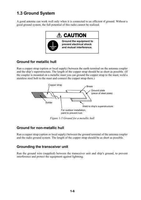
Run a copper strap (option or local supply) between the earth terminal on the antenna coupler<br />
and the ship’s superstructure. The length of the copper strap should be as short as possible. (If<br />
the coupler is mounted on a metallic mast you can ground the copper strap to the mast; weld a<br />
stainless steel bolt to the mast and connect the copper strap there.)<br />
Copper strap<br />
Solder<br />
Ground for non-metallic hull<br />
1-6<br />
Braze<br />
Ground plate<br />
(piece of steel plate)<br />
Weld to ship's superstructure.<br />
For outdoor installation,<br />
paint to prevent rust.<br />
Figure 1-5 Ground for a metallic hull<br />
Run a copper strap (option or local supply) between the ground terminal of the antenna coupler<br />
and the radio ground system. The length of the copper strap should be as short as possible.<br />
Grounding the transceiver unit<br />
Run the ground wire (supplied) between the transceiver unit and ship’s ground, to prevent<br />
interference and protect the equipment against lightning.