FS1503 Installation Manual E (1855 KB) - Furuno USA
FS1503 Installation Manual E (1855 KB) - Furuno USA
FS1503 Installation Manual E (1855 KB) - Furuno USA

You also want an ePaper? Increase the reach of your titles
YUMPU automatically turns print PDFs into web optimized ePapers that Google loves.
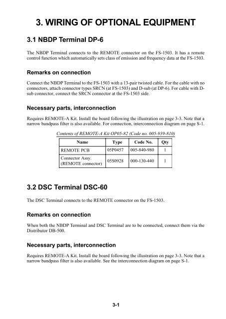
3. WIRING OF OPTIONAL EQUIPMENT<br />
3.1 NBDP Terminal DP-6<br />
The NBDP Terminal connects to the REMOTE connector on the FS-1503. It has a remote<br />
control function which automatically sets class of emission and frequency data at the FS-1503.<br />
Remarks on connection<br />
Connect the NBDP Terminal to the FS-1503 with a 13-pair twisted cable. For the cable with no<br />
connectors, attach connector types SRCN (at FS-1503) and D-sub (at DP-6). For cable with Dsub<br />
connector, connect the SRCN connector at the FS-1503 side.<br />
Necessary parts, interconnection<br />
Requires REMOTE-A Kit. Install the board following the illustration on page 3-3. Note that a<br />
narrow bandpass filter is also available. For connection, interconnection diagram on page S-1.<br />
Contents of REMOTE-A Kit OP05-82 (Code no. 005-939-810)<br />
Name T ype<br />
Code No.<br />
Qty<br />
REMOTE PCB 05P0457 005-840-980 1<br />
Connector<br />
Assy.<br />
( REMOTE<br />
connector)<br />
05S0928 000-130-440 1<br />
3.2 DSC Terminal DSC-60<br />
The DSC Terminal connects to the REMOTE connector on the FS-1503.<br />
Remarks on connection<br />
When both the NBDP Terminal and DSC Terminal are to be connected, connect them via the<br />
Distributor DB-500.<br />
Necessary parts, interconnection<br />
Requires REMOTE-A Kit. Install the board following the illustration on page 3-3. Note that a<br />
narrow bandpass filter is also available. See the interconnection diagram on page S-1.<br />
3-1