FS1503 Installation Manual E (1855 KB) - Furuno USA
FS1503 Installation Manual E (1855 KB) - Furuno USA
FS1503 Installation Manual E (1855 KB) - Furuno USA

You also want an ePaper? Increase the reach of your titles
YUMPU automatically turns print PDFs into web optimized ePapers that Google loves.
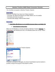
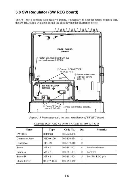
3.8 SW Regulator (SW REG board)<br />
The FS-1503 is supplied with negative ground. If necessary, to float the battery negative line,<br />
the SW REG Kit is available. Install the kit following the illustration below.<br />
J6<br />
J5<br />
2 Fasten SW. REG Board with five<br />
pan head screws-B (M3X8).<br />
J3<br />
J2<br />
SW. REG BOARD<br />
05P0668<br />
3 Fasten FETs with<br />
screw-A (M3 x 8).<br />
PA/FIL BOARD<br />
05P0667<br />
4 Connect CONNECTOR<br />
ASSY. (2 PCS.)<br />
5 Fasten shield cover<br />
with four screws<br />
J7<br />
(M3 x 6).<br />
J1<br />
3-5<br />
J2<br />
1 Place heat sheet on pedestal.<br />
Figure 3-5 Transceiver unit, top view, installation of SW REG Board<br />
Contents of SW REG Kit OP05-84 (Code no. 005-939-830)<br />
Name T ype<br />
Code No.<br />
Qty Remarks<br />
SWREG 05P0668 005-940-830 1<br />
Connector Assy.<br />
PH040-100 000-130-434 2<br />
Heat Sheet<br />
BFG-20 000-539-110 2<br />
Screw M3x6 000-881-103 4 For<br />
shield<br />
cover<br />
Screw-A M3x8 000-881-104 2 For<br />
FET<br />
Screw-B M3x8 000-881-404 5 For<br />
SW<br />
REG<br />
pcb<br />
Shield Cover<br />
05-077-1141 100-253-840 1