FS1503 Installation Manual E (1855 KB) - Furuno USA
FS1503 Installation Manual E (1855 KB) - Furuno USA
FS1503 Installation Manual E (1855 KB) - Furuno USA

You also want an ePaper? Increase the reach of your titles
YUMPU automatically turns print PDFs into web optimized ePapers that Google loves.
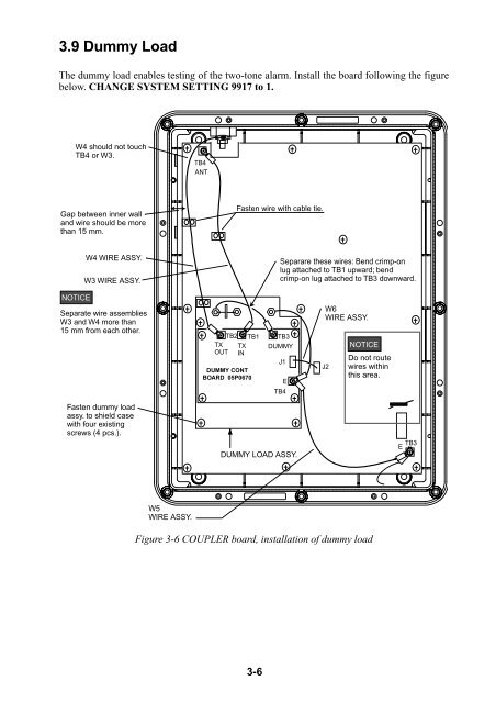
3.9 Dummy Load<br />
The dummy load enables testing of the two-tone alarm. Install the board following the figure<br />
below. CHANGE SYSTEM SETTING 9917 to 1.<br />
W4 should not touch<br />
TB4 or W3.<br />
Gap between inner wall<br />
and wire should be more<br />
than 15 mm.<br />
NOTICE<br />
W4 WIRE ASSY.<br />
W3 WIRE ASSY.<br />
Separate wire assemblies<br />
W3 and W4 more than<br />
15 mm from each other.<br />
Fasten dummy load<br />
assy. to shield case<br />
with four existing<br />
screws (4 pcs.).<br />
W5<br />
WIRE ASSY.<br />
TB4<br />
ANT<br />
TX<br />
OUT<br />
TB2 TB1 TB3<br />
DUMMY<br />
TX<br />
IN<br />
DUMMY CONT<br />
BOARD 05P0670<br />
Fasten wire with cable tie.<br />
3-6<br />
J1<br />
J<br />
E<br />
TB4<br />
DUMMY LOAD ASSY.<br />
Separare these wires: Bend crimp-on<br />
lug attached to TB1 upward; bend<br />
crimp-on lug attached to TB3 downward.<br />
W6<br />
WIRE ASSY.<br />
J2<br />
NOTICE<br />
Do not route<br />
wires within<br />
this area.<br />
Figure 3-6 COUPLER board, installation of dummy load<br />
E TB3