(WC) Wall Cantilever Jib Cranes - Spanco
(WC) Wall Cantilever Jib Cranes - Spanco
(WC) Wall Cantilever Jib Cranes - Spanco

You also want an ePaper? Increase the reach of your titles
YUMPU automatically turns print PDFs into web optimized ePapers that Google loves.
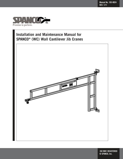
Installation and Maintenance Manual for<br />
SPANCO ® (<strong>WC</strong>) <strong>Wall</strong> <strong>Cantilever</strong> <strong>Jib</strong> <strong>Cranes</strong><br />
Manual No. 103-0024<br />
REV. 1/11<br />
ISO 9001 REGISTERED<br />
© SPANCO, Inc.
TABLE OF CONTENTS<br />
Forward...................................................................................................................... 4<br />
Installation.............................................................................................................. 5-7<br />
Maintenance and Inspection..................................................................................... 8-9<br />
Top & Bottom Bracket Assemblies: January 2011 and Earlier Only<br />
<strong>WC</strong> 100, 150, 250, 500 & 1000 LBS............................................................. 10-11<br />
Top & Bottom Bracket Assemblies: January 2011 and Later Only<br />
<strong>WC</strong> 100, 150, 250 & 500 LBS....................................................................... 12-13<br />
Top & Bottom Bracket Assemblies: January 2011 and Later Only<br />
<strong>WC</strong> 1000 Configuration...................................................................................14-15<br />
Bearing Assembly: Correct..........................................................................................16<br />
Bearing Assembly: Incorrect..................................................................................17-19<br />
Warranty and Service Policy........................................................................................20<br />
3
This manual contains important information to help you install, operate, maintain, and<br />
service your new jib crane. Please be sure to read this entire manual before installing or<br />
operating your crane. We also recommend that you obtain the latest issue of ANSI B30.11<br />
Safety Standard for Monorails and Underhung <strong>Cranes</strong> and study its contents thoroughly. By<br />
practicing the recommended maintenance suggestions, with proper installation, inspections,<br />
and application of correct operating procedures you will be assured maximum service from<br />
your jib crane and maximum safety for everyone. We also recommend obtaining a copy of<br />
the ‘CMAA Crane Operator’s Manual’ and studying its contents thoroughly.<br />
The jibs described in this manual are intended for indoor service. <strong>Jib</strong> cranes used for<br />
outdoor service require special consideration.<br />
Information contained in this manual is subject to change without notice.<br />
Before attempting to install your new jib crane, the following items must be understood:<br />
1. It is the customer’s responsibility to ensure that building columns or walls are adequate<br />
to support the crane and its rated load.<br />
2. <strong>Jib</strong> cranes should not be hung from any existing building structure without first<br />
consulting a qualified architect or engineer for the purpose of determining the<br />
structure’s adequacy.<br />
rWARNING !<br />
FORWARD<br />
Do not mount the jib crane to any structure unless you are sure the structure<br />
can safely support the loads imposed upon the structure. Failure to check<br />
this item can result in severe bodily injury or death.<br />
3. The installer is responsible for supplying the correct size, length, number, and type of<br />
bolts required to attach the jib crane brackets to the structure. SPANCO recommends<br />
that the bolts be ASTM A325 grade.<br />
4. Plan the installation such that the proper clearance as outlined in ANSI B30.11 will be<br />
adhered to. In the design of jib crane systems, all factors that influence clearances,<br />
such as wheel float and roof truss sag should be considered. <strong>WC</strong> jib cranes are<br />
designed for boom deflection at the tip of the boom to not exceed 1/225 of the span.<br />
4
INSTALLATION<br />
1. Refer to Tables (1) and (2) and locate the dimensions of the specific Model <strong>WC</strong> jib<br />
crane to be installed.<br />
TABLE<br />
(1)<br />
Boom and Trolley Depth<br />
5<br />
Span<br />
Capacity 4’ 6’ 8’ 10’ 12’ 14’ 16’<br />
100 6 1/2” 6 1/2” 11 1/4” 11 1/4” 13 1/4” 13 1/4” 13 1/4”<br />
150 6 1/2” 6 1/2” 11 1/4” 11 1/4” 13 1/4” 17” 17”<br />
250 6 1/2” 11 1/4” 11 1/4” 13 1/4” 17” 17” 17”<br />
500 12 5/8” 12 5/8” 15” 15” 17” 20 3/16” 20 3/16”<br />
1000 14 3/16” 14 3/16” 14 3/16” 17 1/16” 20 3/16” 24 1/8” 24 1/8”<br />
TABLE<br />
(2)<br />
Bracket Centers<br />
Span<br />
Capacity 4’ 6’ 8’ 10’ 12’ 14’ 16’<br />
100 36” 36” 36” 36” 48” 48” 48”<br />
150 36” 36” 36” 36” 48” 60” 60”<br />
250 36” 36” 36” 48” 60” 60” 60”<br />
500 36” 36” 48” 48” 60” 72” 84”<br />
1000 36” 36” 48” 48” 60” 72” 84”
INSTALLATION (Continued)<br />
1. Refer to Tables (1) and (2) and locate the dimensions of the specific Model <strong>WC</strong> <strong>Jib</strong><br />
crane to be installed.<br />
2. Please note that the bracket centers in the charts are nominal dimensions only. Do not<br />
drill holes according to these dimensions! The crane bushings and washers need a more<br />
precise fit, so be sure to follow the remaining steps!<br />
3. Note that the upper angles are slotted for adjustment and the lower angles only have<br />
holes. The bottom and top bearing assembly’s come pre-assembled with the attached<br />
angles. Verify that the top and bottom bearing assembly is assembled correct (see<br />
figures in this manual). Lift the crane into position using an overhead crane or other<br />
means. Place the bottom wall bracket against the supporting column in its proper<br />
location with a C-clamp or other supporting method. Drill the first lower hole and put<br />
the first bolt through. Level the lower bracket with a level and then drill the second<br />
lower hole. Put the second bolt through and then partially tighten the bolts. Do not fully<br />
tighten the bolts in case shims are needed (later).<br />
4. Allow crane to rest on lower bracket while still supporting the rest of the crane.<br />
5. Use a 3’ or 4’ level to level the crane vertically (to within 1/16” if using a plumb bob).<br />
Press downward on top of upper pin to ensure the upper bearing assembly is down as<br />
far as it goes. Level the upper bracket with a level and drill the two bracket holes into<br />
the support structure. Install and tighten the two upper bolts. Do not fully tighten the<br />
bolts in case shims are needed (later).<br />
6. Attach the hoist, supplied by others, to the hoist trolley. Use washers on hoist mounting<br />
pin to center hoist inside hoist trolley. Replace cotter pin(s) if worn or broken.<br />
rWARNING !<br />
NOTE: Some trolley load pins only have one cotter pin.<br />
Do not operate hoist or crane if cotter pins are not in place and properly<br />
bent over on both sides of hoist trolley. Check regularly that the cotter pins<br />
are in place and securing the hoist on the hoist trolley.<br />
6
INSTALLATION (Continued)<br />
7. Position the unloaded hoist and trolley at the extreme tip of the boom. If desired you<br />
may install the boom on a slight incline to compensate for anticipated deflection. If a<br />
slight incline is used it should be approximately 1/16” using a 36” level (see figure).<br />
This will keep the incline from exceeding ½ of the expected total boom tip deflection<br />
(1/2 x SPAN ÷ 225). If lower washers (shims) are required to level the boom, leave the<br />
upper bolts tightened, support crane as needed, and install bottom washers (shims) as<br />
needed, then retighten bottom bolts. If upper washers (shims) are required to level the<br />
boom, leave the lower bolts tightened, support crane as needed, and install upper<br />
washers (shims) as needed, then retighten upper bolts. In the end be sure all 4 bolts<br />
are properly tightened (approximately 154 FT*LBS).<br />
8. Recheck to make sure both upper and lower bearing assemblies will pass the first<br />
inspection (see correct figures in this manual). Test jib by rotating back and forth to<br />
ensure there is no unusual rubbing or binding or anything else unusual that could<br />
compromise the crane, bushings, or pin life. Be sure the crane rotates freely<br />
and unimpeded.<br />
9. Connect the hoist to its source of power (either air or electric) if required, as per the<br />
hoist manufacturer’s manual.<br />
10. Now that the jib crane installation is complete, but before the unit is placed into<br />
service, it is important to review and follow the procedures outlined in Chaper 11-2 of<br />
ANSI B30.11 regarding inspection, testing, and maintenance.<br />
11. Perform a first inspection (see the following pages titled (‘Maintenance and Inspections’).<br />
7
MAINTENANCE AND INSPECTION<br />
1. In order to minimize a potential injury or fatality, be sure every user performs his or her<br />
own inspection at the start of each shift, or at the time the crane is first used during<br />
each shift, unless the employer or supervisor has assigned this responsibility to another<br />
designated person to perform daily (see pages 19 and 20 of the CMAA Crane Operator’s<br />
Manual). This daily inspection is a visual inspection of the entire system before using it<br />
and note is taken of any unusual or abnormal operation of the system while using it.<br />
Meticulous, careful operation of the system will help minimize system repair<br />
and maintenance.<br />
2. Daily inspection items, according to the CMAA Crane Operator’s Manual, include a<br />
tagged out crane or hoist. Other daily items to check include control devices, hooks,<br />
hook latches, wire rope, oil leakage, unusual sounds, warning and safety labels. SPANCO<br />
recommends additional items to add to this daily list. Those items include bearings<br />
(bushings), pins, cotter pins, end stops and all nuts and bolts to be checked for<br />
tightness. Hoist trolleys should be checked for abnormal wear or breakage. Check that<br />
festoon trolleys travel smoothly through the track. Also check that all festoon cables<br />
and/or hoses are securely clamped to the festoon trolleys and end clamps. Check daily<br />
for anything unusual.<br />
3. The supplied bearings (bushings) are not designed to be lubricated. They are a wear<br />
item that will need to be inspected and eventually need to be replaced depending<br />
on usage.<br />
3. Refer to the figures in this manual showing correct and incorrect configurations of<br />
bearing assemblies. If there is a question concerning bearing assembly or any other item<br />
during the inspection, the crane must be tagged out of service immediately until all<br />
items are resolved.<br />
4. It is important to note that every system application and use will be different, therefore<br />
some conditions of use should require more frequent inspection. Examples of such<br />
conditions might be two or three shift operations, high, repetitive or fast movement of<br />
the crane, unusual working conditions, corrosive environments, or intended or<br />
unintended abuse.<br />
5. Remember end stops are emergency devices only. They are not to be used as an<br />
operational means to stop travel of the hoist (page 18 CMAA Crane Operator’s Manual).<br />
6. The hoist is not provided by SPANCO. The user should refer to the manual supplied for<br />
the hoist for a listing of maintenance points and their suggested frequency.<br />
7. Operating any crane has its potential dangers. To minimize injuries all users of this<br />
crane must be properly trained on its use and all users must be able to identify and<br />
monitor any potential hazards that may be present in the work environment.<br />
8. Weekly or monthly inspections would be more detailed inspections than what is<br />
described above.<br />
8
MAINTENANCE AND INSPECTION (Continued)<br />
9. A yearly inspection includes all of the above inspection items plus a partial tear down of<br />
the upper and lower bearing assemblies. Properly support the crane by an overhead<br />
crane or other means and remove the upper cotter pin and then remove the main pin<br />
(refer to the proper figures in this manual). The bearing will need to be removed and<br />
checked. It will either be a flanged or non-flanged sleeve bearing (bushing). If flanged,<br />
check the flange for any cracks or for any unusual or excessive wear. For any nonflanged<br />
bearing, remove and check for any wear. Also visually inspect the pin and cotter<br />
pin for any signs of unusual wear. Refer to the proper figures in this manual to be sure<br />
that the bearing assemblies go back together properly. After putting the top assembly<br />
back together, repeat the same process for the lower bearing assembly, making sure the<br />
crane is properly supported at all times. Contact SPANCO immediately concerning any<br />
possible replacement parts in question.<br />
9
TOP BRACKET ASSEMBLY:<br />
JANUARY 2011 AND EARLIER ONLY<br />
<strong>WC</strong> 100, 150, 250, 500 & 1000 LBS<br />
10
BOTTOM BRACKET ASSEMBLY:<br />
JANUARY 2011 AND EARLIER ONLY<br />
<strong>WC</strong> 100, 150, 250, 500 & 1000 LBS<br />
11
TOP BRACKET ASSEMBLY:<br />
JANUARY 2011 AND LATER ONLY<br />
<strong>WC</strong> 100, 150, 250 & 500 LBS<br />
12
BOTTOM BRACKET ASSEMBLY:<br />
JANUARY 2011 AND LATER ONLY<br />
<strong>WC</strong> 100, 150, 250 & 500 LBS<br />
13
TOP BRACKET ASSEMBLY:<br />
JANUARY 2011 AND LATER ONLY<br />
<strong>WC</strong> 1000 CONFIGURATION<br />
14
BOTTOM BRACKET ASSEMBLY:<br />
JANUARY 2011 AND LATER ONLY<br />
<strong>WC</strong> 1000 CONFIGURATION<br />
15
– Configuration for January 2011<br />
and earlier<br />
– All washers are installed and in the<br />
correct locations<br />
– Flange bearings are not beginning to pull<br />
out and are installed in the correct<br />
locations<br />
– Pin is down the whole way<br />
– Cotter pin is present<br />
– Angles and crane are aligned horizontally<br />
BEARING ASSEMBLY: CORRECT<br />
16<br />
– Configuration for January 2011<br />
and later<br />
– All washers are installed and in the<br />
correct locations<br />
– Flange bearings are not beginning to pull<br />
out and are installed in the correct<br />
locations<br />
– Pin is down the whole way<br />
– Cotter pin is present<br />
– Angles and crane are aligned horizontally
Inspection Procedure:<br />
– Crane must be taken out of service<br />
immediately<br />
– Could result in serious injury or death<br />
Problem:<br />
– The upper flange bearing is beginning to<br />
pull out<br />
– Flange bearing may be wearing<br />
incorrectly<br />
– Pin may be exposed to wear or failure if<br />
flange bearing pulls the entire way out<br />
Possible Cause:<br />
– Bracket centers are too large<br />
BEARING ASSEMBLY: INCORRECT<br />
17<br />
Inspection Procedure:<br />
– Crane must be taken out of service<br />
immediately<br />
– Could result in serious injury or death<br />
Problem:<br />
– Center washer is missing<br />
Possible Cause:<br />
– Incorrect installation
Inspection Procedure:<br />
– Crane must be taken out of service<br />
immediately<br />
– Could result in serious injury or death<br />
Problem:<br />
– Angles or crane are misaligned<br />
– Pin is beginning to pull out<br />
– Upper flange bearing may be beginning<br />
to pull out<br />
– Flange bearing may be wearing<br />
incorrectly<br />
– Upper portion of pin may be exposed to<br />
wear or failure due to misalignment<br />
Possible Cause:<br />
– Bracket not mounted correctly<br />
BEARING ASSEMBLY: INCORRECT<br />
18<br />
Inspection Procedure:<br />
– Crane must be taken out of service<br />
immediately<br />
– Could result in serious injury or death<br />
Problem:<br />
– Lower flange bearing is missing entirely<br />
– Angle will be wearing directly on pin<br />
without the protection of the bearing<br />
– Pin will prematurely fail<br />
Possible Cause:<br />
– Lower flange bearing is missing entirely<br />
(incorrect installation)<br />
– Bracket centers are less than required
Inspection Procedure:<br />
– Crane must be taken out of service<br />
immediately<br />
– Could result in serious injury or death<br />
Problem:<br />
– Upper flange bearing is missing entirely<br />
– Angle will be wearing directly on pin<br />
without the protection of the bearing<br />
– Pin will prematurely fail<br />
– The cotter pin is missing entirely<br />
– The pin is beginning to work its way out<br />
of its proper location<br />
BEARING ASSEMBLY: INCORRECT<br />
19<br />
– Configuration for January 2011<br />
and later<br />
– Although this figure looks identical to<br />
the correct configuration, there may be<br />
sleeve bearings that are missing for the<br />
1,000 LB crane<br />
– The thrust bearings are obviously here,<br />
but the sleeve bearings may or may not<br />
be present. A closer inspection would be<br />
necessary to determine if the sleeve<br />
bearings are present or not
FIVE-YEAR EQUIPMENT WARRANTY<br />
SPANCO offers this Equipment Warranty (the “Warranty”) on the following equipment:<br />
Manually propelled Free Standing and Ceiling Mounted Workstation Bridge <strong>Cranes</strong>.<br />
Manually propelled Monorails.<br />
Manually propelled ALU-TRACK Bridge <strong>Cranes</strong> and Monorails.<br />
Manually rotated Enclosed Track and I-Beam <strong>Jib</strong> <strong>Cranes</strong>.<br />
Manually propelled Gantries.<br />
Manually propelled Articulating <strong>Jib</strong> <strong>Cranes</strong>.<br />
ALL motorized SPANCO products come with a one year warranty on drive components.<br />
SPANCO warrants the Equipment and wearable end truck and trolley wheels only, to be free from defects in material and<br />
workmanship for a period of five (5) years or 10,000 hours (whichever occurs first), commencing on the date of shipment to the first<br />
retail purchaser (“Purchaser”). This Warranty does not extend to Equipment which has been subject to misuse, use in excess of rated<br />
capacity, negligent operation, use beyond SPANCO's published service factors, improper installation or maintenance, and does not<br />
apply to any Equipment which has been repaired or altered without SPANCO's written authorization. Written notice of any claimed<br />
defect must be given to SPANCO within thirty (30) days after such defect is discovered. SPANCO's obligation, and Purchaser's sole<br />
remedy under this Warranty is limited to, at SPANCO's discretion, the replacement or repair of the Equipment at SPANCO's factory or<br />
at a location approved by SPANCO. Purchaser is responsible for all freight and transportation costs relating to the repair or<br />
replacement of the Equipment. THE FOREGOING WARRANTY IS EXPRESSLY IN LIEU OF ALL OTHER WARRANTIES WHATSOEVER<br />
WHETHER EXPRESS, IMPLIED, OR STATUTORY. SELLER MAKES NO WARRANTY AS TO THE MERCHANTABILITY OR FITNESS FOR<br />
A PARTICULAR PURPOSE OF THE EQUIPMENT AND MAKES NO OTHER WARRANTY, EITHER EXPRESS OR IMPLIED. SPANCO shall<br />
not be liable, under any circumstances, for any indirect, special or consequential damages including, but not limited to, lost profits,<br />
increased operating costs or loss of production. This Warranty shall not extend to any components or accessories not manufactured by<br />
SPANCO (such as casters), and Purchaser's remedy for such components and accessories shall be determined by the terms and<br />
conditions of any warranty provided by the manufacturer of such components and accessories.<br />
SERVICE POLICY<br />
SPANCO, Inc.<br />
604 Hemlock Road<br />
Morgantown, PA, 19543<br />
1. Obtain as much information as possible concerning the problem through personal observation by yourself or other authorized personnel<br />
familiar with the job and equipment: include model, serial and/or part numbers, voltages, speeds and any other special identifying<br />
features. Be prepared to discuss the situation in detail.<br />
2. All authorized labor charges will be based on straight time. Hourly rates, estimated man hours, and not to exceed total dollar amount<br />
required for corrections are to be agreed upon before authorization is given. There will be no allowances for overtime except in dire<br />
emergencies and then only with prior approval.<br />
3. A verbal agreement may be reached immediately on both the method of correction and the approximate cost. A warranty authorization<br />
number will be assigned for the specific incident. A confirming written authorization will be forwarded to the distributor.<br />
4. The distributor must send an itemized invoice, showing our release number or invoice number and warranty authorization number after<br />
authorized corrections have been made. A credit memo will be issued by accounting after the invoice has been received and approved.<br />
Warranty charges ARE NOT to be deducted from outstanding open account invoices under any circumstances.<br />
5. Any field corrections made prior to an authorization by SPANCO will not be accepted as a warranty charge or the responsibility of<br />
SPANCO. Any modification to the equipment made without the prior approval of the seller will void all warranties. A verbal authorization<br />
for modification may be obtained, in which event a warranty authorization number will be assigned for the specific modification.<br />
A confirming written authorization will be forwarded to the distributor.<br />
This warranty and service policy will be incorporated as a permanent section of the current price book as issued by SPANCO.<br />
20<br />
spanco.com<br />
Toll Free: (800) 869-2080<br />
Local: (610) 286-7200<br />
Fax: (610) 286-0085