Field emission scanning electron microscopy a high-resolution ...
Field emission scanning electron microscopy a high-resolution ...
Field emission scanning electron microscopy a high-resolution ...

Create successful ePaper yourself
Turn your PDF publications into a flip-book with our unique Google optimized e-Paper software.
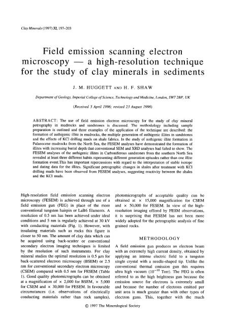
Clay Minerals (1997) 32, 197-203<br />
<strong>Field</strong> <strong>emission</strong> <strong>scanning</strong> <strong>electron</strong><br />
<strong>microscopy</strong> a <strong>high</strong>-<strong>resolution</strong> technique<br />
for the study of clay minerals in sediments<br />
J. M. HUGGETT AND H. F. SHAW<br />
Department of Geology, Imperial College of Science, Technology and Medicine, London, SW7 2BP, UK<br />
(Received 5 April 1996; revised 23 August 1996)<br />
ABSTRACT: The use of field <strong>emission</strong> <strong>electron</strong> <strong>microscopy</strong> for the study of clay mineral<br />
petrography in mudrocks and sandstones is discussed. The methodology including sample<br />
preparation is outlined and three examples of the application of the technique are described: the<br />
formation of authigenic illite in mudrocks, the multiple generation of authigenic illites in sandstones<br />
and the effects of KC1 drilling muds on shale fabrics. In the study of authigenic illite formation in<br />
Palaeocene mudrocks from the North Sea, the FESEM analyses have demonstrated the formation of<br />
illites with increasing burial depth that conventional SEM and XRD analyses had failed to show. The<br />
FESEM analyses of the authigenic illites in Carboniferous sandstones from the southern North Sea<br />
revealed at least three different habits representing different generation episodes rather than one illite<br />
formation event.This has important repercussions with regard to the interpretation of stable isotope<br />
and dating data for the illites. Significant petrographic changes in shales after treatment with KCI<br />
drilling muds have been observed from FESEM analyses, suggesting reactivity between the shales<br />
and the KC1 muds.<br />
High-<strong>resolution</strong> field <strong>emission</strong> <strong>scanning</strong> <strong>electron</strong><br />
<strong>microscopy</strong> (FESEM) is achieved through use of a<br />
field <strong>emission</strong> gun (FEG) in place of the more<br />
conventional tungsten hairpin or LaB6 filaments. A<br />
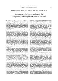
<strong>resolution</strong> of 0.5 nm has been achieved under ideal<br />
conditions and 5 nm is regularly achieved at 30 kV<br />
with conducting materials (Fig. 1). However, with<br />
insulating materials such as rocks this figure is<br />
closer to 50 nm. The amount of clay data which can<br />
be acquired using back-scatter or conventional<br />
secondary <strong>electron</strong> imaging techniques is limited<br />
by the <strong>resolution</strong> of such instruments. For clay<br />
mineral studies the optimal <strong>resolution</strong> is 0.5 p.m for<br />
back-scattered <strong>electron</strong> <strong>microscopy</strong> (BSEM) or 2.5<br />
nm for conventional secondary <strong>electron</strong> <strong>microscopy</strong><br />
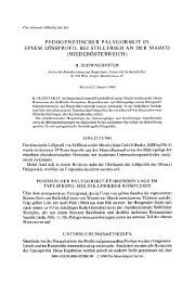
(CSEM) compared with 0.5 nm for FESEM (Table<br />
1). Good quality photomicrographs can be obtained<br />
at a magnification of x 2,000 for BSEM, x 5,000<br />
for CSEM and x 30,000 for FESEM. In favourable<br />
circumstances (i.e. observations of electrically<br />
conducting materials rather than rock samples),<br />
9 1997 The Mineralogical Society<br />
photomicrographs of acceptable quality can be<br />
obtained at x 15,000 magnification for CSEM<br />
and 50,000 for FESEM. In view of the <strong>high</strong>-<br />
<strong>resolution</strong> imaging offered by FESM observations,<br />
it is surprising that FESEM has not been more<br />
widely adopted for the petrographic analysis of fine<br />
grained rocks.<br />
METHODOLOGY<br />
A field <strong>emission</strong> gun produces an <strong>electron</strong> beam<br />
with an extremely <strong>high</strong> current density, obtained by<br />
applying an intense electric field to a tungsten<br />
single crystal with a needle-shaped tip. Unlike the<br />
conventional thermal <strong>emission</strong> gun this requires<br />
ultra <strong>high</strong> vacuum (10 -1~ Torr). The FEG is often<br />
referred to as the <strong>high</strong> brightness gun because the<br />
<strong>emission</strong> source for <strong>electron</strong>s is extremely small<br />
and because the number of <strong>electron</strong>s emitted per<br />
unit area is much greater than with other types of<br />
<strong>electron</strong> guns. This, together with the much
198 J. M. Huggett and H. F. Shaw<br />
50-<br />
(nm)<br />
~10<br />
"-I<br />
O<br />
03<br />
CE<br />
1 9<br />
W-hairpin filament<br />
LaBs<br />
FEG<br />
I I I I I I I<br />
5 10 15 20 25 30 35<br />
Accelerating voltage (kV)<br />
FIG. 1. Accelerating voltage vs. <strong>resolution</strong> for different types of <strong>electron</strong> source (JEOL, 1994).<br />
narrower range of emitted <strong>electron</strong> energies than is<br />
obtained with thermal <strong>emission</strong> guns, permits <strong>high</strong><br />
<strong>resolution</strong> at low kV (Fig. 1). The ability to work at<br />
low kV is particularly valuable for ultra-thin clay<br />
mineral particles which would appear to be<br />
'<strong>electron</strong> transparent' at <strong>high</strong> kV. For FESEM<br />
examination it is not always necessary to apply a<br />
conductive coating, particularly if working at very<br />
low kV, but for most clay work 10 kV is about the<br />
optimum and a conductive coating is preferred. The<br />
specimens should have either gold-palladium or<br />
platinum coatings of 30-40 nm thickness as the<br />
gold coating used in conventional SEM is too<br />
coarse and can be observed as a mosaic-like pattern<br />
on the sample surface thus obscuring morphological<br />
features. This is demonstrated by comparing the<br />
micrographs in Figs. 2 and 3. A Polaron 5000 series<br />
coater with a two minute coating time and normal<br />
FIG. 2. FESEM of chlorite-smectite in a Palaeocene mudrock. This sample was coated with gold rather than<br />
platinum and the mosaic-like pattern of the coating is clearly visible on all surfaces.
0<br />
e~<br />
9<br />
9<br />
e.<br />
9<br />
==<br />
9<br />
o<br />
e~<br />
9<br />
9<br />
e.<br />
.o<br />
.&<br />
e.<br />
o<br />
<<br />
e~<br />
.o<br />
Z<br />
<strong>Field</strong> <strong>emission</strong> <strong>electron</strong> <strong>microscopy</strong><br />
C) eq<br />
9 o<br />
0 o<br />
o<br />
~ 6<br />
o<br />
.~ o<br />
.~ .o<br />
r<br />
:><br />
r<br />
[I<br />
II<br />
g2<br />
9<br />
II<br />
199
200 J. M. Huggett and H. F. Shaw<br />
~l~tm<br />
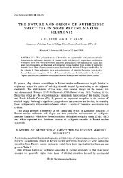
Fro. 3. Micrographs of a Palaeocene mudrock succession, central North Sea. (A) BSEM of a mudrock buried to<br />
2 kin. Organic matter (black) and mica (e.g. arrow) define the laminated fabric. The diffuse matrix is<br />
predominantly clay, but individual particles are not resolved; (B) CSEM of same mudrock sample shown in (A);<br />
(C) FESEM image of the same sample as (B); (D) CSEM of mudrock buried to approximately 3 km; (E) FESEM<br />
image of the same sample as (D), showing 'illitic' overgrowths not visible at the lower magnification;<br />
(F) HRTEM lattice fringe image of illite plate with overgrowth shown in (E) nucleated at a dislocation site in the<br />
plate.
esistance at 20 mA, was used to provide the gold-<br />
palladium and platinum coatings.<br />
The <strong>electron</strong> microscopes used in our studies<br />
were a JEOL 6400F with an Oxford Instruments<br />
<strong>high</strong> purity germanium energy dispersive X-ray<br />
detector at the Centre for Microscopy and<br />
Microanalysis, University of Queensland, and a<br />
Hitachi $800 (without a microanalyser) at the<br />
Natural History Museum, London.<br />
EXAMPLES<br />
Authigenic illite formation in mudrocks<br />
Until recently, X-ray diffraction (XRD) has been<br />
the principal investigative tool in mudrock diagen-<br />
esis, with the result that identification of authigenic<br />
minerals has often been by inference rather than<br />
observation. Now, FESEM, BSEM, CSEM and<br />
<strong>high</strong>-<strong>resolution</strong> transmission <strong>electron</strong> <strong>microscopy</strong><br />
(HRTEM) have been used to examine Palaeocene<br />
mudrocks from a North Sea well, which have been<br />
buried to between 2 and 3 km (see Huggett, 1995).<br />
The XRD analysis of the clay fractions of these<br />
mudrocks indicates that they are composed<br />
predominantly of illite and illite-smectite, with<br />
minor kaolinite and chlorite. The composition of<br />
the illite-smectite is typically 40-50% smectite and<br />
is regularly interstratified. The texture and relation-<br />
ships between the matrix, silt-size grains and<br />
organic matter are best observed in BSEM images<br />
(Fig. 3a). However, from Fig. 3a it is clear that<br />
BSEM is inadequate to observe individual clay<br />
particles. At 2 km depth the clay comprises flakes<br />
with the ragged appearance typical of detrital clay<br />
in both CSEM (Fig. 3b) and FESEM images<br />
(Fig. 3c). At ~ 3 km depth the clay fabric appears<br />
indistinguishable in CSEM images from that seen at<br />
2 km (Fig. 3d). However, in FESEM images of<br />
samples at 3 km depth, wispy overgrowths on illitic<br />
clay particles are a ubiquitous, if minor, component<br />
of the mudrocks (Fig. 3e). The precise chemical<br />
composition of these particles is uncertain as the<br />
particles were too small for collection of X-ray<br />
spectra, though HRTEM lattice fringe images<br />
confirm that they are indeed illite overgrowths on<br />
platy particles (Fig. 3f). The FESEM examination<br />
of samples from intermediate depths indicates that<br />
there is an overall increase in the proportion of<br />
wispy clay overgrowths with depth. The FESEM<br />
analyses have thus revealed the formation of<br />
diagenetic illites in these mudrocks that increases<br />
<strong>Field</strong> <strong>emission</strong> <strong>electron</strong> <strong>microscopy</strong> 201<br />
with depth, which conventional XRD and SEM<br />
analysis had previously failed to show.<br />
Multiple generations (?) of authigenic fibrous<br />
illite in sandstones<br />
The FESEM examination of authigenic fibrous<br />
illite in Westphalian sandstones from wells in the<br />
southern North Sea has revealed the existence of at<br />
least three morphological types (Figs. 4a & b).<br />
Previous conventional SEM analysis of these<br />
samples had not revealed these variations in illite<br />
morphology. It is possible that these morphological<br />
variations represent different generations of illite<br />
formation. If this interpretation is correct, it could<br />
have important petrographic significance regarding<br />
authigenic illite formation. It could also affect the<br />
interpretation of K/Ar dating and stable isotope<br />
analyses of authigenic illite separates. Such<br />
analyses are made on the basis that the separated<br />
illites represent a single illite formation event in<br />
any one sample. The FESEM observations of the<br />
illites in the Westphalian sandstones show that there<br />
could be several illite formation events.<br />
Effects of KC1 drilling muds on shale fabrics<br />
The effects of KC1 drilling muds on a range of<br />
shales were examined during work carried out<br />
jointly with Eniricerche in Milan, Italy. Figures 5a<br />
and b show samples of a shale composed<br />
predominantly of detrital illite-smectite, examined<br />
before and after being reacted with KC1 drilling<br />
mud at 60~ for two weeks. One effect of the<br />
treatment is shown in Fig. 5b with small fibrous<br />
overgrowths on the platy illite-smectite particles.<br />
The composition of the fibrous overgrowths is<br />
uncertain, as they are too small to be analysed in<br />
situ or to be separated for XRD analysis. Small and<br />
co-workers have demonstrated how fibrous and<br />
platy illite can be grown experimentally in<br />
sandstones in the presence of K-beating solutions<br />
(Small et al., 1992; Small & Manning, 1993). Using<br />
these experimental data as a precedent, it seems<br />
possible that the KC1 muds might have interacted<br />
with the detrital illite-smectite to produce the<br />
fibrous (illitic?) clay overgrowths observed in the<br />
FESEM photomicrographs. However, all that can be<br />
reported here is the observation of these fibrous<br />
overgrowths and any interpretation of the processes<br />
leading to their formation can only be conjectural at<br />
this stage.
202 J. M. Huggett and H. F. Shaw<br />
FIc. 4. FESEM micrographs of illitic clays in Westphalian sandstones from the southern North Sea. (A) Spectrum<br />
of illite morphologies: A -- bladed illite; B -- composite bladed illite; C -- platy illite. Fibrous illite arrowed.<br />
(B) Detail of area adjacent to B in Fig. 4a showing bladed illite (I) and a later generation of cross-cutting fibrous<br />
illites (black arrow) and what appears to be tabular (coalesced plates?) morphologies (arrowed 2).<br />
FIG. 5. FESEM micrographs of a shale (A) before and (B) after treatment with KCI drilling fluid at 60~ for two<br />
weeks.
<strong>Field</strong> <strong>emission</strong> <strong>electron</strong> <strong>microscopy</strong> 203<br />
CONCLUSIONS REFERENCES<br />
In this paper we have attempted to demonstrate the<br />
usefulness of FESEM for the study of clay fabrics<br />
in sedimentary rocks. The better <strong>resolution</strong> of the<br />
FESEM gives it significant advantages over<br />
CSEM and BSEM for the detailed observation of<br />
clay fabrics. Apart from adding to our knowledge<br />
of the clay petrography, these more detailed<br />
observations can also influence how we interpret<br />
other types of clay data, e.g. the isotopic and K/At<br />
of illites.<br />
ACKNOWLEDGMENTS<br />
Work using the JEOL 6400F at the University of<br />
Queensland Centre for Microscopy and Microanalysis<br />
was carried out by JMH during a visit funded by the<br />
British Council. Sue Barnes of the Natural History<br />
Museum (London) is thanked for assistance with the<br />
FESEM work done there. We should also like to thank<br />
Dr Luigi Cononico of Eniricerche SpA Milan and Dr<br />
John Berry for allowing us to use photomicrographs<br />
from their studies.<br />
Huggett J.M. (1995) Formation of authigenic illite in<br />
Palaeocene mudrocks from the Central North Sea: a<br />
study by <strong>high</strong> <strong>resolution</strong> <strong>electron</strong> <strong>microscopy</strong>. Clays<br />
Clay Miner. 43, 682-692.<br />
JEOL (1994) Multipurpose digital FE SEM. Product<br />
Information Document SM21.<br />
Mackinnon I.D.R. (1990) Introduction to <strong>electron</strong> beam<br />
techniques. Pp. 2-13 in: Electron-Optical Methods<br />
in Clay Science, CMS Workshop Lectures 2 (I.D.R.<br />
Mackinnon, editor) Clay Minerals Society, Boulder,<br />
Co., USA.<br />
Small J.S., Hamilton D.L. & Habesch S. (1992)<br />
Experimental simulation of clay precipitation within<br />
reservoir sandstones 2: mechanisms of illite forma-<br />
tion and controls on morphology. J. Sed. Pet. 62,<br />
520-529.<br />
Small J.S. & Manning D.A.C. (1993) Laboratory<br />
reproduction of morphological variation in petro-<br />
leum reservoir clays; monitoring of fluid composi-<br />
tion during illite precipitation. Pp. 181-212 in:<br />
Geochemistry of Clay-Pore Fluid Interactions<br />
(D.A.C. Manning, P.L.Hall & C.R. Hughes, editors)<br />
The Mineralogical Society Series No 4, Chapman &<br />
Hall.