Selectable Output Strobe and Horn/Strobes - System Sensor
Selectable Output Strobe and Horn/Strobes - System Sensor
Selectable Output Strobe and Horn/Strobes - System Sensor

You also want an ePaper? Increase the reach of your titles
YUMPU automatically turns print PDFs into web optimized ePapers that Google loves.
A u d i b l e / V i s i b l e N o t i f i c A t i o N<br />
<strong>Selectable</strong> <strong>Output</strong> <strong>Strobe</strong><br />
<strong>and</strong> <strong>Horn</strong>/<strong>Strobe</strong>s<br />
Models Available<br />
<strong>Strobe</strong>s<br />
Red White<br />
S1224MC S1224MCW<br />
S1224MCP S1224MCPW<br />
S1224MCK<br />
S1224MCSP<br />
<strong>Horn</strong>/<strong>Strobe</strong>s<br />
Red White<br />
P1224MC P1224MCW<br />
P1224MCP P1224MCPW<br />
P1224MCK<br />
P1224MCSP<br />
<strong>Horn</strong>s<br />
Red White<br />
H12/24 H12/24W<br />
H12/24K<br />
Product Overview<br />
Operates on either 12V or 24V<br />
Widest range of c<strong>and</strong>ela options:<br />
12V: 15 <strong>and</strong> 15/75 c<strong>and</strong>ela<br />
24V: 15, 15/75, 30, 75, 110 c<strong>and</strong>ela<br />
Easy c<strong>and</strong>ela selection<br />
Lower current draw<br />
Easy DIP switch selection for horn<br />
options<br />
Easy mounting with QuickClick<br />
Synchronizable with MDL<br />
Sync•Circuit module<br />
Meets UL1971, NFPA72, <strong>and</strong> ADA<br />
signaling requirements<br />
All strobe <strong>and</strong> horn/strobe models incorporate<br />
a new patented voltage booster design that has<br />
a more consistent flash bulb voltage over the<br />
range of c<strong>and</strong>ela selections. The benefit to the<br />
customer is a high quality strobe device.<br />
7125-1209:222<br />
7135-1209:223<br />
3014150<br />
S5512<br />
S4011<br />
122-02-E<br />
126-02-E<br />
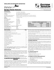
S1224MC <strong>Strobe</strong><br />
P1224MC <strong>Horn</strong>/<strong>Strobe</strong><br />
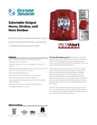
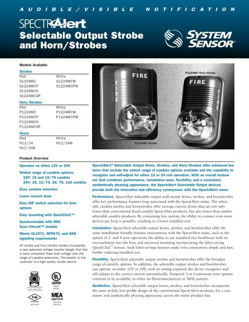
SpectrAlert ® <strong>Selectable</strong> <strong>Output</strong> <strong>Horn</strong>s, <strong>Strobe</strong>s, <strong>and</strong> <strong>Horn</strong>/<strong>Strobe</strong>s offer enhanced features<br />
that include the widest range of c<strong>and</strong>ela options available <strong>and</strong> the capability to<br />
recognize <strong>and</strong> self-adjust for either 12 or 24 volt operation. With an overall feature<br />
set that combines performance, installation ease, flexibility, <strong>and</strong> a consistent,<br />
aesthetically pleasing appearance, the SpectrAlert <strong>Selectable</strong> <strong>Output</strong> devices<br />
provide both the innovation <strong>and</strong> efficiency synonymous with the SpectrAlert name.<br />
Performance. SpectrAlert selectable output wall-mount horns, strobes, <strong>and</strong> horn/strobes<br />
offer key performance features long associated with the SpectrAlert name. The selectable<br />
c<strong>and</strong>ela strobes <strong>and</strong> horn/strobes offer average current draws that are not only<br />
lower than conventional fixed-c<strong>and</strong>ela SpectrAlert products, but also lower than similar<br />
selectable c<strong>and</strong>ela products. By consuming less current, the ability to connect even more<br />
devices per loop is possible, resulting in a lower installed cost.<br />
Installation. SpectrAlert selectable output horns, strobes, <strong>and</strong> horn/strobes offer the<br />
same installation-friendly features synonymous with the SpectrAlert name, such as the<br />
option of 2- <strong>and</strong> 4-wire operation; the ability to use st<strong>and</strong>ard size backboxes with no<br />
encroachment into the box; <strong>and</strong> universal mounting incorporating the labor-saving<br />
QuickClick feature. Such labor-savings features make wire connections simple <strong>and</strong> fast,<br />
further reducing installed cost.<br />
Flexibility. SpectrAlert selectable output strobes <strong>and</strong> horn/strobes offer the broadest<br />
range of c<strong>and</strong>ela options. In addition, the selectable output strobes <strong>and</strong> horn/strobes<br />
can operate on either 12V or 24V, with no setting required; the device recognizes <strong>and</strong><br />
self-adjusts to the correct current automatically. Temporal 3 or Continuous tone options<br />
continue to be available, in either an Electromechanical or 3kHz pattern.<br />
Aesthetics. SpectrAlert selectable output horns, strobes, <strong>and</strong> horn/strobes incorporate<br />
the same stylish, low profile design of the conventional SpectrAlert products, for a consistent<br />
<strong>and</strong> aesthetically pleasing appearance across the entire product line.
Engineering Specifications<br />
General<br />
SpectrAlert horns, strobes <strong>and</strong> horn/strobes shall be capable of<br />
mounting to a st<strong>and</strong>ard 4˝ × 4˝ × 1 1 /2˝ back box or a single gang<br />
2˝ × 4˝ × 1 7 /8˝ back box using the universal mounting plate<br />
included with each SpectrAlert product. Also, SpectrAlert products,<br />
when used in conjunction with the accessory Sync•Circuit<br />
Module, shall be powered from a non-coded power supply<br />
<strong>and</strong> shall operate on 12 or 24 volts. 12 volt rated devices shall<br />
have an operating voltage range of 9–17.5 volts. 24-volt rated<br />
devices shall have an operating voltage range or 17–33 volts.<br />
SpectrAlert products shall have an operating temperature of<br />
32° to 120°F <strong>and</strong> operate from a regulated DC or full wave<br />
rectified, unfiltered power supply.<br />
<strong>Strobe</strong><br />
<strong>Strobe</strong> shall be a <strong>System</strong> <strong>Sensor</strong> SpectrAlert Model _______<br />
listed to UL 1971 <strong>and</strong> be approved for fire protective service. The<br />
strobe shall be wired as a primary signaling notification appliance<br />
<strong>and</strong> comply with the Americans with Disabilities Act requirements<br />
for visible signaling appliances, flashing at 1Hz over the<br />
strobe’s entire operating voltage range. The strobe light shall consist<br />
of a xenon flash tube <strong>and</strong> associated lens/reflector system.<br />
<strong>Horn</strong>/<strong>Strobe</strong> Combination<br />
<strong>Horn</strong>/<strong>Strobe</strong> shall be a <strong>System</strong> <strong>Sensor</strong> SpectrAlert Model<br />
_______ listed to UL 1971 <strong>and</strong> UL 464 <strong>and</strong> shall be approved for<br />
Specifications<br />
Walk Test<br />
SpectrAlert horn/strobe <strong>and</strong> horn only<br />
work on “walk tests” with time durations<br />
of 4 seconds or greater<br />
Input Terminals<br />
12 to 18 AWG<br />
Dimensions<br />
<strong>Strobe</strong> <strong>and</strong> horn/strobe with universal<br />
plate<br />
5˝ × 5 5 /8˝ × 2 15 /16˝<br />
<strong>Strobe</strong> <strong>and</strong> horn/strobe with small<br />
footprint plate<br />
3 3 /8˝ × 5 5 /8˝ × 2 5 /16˝<br />
<strong>Horn</strong> with universal mounting plate<br />
5˝ × 5 5 /8˝ × 1 5 /16˝<br />
<strong>Horn</strong> without mounting plate<br />
2 15 /16˝ × 5 5 /16˝ × 1 5 /16˝<br />
Weight, horn only<br />
7.2 oz.<br />
Weight, strobe <strong>and</strong> horn/strobe<br />
8.8 oz.<br />
Mounting<br />
4˝ × 4˝ × 1 1 /2˝ or 2˝ × 4˝ × 1 7 /8˝<br />
st<strong>and</strong>ard boxes<br />
Operating Temperature (Indoor)<br />
32°F to 120°F (0°C to 49°C)<br />
Maximum humidity (Indoor)<br />
95% as tested per UL464<br />
Outdoor (K Series) Operating Temperature<br />
–40°F to 151°F<br />
(–40°C to 66°C)<br />
Outdoor rating<br />
NEMA 3R (per UL 50)<br />
fire protective service. <strong>Horn</strong>/strobe shall be wired as a primary<br />
signaling notification appliance <strong>and</strong> comply with the Americans<br />
with Disabilities Act requirements for visible signaling appliances,<br />
flashing at 1Hz over the strobe’s entire operating voltage range.<br />
The strobe light shall consist of a xenon flash tube <strong>and</strong> associated<br />
lens/reflector system. The horn shall have two tone options, two<br />
audibility options (at 24 volts) <strong>and</strong> the option to switch between<br />
a temporal 3 pattern <strong>and</strong> a non-temporal continuous pattern.<br />
<strong>Strobe</strong>s shall be powered independently of the sounder with the<br />
removal of factory installed jumper wires. The horn on horn/<br />
strobe models shall operate on a coded or non-coded power supply<br />
(the strobe must be powered continuously).<br />
Synchronization Module<br />
Module shall be a <strong>System</strong> <strong>Sensor</strong> Sync•Circuit _______ listed<br />
to UL 464 <strong>and</strong> shall be approved for fire protective service. The<br />
module shall synchronize SpectrAlert strobes at 1Hz <strong>and</strong> horns<br />
at temporal 3. Also, the module shall silence the horns on horn/<br />
strobe models, while operating the strobes, over a single pair of<br />
wires. The module shall be capable of mounting to a 4 11 /16˝ ×<br />
4 11 /16˝ × 2 1 /8˝ back box <strong>and</strong> shall control two Style Y (class B) or<br />
one Style Z (class A) circuit. Module shall be capable of multiple<br />
zone synchronization by daisy chaining multiple modules together<br />
<strong>and</strong> re-synchronizing each other along the chain. The module<br />
shall not operate on a coded power supply.<br />
Voltages<br />
12 or 24VDC <strong>and</strong> FWR 1 unfiltered<br />
Operating voltage range<br />
12V: 8–17.5V; 24V: 16–33V<br />
Operating voltage range (with<br />
Sync•Circuit module, MDL) 2<br />
12V: 9–17.5V; 24V: 17–33V<br />
U.S. Patent Numbers<br />
5,593,569<br />
5,914,665<br />
6,049,446<br />
Notes:<br />
1. Full Wave Rectified (FWR) voltage is a non-regulated, time-varying power source that is used on some power supply <strong>and</strong> panel outputs.<br />
2. The MDL causes a one-volt voltage drop in the notification appliance circuit.
Table 1-A: SpectrAlert <strong>Strobe</strong> UL Max. Current Draw<br />
FWR Operating<br />
DC Operating<br />
Current–<strong>Strobe</strong><br />
Current–<strong>Strobe</strong><br />
C<strong>and</strong>ela<br />
(mA RMS)<br />
(mA RMS)<br />
Setting<br />
8-17.5V 16-33V 8-17.5V 16-33V<br />
15 112 64 127 59<br />
15/75 135 74 127 69<br />
30 93 90<br />
75 158 160<br />
110 208 209<br />
Table 1-B: <strong>Horn</strong> UL Max. Current Draw Measurements (mA RMS)<br />
<strong>Selectable</strong> <strong>Horn</strong> Tones<br />
Temporal Low<br />
Volume<br />
Non-<br />
Temporal<br />
High<br />
Volume<br />
Low<br />
Volume<br />
High<br />
Volume<br />
DC FWR<br />
8-17.5V 16-33V 8-17.5V 16-33V<br />
Electromechanical 15 23 13 23<br />
3000 Hz Interrupted 15 33 13 23<br />
Electromechanical 36 53 20 44<br />
3000 Hz Interrupted 43 57 21 40<br />
Electromechanical 16 37 19 29<br />
3000 Hz Interrupted 16 32 18 33<br />
Electromechanical 38 49 46 49<br />
3000 Hz Interrupted 44 56 42 58<br />
Table 1-C: 12VDC <strong>Horn</strong>/<strong>Strobe</strong> UL Max. Current Draw<br />
Measurements (mA RMS)<br />
C<strong>and</strong>ela<br />
Setting<br />
Temporal<br />
Low Volume High Volume<br />
Electromechanical 3000 Hz Electromechanical 3000 Hz<br />
15 111 111 112 112<br />
15/75 127 127 126 129<br />
Non-Temporal<br />
15 113 112 114 115<br />
15/75 128 128 130 134<br />
Table 1-D: 24VDC <strong>Horn</strong>/<strong>Strobe</strong> UL Max. Current Draw<br />
Measurements (mA RMS)<br />
C<strong>and</strong>ela<br />
Setting<br />
Temporal<br />
Low Volume High Volume<br />
Electromechanical 3000 Hz Electromechanical 3000 Hz<br />
15 71 70 73 75<br />
15/75 86 85 87 88<br />
30 99 98 100 100<br />
75 166 166 167 170<br />
110 209 209 210 213<br />
Non-Temporal<br />
15 74 74 79 82<br />
15/75 86 88 93 96<br />
30 101 101 107 110<br />
75 167 167 173 176<br />
110 213 213 218 222<br />
Explanation of Published Voltage, Current, <strong>and</strong> SPL<br />
Specifications<br />
In May 2004 Underwriters Laboratories changed st<strong>and</strong>ard<br />
UL 1971 to require that operating current measuremments<br />
are made using RMS (root mean square) instead of peak<br />
or average values. RMS measurements more accurately<br />
predict the power consumption of a device since they take<br />
into account the entire current draw profile including surge,<br />
repetitive surge, <strong>and</strong> peak values. The published RMS current<br />
is the maximum operating current of that device within<br />
its operating voltage range. This current maximum may or<br />
may not occur at the endpoints of the voltage range.<br />
Similarly, UL tests the audibility of devices in accordance<br />
with UL 464 by measuring them across the operating voltage<br />
range to determine the minimum sound pressure level<br />
produced at any particular setting.<br />
During May 2004, UL also changed the way they list the<br />
voltage range of a device. All 12V products will be listed<br />
between 8 – 17.5V <strong>and</strong> all 24V products will be listed<br />
between 16 – 33V. Those devices are considered “regulated”.<br />
Any product that does not operate within these ranges<br />
will be listed as a “special application” with its operating<br />
voltage specified on the device.<br />
Notes<br />
1. Current draw for strobe-only products is shown in Table 1-A.<br />
2. Current draw for horn-only products is shown in Table 1-B.<br />
3. 12VDC 2-wire horn/strobe current is shown in Table 1-C.<br />
4. 24VDC 2-wire horn/strobe current draw is shown in Table<br />
1-D.<br />
5. Current draw for other horn/strobe power supplies can be<br />
calculated by adding the strobe current in Table 1-A to the<br />
horn current in Table 1-B from the chosen settings.<br />
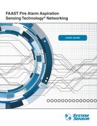
SpectrAlert <strong>Strobe</strong> C<strong>and</strong>ela Selections<br />
For strobe c<strong>and</strong>ela selection, adjust slide switch located on the<br />
rear of the product while watching the viewing window on the<br />
side of the reflector.<br />
Viewing Window<br />
A0133-00<br />
Permissible C<strong>and</strong>ela Settings<br />
C<strong>and</strong>ela Operating Voltage<br />
Setting<br />
12V 24V<br />
15 OK OK<br />
15/75 OK OK<br />
30 OK<br />
75 OK<br />
110 OK
SpectrAlert <strong>Horn</strong> Sound Measurements (dBA)<br />
SpectrAlert Ordering Information<br />
Model Description<br />
P1224MC <strong>Selectable</strong> <strong>Output</strong> <strong>Horn</strong>/<strong>Strobe</strong>, 12/24 volt, red<br />
P1224MCW <strong>Selectable</strong> <strong>Output</strong> <strong>Horn</strong>/<strong>Strobe</strong>, 12/24 volt, white<br />
P1224MCP <strong>Selectable</strong> <strong>Output</strong> <strong>Horn</strong>/<strong>Strobe</strong>, 12/24 volt, red,<br />
plain housing<br />
P1224MCPW <strong>Selectable</strong> <strong>Output</strong> <strong>Horn</strong>/<strong>Strobe</strong>, 12/24 volt,<br />
white, plain housing<br />
P1224MCK <strong>Selectable</strong> <strong>Output</strong> <strong>Horn</strong>/<strong>Strobe</strong>, 12/24 volt, red,<br />
outdoor<br />
P1224MCSP <strong>Selectable</strong> <strong>Output</strong> <strong>Horn</strong>/<strong>Strobe</strong>, 12/24 volt, red,<br />
“FUEGO” housing<br />
S1224MC <strong>Selectable</strong> <strong>Output</strong> <strong>Strobe</strong>, 12/24 volt, red<br />
S1224MCW <strong>Selectable</strong> <strong>Output</strong> <strong>Strobe</strong>, 12/24 volt, white<br />
S1224MCP <strong>Selectable</strong> <strong>Output</strong> <strong>Strobe</strong>, 12/24 volt, red, plain<br />
housing<br />
S1224MCPW <strong>Selectable</strong> <strong>Output</strong> <strong>Strobe</strong>, 12/24 volt, white,<br />
plain housing<br />
S1224MCK <strong>Selectable</strong> <strong>Output</strong> <strong>Strobe</strong>, 12/24 volt, red,<br />
outdoor<br />
S1224MCSP <strong>Selectable</strong> <strong>Output</strong> <strong>Strobe</strong>, 12/24 volt, red,<br />
“FUEGO” housing<br />
Notes<br />
<strong>Selectable</strong> <strong>Horn</strong> Tones 8-17.5V 16-33V<br />
Temporal Low<br />
Volume<br />
Non-<br />
Temporal<br />
DIP Switch Operation on P1224MC<br />
Factory<br />
OFF ON Default<br />
Low<br />
Temporal<br />
Electromech.<br />
High<br />
Volume<br />
Low<br />
Volume<br />
High<br />
Volume<br />
Model Description<br />
H12/24 <strong>Horn</strong>, 12/24 volt, red<br />
H12/24W <strong>Horn</strong>, 12/24 volt, white<br />
H12/24K <strong>Horn</strong>, 12/24 volt, red, outdoor<br />
Accessories<br />
MDL Sync•Circuit Module, red<br />
MDLW Sync•Circuit Module, white<br />
MDLWA Sync•Circuit Module, white, Canadian model<br />
S-MP Small Footprint Mounting Plate, red, for singlegang<br />
back box<br />
S-MPW Small Footprint Mounting Plate, white, for singlegang<br />
back box<br />
BBS Surface Mount Back Box Skirt, red<br />
BBSW Surface Mount Back Box Skirt, white<br />
D-MP Universal Mounting Plate (replacement), red<br />
D-MPW Universal Mounting Plate (replacement), white<br />
WBB Weatherproof Back Box<br />
All of these SpectrAlert products are designed for wall mount only. All outdoor models must use weatherproof back box model WBB. Installation of<br />
less than 75 c<strong>and</strong>ela strobes may be permissible under the equivalent facilitation clause of the ADAAG (Sec. 2.2). However, it is the responsibility of<br />
the person or entity designing the fire alarm system to determine the acceptability of less than 75 c<strong>and</strong>ela strobes. All 15/75 c<strong>and</strong>ela strobes or horn/<br />
strobes are recommended for 20′ × 20′ rooms or less.<br />
<strong>System</strong> <strong>Sensor</strong> Sales <strong>and</strong> Service<br />
<strong>System</strong> <strong>Sensor</strong> Headquarters<br />
3825 Ohio Avenue<br />
St. Charles, IL 60174<br />
Ph: 800/SENSOR2<br />
Fx: 630/377-6495<br />
www.systemsensor.com<br />
Electromechanical 67 75<br />
3000 Hz Interrupted 68 75<br />
Electromechanical 71 80<br />
3000 Hz Interrupted 72 81<br />
Electromechanical 71 79<br />
3000 Hz Interrupted 72 79<br />
Electromechanical 76 84<br />
3000 Hz Interrupted 77 86<br />
High<br />
Non-Temporal<br />
3000Hz<br />
<strong>System</strong> <strong>Sensor</strong> Canada<br />
Ph: 905.812.0767<br />
Fx: 905.812.0771<br />
<strong>System</strong> <strong>Sensor</strong> Europe<br />
Ph: 44.1403.276500<br />
Fx: 44.1403.276501<br />
DIP Switch<br />
Base (rear)<br />
A0110-00<br />
<strong>System</strong> <strong>Sensor</strong> in China<br />
Ph: 86.29.8832.0119<br />
Fx: 86.29.8832.5119<br />
<strong>System</strong> <strong>Sensor</strong> in Singapore<br />
Ph: 65.6273.2230<br />
Fx: 65.6273.2610<br />
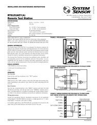
Typical weatherproof mounting with universal plate<br />
<strong>System</strong> <strong>Sensor</strong> – Far East<br />
Ph: 85.22.191.9003<br />
Fx: 85.22.736.6580<br />
<strong>System</strong> <strong>Sensor</strong> – Australia<br />
Ph: 613.54.281.142<br />
Fx: 613.54.281.172<br />
<strong>System</strong> <strong>Sensor</strong> – India<br />
Ph: 91.124.237.1770 x.2700<br />
Fx: 91.124.237.3118<br />
<strong>System</strong> <strong>Sensor</strong> – Russia<br />
Ph: 70.95.937.7982<br />
Fx: 70.95.937.7983<br />
© 2005 <strong>System</strong> <strong>Sensor</strong>. The company reserves the right to change product specifications without notice. A05-0325-006•9/05•#1526<br />
Gasket<br />
WBB<br />
Conduit<br />
Entrance<br />
Plate<br />
Slot<br />
Paper Liner<br />
For Plate<br />
Gasket<br />
#8-36 x 1/2˝ Flat Head<br />
Screw (4 total)<br />
Locking Rib<br />
A0135-02