Installation Instructions - System Sensor
Installation Instructions - System Sensor
Installation Instructions - System Sensor

Create successful ePaper yourself
Turn your PDF publications into a flip-book with our unique Google optimized e-Paper software.
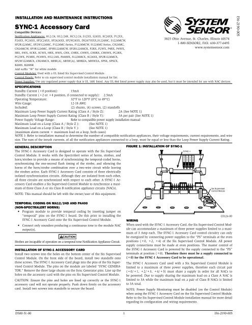
INSTALLATION AND MAINTENANCE INSTRUCTIONS<br />
SYNC-1 Accessory Card<br />
Compatible Devices:<br />
Notification Appliances: H12/24, H12/24K, HC12/24, S12XX, S24XX, SC24XX, P12XX,<br />
P24XX, PC24XX, SP2C24XX, SP2424XX, SP2W24XX, DS2475XXX,S1224MC, S1224MCW,<br />
SP2R1224MC, SP2W1224MC, P1224MC-Series, P1224MCW, S1224MC-Series, CH24MC,<br />
CH24MCW, SP3R1224MC, SP3R1224MCW, SP2R1224MCK, P2RX, P2WX, P4RX, P4WX,<br />
SRX, SWX, SCRX, SCWX, HRX, HWX, CHX, CHRX, CHWX, CHSRX, CHSWX, PC2RX,<br />
PC2WX, PC4RX, PC4WX, H12/24X, PA400X, S1224MCX, SC24XX, SP2R1224MCX,<br />
SP2W1224MCX, CH24MCX, MHR(A), MHW(A), MHRZA, MHWZA, SPSX, SPSCX,<br />
B200S, B200SR<br />
Add suffix “W” for white models<br />
Control Modules: Used with a UL listed Six Supervised Control Module.<br />
Control Panels: Refer to six supervised control module installation manual for list.<br />
3825 Ohio Avenue, St. Charles, Illinois 60174<br />
1-800-SENSOR2, FAX: 630-377-6495<br />
www.systemsensor.com<br />
Power Supplies: Use any regulated power supply that is UL 1481 listed. Any UL 864 listed power supply may also be used, but it must be intended for use with NAC devices.<br />
SpECIFICATIONS<br />
Standby Current (+0 position): 15mA<br />
Standby Current (+2 or +4 position, if connected to supply): 2.5mA<br />
Operating Temperature: 32ºF to 120ºF (0ºC to 49ºC)<br />
Wire Gauge: 12-18 AWG<br />
Included: (2) shunts, (4) screws, (2) standoffs<br />
Maximum Loop Power Supply Current Rating (Class A / Style Z): 2A (See NOTE 1)<br />
Maximum Loop Power Supply Current Rating (Class B / Style Y): 3A per pair (See NOTE 1)<br />
Power Supply Voltage Range: Refer to compatible power supply installation manual<br />
Maximum Load on a Loop (Class A / Style Z ): (See NOTE 1)<br />
Maximum Load on a Loop (Class B / Style Y ): (See NOTE 1)<br />
(maximum alarm current = maximum load on a loop, both cases)<br />
NOTE 1: Refer to installation manual to determine the number of compatible notification appliances, their voltage requirements, current requirements, and wire<br />
size. The sum of the inrush currents, of all the notification appliances connected to a loop, must be equal or less than the Loop Power Supply Current Rating.<br />
gENERAL DESCRIpTION<br />
The SYNC-1 Accessory Card is designed to operate with the Six Supervised<br />
Control Module. It works with the SpectrAlert series of horns, strobes, and<br />
horn/strobes to provide a means of synchronizing the temporal-coded horns,<br />
synchronizing the one-second flash timing of the strobe, and silencing the<br />
horns of the horn/strobe combination over a two-wire circuit while leaving<br />
the strobes active. Each SYNC-1 Accessory Card consists of three electrically<br />
isolated synchronization circuits. Although they are isolated from each other,<br />
all three circuits are synchronized with respect to each other. A SYNC-1 Accessory<br />
Card enables a Six Supervised Control Module to synchronize a maximum<br />
of three Class A or six Class B notification appliance circuits (NACs).<br />
NOTE: This manual should be left with the owner/user of this equipment.<br />
TEMpORAL CODINg ON MA12/24D AND pA400<br />
(NON-SpECTRALERT HORNS)<br />
• Program module to provide temporal coding by inserting jumper on<br />
“temporal” pins on the SYNC-1 board. Do this prior to installing the<br />
SYNC-1 Accessory Card onto the Six Supervised Control Module.<br />
• Connect only sounders producing a continuous tone to the module NAC<br />
output(s).<br />
CAUTION<br />
Strobes are incapable of operation on a temporal tone Notification Appliance Circuit.<br />
INSTALLATION OF SYNC-1 ACCESSORY CARD<br />
Install two screws into the holes on the bottom center of the Six Supervised<br />
Control Module. On the front side of the board, install two standoffs onto<br />
these screws. The SYNC-1 Accessory Card plugs into the pins of the Six Supervised<br />
Control Module. The pins on the module are labeled “SYNC GENERA-<br />
TOR.” Remove the three large shunts on the Sync Generator pins. Line up the<br />
holes on the accessory card with the pins on Six Supervised Control Module.<br />
CAUTION: Ensure the pins and holes are lined up correctly or the SYNC-1<br />
accessory card will not operate properly. Push down firmly on the accessory<br />
card. Install two screws into standoffs to secure the board.<br />
FIgURE 1: INSTALLATION OF SYNC-1<br />
Six Supervised<br />
Control Module<br />
D500-51-00 1 I56-2190-005<br />
SYNC-1<br />
C0126-00<br />
WIRINg<br />
When used with the SYNC-1 Accessory Card, the Six Supervised Control Module<br />
can accommodate a maximum of three power supplies limited to a maximum<br />
of 3 Amp each. The SYNC-1 Accessory Card control circuitry can only<br />
be energized by connecting power supplies to the “PS” terminals at the even<br />
positions (+0, +2, +4) of the Six Supervised Control Module. All power<br />
supply connections must be made at even positions. The master control of<br />
the SYNC-1 Accessory Card is powered by the supply connected to the “PS”<br />
terminals at position (+0). Therefore there must be a supply connected to<br />
(+0) for the SYNC-1 Accessory Card to be operational.<br />
The SYNC-1 Accessory Card used with a Six Supervised Control Module is<br />
limited to a maximum of three power supplies, therefore each circuit pair<br />
(+0/+1, +2/+3, +4/+5) must share a supply in order for all NACs to<br />
be powered. Due to supply sharing the maximum load on a Class A NAC is<br />
limited to 3A while the maximum load on a pair of Class B NACs is limited<br />
to 3A total.<br />
NOTE: Power Supply Monitoring must be disabled (on the Control Module)<br />
when using the SYNC-1 Accessory Card on the Six Supervised Control Module.<br />
Refer to the Six Supervised Control Module installation manual for more detail<br />
regarding its configuration and wiring requirements.<br />
TEMPORAL<br />
UNUSED<br />
UNUSED<br />
UNUSED<br />
I56-2190-005
FIgURE 2: CONNECTINg TWO SYNC-1 CARDS (CLASS B OpERATION, ONE pOWER SUppLY USED)<br />
T0<br />
+0<br />
+ — — + + — — + + — — + + — — + + — — +<br />
NAC PS NAC PS NAC PS NAC PS NAC PS<br />
TOP – + – + SLC<br />
BOT + NAC – – PS +<br />
T1<br />
+1<br />
T2<br />
+2<br />
T3<br />
+3<br />
T4<br />
+4<br />
T5<br />
+5<br />
T10<br />
T11 T12 T13 T14 T15<br />
— +<br />
SLAVE IN<br />
To interconnect SYNC-1 Accessory Cards wire the Slave and Horn connections<br />
as shown in Figure 2. The slave wires will synchronize all NACs corresponding<br />
to the interconnected boards. Any SYNC-1 which has no connections to its<br />
slave in terminals will operate as a master. It will generate a signal which will<br />
be duplicated by all interconnected units downstream. The horn wires will enable<br />
horn control on all NACs corresponding to the interconnected boards.<br />
Horn control also requires a silenceable NAC circuits to be wired to the horn<br />
in terminals of the master SYNC-1 Accessory Card as shown in Figure 3.<br />
A maximum of 11 Slaves Sync-1 Cards can be connected to a Master Sync-1<br />
Card, totalling 12.<br />
CAUTION<br />
All horn and slave wiring interconnecting SYNC-1 accessory cards must be<br />
contained within the same enclosure. If multiple enclosures are used they<br />
must be located within 20 feet of each other with all horn and slave wiring between<br />
enclosures routed inside of conduit. This conduit should be grounded<br />
metal containing no other field wiring.<br />
FIgURE 3: HORN OpERATION<br />
HORN IN — +<br />
A/B SELECT<br />
DISABLE 1<br />
DISABLE 2<br />
DISABLE 3<br />
Silenceable NAC Output<br />
Wiring is<br />
Power Limited<br />
ENABLE POWER SUPPLY MONITOR<br />
ENABLE POWER SUPPLY MONITOR<br />
DISABLE SHORT CIRCUIT PROTECTION<br />
— +<br />
— + — +<br />
SLAVE OUT HORN OUT<br />
HORN IN — +<br />
SLAVE IN<br />
3<br />
2<br />
1 0<br />
3<br />
2<br />
1 0<br />
T16<br />
BASE ADDRESS<br />
4 5 6 7 8 9<br />
4 5 6 7 8 9<br />
Wiring is<br />
Power Limited<br />
T0<br />
+0<br />
+ — — + + — — + + — — + + — — + + — — +<br />
NAC PS NAC PS NAC PS NAC PS NAC PS<br />
TOP – + – + SLC<br />
BOT + NAC – – PS +<br />
T1<br />
+1<br />
T2<br />
+2<br />
T3<br />
+3<br />
T4<br />
+4<br />
T5<br />
+5<br />
T11 T12 T13 T14 T15<br />
T10<br />
— +<br />
— + — +<br />
SLAVE OUT HORN OUT<br />
HORN IN — +<br />
SLAVE IN<br />
A/B SELECT<br />
DISABLE 1<br />
DISABLE 2<br />
DISABLE 3<br />
ENABLE POWER SUPPLY MONITOR<br />
ENABLE POWER SUPPLY MONITOR<br />
DISABLE SHORT CIRCUIT PROTECTION<br />
— + — +<br />
SLAVE OUT HORN OUT<br />
3<br />
2<br />
1 0<br />
3<br />
2<br />
1 0<br />
To Next SYNC-1 Horn In<br />
T16<br />
BASE ADDRESS<br />
4 5 6 7 8 9<br />
4 5 6 7 8 9<br />
C0123-01<br />
C0122-01<br />
D500-51-00 2 I56-2190-005
The sounder and/or strobe will not work without power. The sounder/strobe gets its<br />
power from the fire/security panel monitoring the alarm system. If power is cut off for<br />
any reason, the sounder/strobe will not provide the desired audio or visual warning.<br />
The sounder may not be heard. The loudness of the sounder meets (or exceeds) current<br />
Underwriters Laboratories’ standards. However, the sounder may not alert a sound<br />
sleeper or one who has recently used drugs or has been drinking alcoholic beverages. The<br />
sounder may not be heard if it is placed on a different floor from the person in hazard or<br />
if placed too far away to be heard over the ambient noise such as traffic, air conditioners,<br />
machinery or music appliances that may prevent alert persons from hearing the alarm.<br />
The sounder may not be heard by persons who are hearing impaired.<br />
NOTE: Strobes must be powered continuously for sounder operation.<br />
<strong>System</strong> <strong>Sensor</strong> warrants its enclosed product to be free from defects in materials and<br />
workmanship under normal use and service for a period of three years from date of<br />
manufacture. <strong>System</strong> <strong>Sensor</strong> makes no other express warranty for the enclosed product.<br />
No agent, representative, dealer, or employee of the Company has the authority to increase<br />
or alter the obligations or limitations of this Warranty. The Company’s obligation<br />
of this Warranty shall be limited to the replacement of any part of the product which<br />
is found to be defective in materials or workmanship under normal use and service<br />
during the three year period commencing with the date of manufacture. After phoning<br />
<strong>System</strong> <strong>Sensor</strong>’s toll free number 800-SENSOR2 (736-7672) for a Return Authorization<br />
number, send defective units postage prepaid to: <strong>System</strong> <strong>Sensor</strong>, Returns Department, RA<br />
WARNING<br />
THE LIMITATIONS OF SOUNDER/STROBES<br />
THREE-YEAR LIMITED WARRANTY<br />
The signal strobe may not be seen. The electronic visual warning signal uses an extremely<br />
reliable xenon flash tube. It flashes at least once every second. The strobe must<br />
not be installed in direct sunlight or areas of high light intensity (over 60 foot candles)<br />
where the visual flash might be disregarded or not seen. The strobe may not be seen by<br />
the visually impaired.<br />
The signal strobe may cause seizures. Individuals who have positive photoic response<br />
to visual stimuli with seizures, such as persons with epilepsy, should avoid prolonged<br />
exposure to environments in which strobe signals, including this strobe, are activated.<br />
The signal strobe cannot operate from coded power supplies. Coded power supplies<br />
produce interrupted power. The strobe must have an uninterrupted source of power in<br />
order to operate correctly. <strong>System</strong> <strong>Sensor</strong> recommends that the horn and signal strobe<br />
always be used in combination so that the risks from any of the above limitations are<br />
minimized.<br />
#__________, 3825 Ohio Avenue, St. Charles, IL 60174. Please include a note describing<br />
the malfunction and suspected cause of failure. The Company shall not be obligated to<br />
replace units which are found to be defective because of damage, unreasonable use,<br />
modifications, or alterations occurring after the date of manufacture. In no case shall the<br />
Company be liable for any consequential or incidental damages for breach of this or any<br />
other Warranty, expressed or implied whatsoever, even if the loss or damage is caused by<br />
the Company’s negligence or fault. Some states do not allow the exclusion or limitation of<br />
incidental or consequential damages, so the above limitation or exclusion may not apply<br />
to you. This Warranty gives you specific legal rights, and you may also have other rights<br />
which vary from state to state.<br />
D500-51-00 3 I56-2190-005
D500-51-00 4 I56-2190-005<br />
©2009 <strong>System</strong> <strong>Sensor</strong>