KLINGER Spiral Wound Gaskets - Klinger Danmark A/S
KLINGER Spiral Wound Gaskets - Klinger Danmark A/S
KLINGER Spiral Wound Gaskets - Klinger Danmark A/S

You also want an ePaper? Increase the reach of your titles
YUMPU automatically turns print PDFs into web optimized ePapers that Google loves.
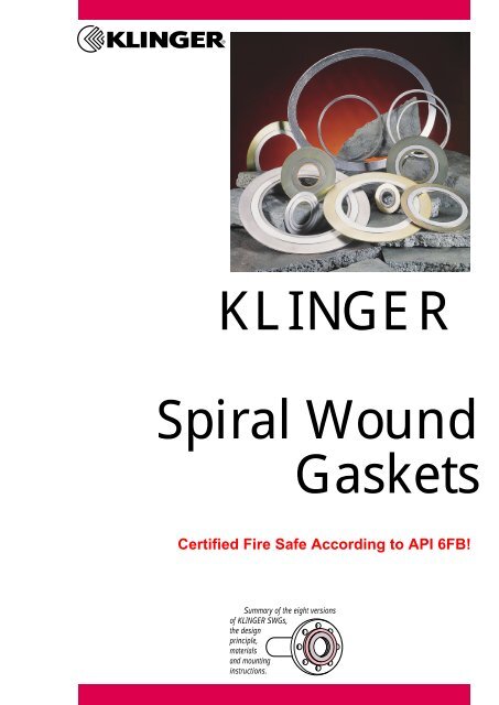
<strong>KLINGER</strong><br />
<strong>Spiral</strong> <strong>Wound</strong><br />
<strong>Gaskets</strong><br />
Certified Fire Safe According to API 6FB!<br />
Summary of the eight versions<br />
of <strong>KLINGER</strong> SWGs,<br />
the design<br />
principle,<br />
materials<br />
and mounting<br />
instructions.
Type R<br />
Wide choice of materials for metal<br />
strip and filler.<br />
Suitable for high pressures and<br />
temperatures.<br />
Recommended for flanges with<br />
tongue and groove.<br />
Type CR<br />
Solid metal outer ring used as a<br />
centerring device and compression<br />
stop.<br />
Used on raised face and flat face<br />
flanges.<br />
Standard Metal strip materials Gasket thicknesses<br />
1.4301<br />
1.4401<br />
1.4404<br />
1.4541<br />
1.4571<br />
Special version:<br />
Monel 400 ® , InConel 600 ® , InConel 625 ® , InConel X750 ® ,<br />
Nickel 200 ® , Titanium, Incoloy 800 ® , Incoloy 825 ®<br />
304<br />
316<br />
316 L<br />
321<br />
316 Ti<br />
Other materials on request<br />
The design principle of the<br />
<strong>KLINGER</strong> <strong>Spiral</strong>-<strong>Wound</strong><br />
<strong>Gaskets</strong><br />
The basic element of every gasket is<br />
the wound core. The V-shaped metal<br />
strip is spirally wound with the softmaterial<br />
filler.<br />
<strong>KLINGER</strong><br />
<strong>Spiral</strong>-<strong>Wound</strong> <strong>Gaskets</strong><br />
Nominal<br />
thickness<br />
3.2 mm<br />
4.5 mm<br />
7.2 mm<br />
To improve the mechanical<br />
strength and other sealing characteristics,<br />
some layers at the beginning<br />
and at the end are wound without soft<br />
material and spot-welded over the<br />
total circumference.<br />
The constant tensile force during<br />
the complete winding process permits<br />
a defined, constant thickness of the<br />
structure.<br />
Type RIR<br />
Solid metal inner ring.<br />
Use with high pressures and<br />
temperatures.<br />
Male to female flanges.<br />
Compressed Guide ring<br />
thickness thickness<br />
2.3 - 2.5 mm 2 - 2.2 mm<br />
3.2 - 3.4 mm 3 - 3.3 mm<br />
5.0 - 5.5 mm 5 - 5.5 mm<br />
This gives the gasket recovery<br />
forces which provide for a reliable<br />
surface load even at fluctuating operating<br />
conditions.<br />
In the present 8 versions, the<br />
basic element is added by inner<br />
and/or outer rings as needed.
Type CRIR Type CRIR/<br />
PTFE inner ring<br />
Solid metal outer and inner rings.<br />
For use at high pressures and<br />
temperatures.<br />
Suitable for raised face or flat face<br />
flanges.<br />
Prevents turbulences and protects<br />
the flanges from erosion.<br />
Protects the inner windings of the<br />
gasket element from high<br />
temperatures.<br />
Standard materials outer ring<br />
Carbon steel,<br />
colour-powder coated<br />
Stainless steel<br />
acc. to the standard metal strip<br />
materials<br />
<strong>KLINGER</strong><br />
<strong>Spiral</strong>-<strong>Wound</strong> <strong>Gaskets</strong><br />
Solid metal outer ring, PTFE inner<br />
ring.<br />
Suitable for raised face or flat face<br />
flanges.<br />
PTFE inner ring acts as an additional<br />
gasket and protects the inner windings<br />
of the gasket element from the fluid.<br />
Standard materials inner ring<br />
Stainless steel<br />
acc. to the standard metal strip<br />
materials<br />
Type CRIR/<br />
<strong>KLINGER</strong>graphite inner ring<br />
Solid metal inner ring with <strong>KLINGER</strong>graphite<br />
facing.<br />
For use at high pressures and<br />
temperatures.<br />
Suitable for raised face or flat face<br />
flanges.<br />
Suitable for corrosive media.<br />
Graphite inner ring acts as an<br />
additional gasket.<br />
Fillers and temperature limits<br />
Ceramics<br />
approx. 800°C<br />
<strong>KLINGER</strong>graphite* approx. 500°C<br />
PTFE<br />
approx. 260°C<br />
Mica<br />
approx. 900°C<br />
*pure graphite standard 98% purity<br />
or 99.85% nuclear grade
Type RHD<br />
<strong>Spiral</strong> wound sealing element.<br />
<strong>Wound</strong> high density.<br />
Wide choice of materials for metal<br />
strip and filler material.<br />
For use in high-pressure pumps,<br />
high-pressure valves and gas<br />
applications.<br />
Low emission tested.<br />
Recommended<br />
sealing strip roughness<br />
These gaskets are capable of giving<br />
an excellent seal over a wide range of<br />
flange surface finishes.<br />
<strong>KLINGER</strong><br />
<strong>Spiral</strong>-<strong>Wound</strong> <strong>Gaskets</strong><br />
Type R with<br />
<strong>KLINGER</strong>graphite facing<br />
<strong>KLINGER</strong>graphite facing 0.5 mm.<br />
For use in manhole gaskets.<br />
Suitable for use with low bolt loads<br />
and uneven gasket surfaces.<br />
Double sealing effect.<br />
However, as a general guide we<br />
recommend the following:<br />
Type HTX for<br />
heat<br />
exchangers<br />
Combined inner and outer rings.<br />
The inner ring could have pass bars<br />
or could carry either a metal clad or<br />
soft gasket with pass bars.<br />
general<br />
critical<br />
vacuum<br />
R a micrometer<br />
3.2 – 5.1<br />
3.2<br />
2.0<br />
(Larger flange surface finishes require<br />
higher bolt loads)<br />
Subject to technical alterations.<br />
Status: April 1999
Mounting Instructions<br />
The principle<br />
The spiral wound function is<br />
based on the metal winding/ filler relationship<br />
and the flange surfaces.<br />
The surface roughness should be<br />
approx. R a 3.2 µm. These gaskets<br />
can be used in flanges with larger<br />
surface roughnesses, but in this<br />
case the bolt loads should be<br />
increased so as to ensure proper<br />
function of the gasket.<br />
When the gasket is<br />
compressed during mounting,<br />
the homogeneous filler „flows“ into<br />
the irregularities of the flange. The<br />
metal windings enclose the filler and,<br />
at the same time, ensure the strength<br />
and elasticity of the gasket.<br />
If the gasket is equipped with a<br />
PTFE filler it must have an inner ring<br />
since the PTFE permits no further<br />
compression, as is the case with other<br />
fillers. On the one hand, it prevents<br />
the gasket from springing open and<br />
on the other, penetration of the flowing<br />
PTFE in the pipeline. The larger<br />
the surface roughnesses in the flange<br />
surface, the larger the surface load<br />
required to permit a flow of the PTFE<br />
in the irregularities.<br />
Mounting<br />
Flange surface condition:<br />
1. metallically clean<br />
2. plane-parallel<br />
3. dry<br />
4. fat free<br />
Do not use separating agents<br />
or sealing aids!<br />
Mounting<br />
The bolts should be free of damage<br />
and lubricated with high-temperature<br />
resistant greases before mounting.<br />
Insert the gasket and fasten bolts<br />
finger-tight.<br />
Next, tighten the bolts crosswise<br />
(see sketch) in at least 3 to 4 passes.<br />
The more passes you perform, the<br />
more uniform the force which is introduced<br />
into the flange-gasket system.<br />
In the last pass, the bolts must be<br />
tightened only clockwise.<br />
4<br />
1<br />
7 5<br />
6<br />
2<br />
All information is provided in<br />
accordance with the current state of<br />
knowledge. As we cannot influence the<br />
specific application conditions, we<br />
would ask you to consider this as a<br />
non-binding recommendation.<br />
We can assume no liability for any<br />
resulting damage.<br />
<strong>KLINGER</strong> reserve the right to<br />
technical modifications.<br />
8<br />
3
DN<br />
d1 10 –<br />
320<br />
d2 10 –<br />
320<br />
Subject to technical alterations.<br />
Status: April 1999<br />
Certified according to<br />
DIN EN ISO 9001.<br />
d3 PN10 – PN 64 –<br />
40 320<br />
<strong>KLINGER</strong> SWG<br />
types CR/CRIR<br />
Suitable for flanges in accordance with DIN and BS 4504,<br />
measures in mm<br />
d4 10 16 25 40 64<br />
CR CRIR<br />
d 2<br />
d 3<br />
d 4<br />
100 160 250<br />
d1 d2 d3 d4
Nominal width<br />
d3 d2 d4 øA of<br />
sealing elem.<br />
øI of sealing element<br />
øA of centering ring<br />
Press. st. [lbs]<br />
Pressure stage [lbs] Pressure stage [lbs]<br />
150 300 400 600 900 1,500 2,500 150 300 400 600 900 1,500 2,500<br />
150<br />
300<br />
400<br />
600<br />
900<br />
1,500<br />
2,500<br />
Subject to technical alterations.<br />
Status: October 2000<br />
Certified according to<br />
DIN EN ISO 9001.<br />
<strong>KLINGER</strong> SWG<br />
types CR/CRIR<br />
<strong>Gaskets</strong> in accordance with ASME B 16.20,<br />
flanges according ANSI B 16.5, measures in inch<br />
CR CRIR<br />
d 2<br />
d 3<br />
d 4<br />
d1 d2 d3 d4
Nominal width<br />
150<br />
300<br />
400<br />
600<br />
900<br />
1,500<br />
2,500<br />
Subject to technical alterations.<br />
Status: October 2000<br />
Certified according to<br />
DIN EN ISO 9001.<br />
<strong>KLINGER</strong> SWG<br />
types CR/CRIR<br />
<strong>Gaskets</strong> in accordance with ASME B 16.20,<br />
flanges according ANSI B 16.5, measures in mm<br />
d3 d2 d4 øA of<br />
sealing elem.<br />
øI of sealing element<br />
øA of centering ring<br />
Press. st. [lbs]<br />
Pressure stage [lbs] Pressure stage [lbs]<br />
150 300 400 600 900 1,500 2,500 150 300 400 600 900 1,500 2,500<br />
CR CRIR<br />
d 2<br />
d 3<br />
d 4<br />
d1 d2 d3 d4
Nominal<br />
width<br />
d 1<br />
Pressure stage [lbs]<br />
150 300 400 600 900 1500 2500<br />
Subject to technical alterations.<br />
Status: October 2000<br />
Certified according to<br />
DIN EN ISO 9001.<br />
<strong>KLINGER</strong> SWG<br />
Inner ring dimension<br />
<strong>Gaskets</strong> according ASME B 16.20, flanges according ANSI B 16.5,<br />
measures in inch/mm<br />
CRIR<br />
3 13 /128<br />
3 109 /128<br />
4 115 /128<br />
5 51 /64<br />
7 3 /4<br />
9 11 /16<br />
78.7<br />
97.8<br />
124.5<br />
147.3<br />
196.9<br />
246.1<br />
d1 d2 d3 d4
Nominal width<br />
d1 d2 d3 d4 d1 d2 d3 d4 d1 d2 d3 d4 d1 d2 d3 d4 Pressure stage [lbs] Pressure stage [lbs] Pressure stage [lbs] Pressure stage [lbs]<br />
Inner<br />
ring<br />
150<br />
Sealing<br />
element<br />
Centering<br />
ring<br />
ø I ø I ø A ø A<br />
Subject to technical alterations.<br />
Status: 1995<br />
Certified according to<br />
DIN EN ISO 9001.<br />
Inner<br />
ring<br />
300<br />
Sealing<br />
element<br />
Centering<br />
ring<br />
ø I ø I ø A ø A<br />
Inner<br />
ring<br />
<strong>KLINGER</strong> SWG<br />
types CR/CRIR<br />
Large flanges in accordance with API 605, measures in inch<br />
600<br />
Sealing<br />
element<br />
Centering<br />
ring<br />
ø I ø I ø A ø A<br />
CR CRIR<br />
d 2<br />
d 3<br />
d 4<br />
Inner<br />
ring<br />
900<br />
Sealing<br />
element<br />
Centering<br />
ring<br />
ø I ø I ø A ø A<br />
d1 d2 d3 d4
Nominal width<br />
Inner<br />
ring<br />
Subject to technical alterations.<br />
Status: 1995<br />
Certified according to<br />
DIN EN ISO 9001.<br />
<strong>KLINGER</strong> SWG<br />
types CR/CRIR<br />
Large flanges in accordance with MSS SP 44, measures in inch<br />
d1 d2 d3 d4 d1 d2 d3 d4 d1 d2 d3 d4 d1 d2 d3 d4 Pressure stage [lbs] Pressure stage [lbs] Pressure stage [lbs] Pressure stage [lbs]<br />
150<br />
Sealing<br />
element<br />
Centering<br />
ring<br />
ø I ø I ø A ø A<br />
Inner<br />
ring<br />
300<br />
Sealing<br />
element<br />
Centering<br />
ring<br />
ø I ø I ø A ø A<br />
Inner<br />
ring<br />
600<br />
Sealing<br />
element<br />
Centering<br />
ring<br />
ø I ø I ø A ø A<br />
CR CRIR<br />
d 2<br />
d 3<br />
d 4<br />
Inner<br />
ring<br />
900<br />
Sealing<br />
element<br />
Centering<br />
ring<br />
ø I ø I ø A ø A<br />
d1 d2 d3 d4
Nominal width<br />
d 1 d 2 d 3 d 4 d 2 d 3<br />
Inner<br />
ring<br />
Sealing<br />
element<br />
o/ I o/ I o/ A o/ A o/ A o/ I o/ A<br />
Subject to technical alterations.<br />
Status: October 2000<br />
Certified according to<br />
DIN EN ISO 9001.<br />
Centering<br />
ring<br />
Sealing<br />
element<br />
d 4 d 2 d 3 d 4 d 2 d 3<br />
Centering<br />
ring<br />
<strong>KLINGER</strong> SWG<br />
types CR/CRIR<br />
Flanges in accordance with BS10, measures in inch<br />
Sealing<br />
element<br />
Centering<br />
ring<br />
Sealing<br />
element<br />
d 4<br />
Centering<br />
ring<br />
o/ A o/ I o/ A o/ A o/ I o/ A o/ A<br />
CR CRIR<br />
d 2<br />
d 3<br />
d 4<br />
d1 d2 d3 d4
Nominal width<br />
[inch]<br />
d1 d2 d3 d4 d2 d3 d4 d2 d3 d4 Pressure stage [lbs] P. s. [lbs]<br />
Pressure stage [lbs]<br />
Pressure stage [lbs]<br />
150 300 bis 1500 300 400 600 900 1500 2500<br />
Inner Sealing Cente- Sealing<br />
Centering ring Sealing Cente-<br />
ring element ring element<br />
element ring<br />
ring<br />
ring<br />
o/ I o/ I o/ A o/ A o/ I o/ A o/ A o/ I o/ A o/ A<br />
Subject to technical alterations.<br />
Status: 1995<br />
Certified according to<br />
DIN EN ISO 9001.<br />
<strong>KLINGER</strong> SWG<br />
types CR/CRIR<br />
Flanges in accordance with BS 3381, ANSI B 16.5,<br />
measures in inch<br />
CR CRIR<br />
d 2<br />
d 3<br />
d 4<br />
d1 d2 d3 d4
Nominal width<br />
[inch]<br />
d1 d2 d3 d4 d2 d3 d4 d2 d3 d4 Pressure stage [lbs] P. s. [lbs]<br />
Pressure stage [lbs]<br />
Pressure stage [lbs]<br />
150 300 bis 1500 300 400 600 900 1500 2500<br />
Inner Sealing Cente- Sealing<br />
Centering ring Sealing Cente-<br />
ring element ring element<br />
element ring<br />
ring<br />
ring<br />
o/ I o/ I o/ A o/ A o/ I o/ A o/ A o/ I o/ A o/ A<br />
Subject to technical alterations.<br />
Status: 1995<br />
Certified according to<br />
DIN EN ISO 9001.<br />
<strong>KLINGER</strong> SWG<br />
types CR/CRIR<br />
Flanges in accordance with BS 3381, ANSI B 16.5,<br />
measures in mm<br />
CR CRIR<br />
d 2<br />
d 3<br />
d 4<br />
d1 d2 d3 d4
Nominal width<br />
Nominal width<br />
d 2<br />
d 3<br />
[mm] [inch] o/ I o/ A<br />
d 4<br />
Pressure stage [lbs]<br />
150 300 600<br />
900<br />
Sealing Cente- Sealing Cente- Sealing Cente- Sealing<br />
element ring element ring element ring element<br />
ring<br />
ring<br />
ring<br />
o/ A<br />
Subject to technical alterations.<br />
Status: 1995<br />
Certified according to<br />
DIN EN ISO 9001.<br />
d 2<br />
o/ I<br />
d 3<br />
o/ A<br />
d 4<br />
o/ A<br />
d 2<br />
o/ I<br />
d 3<br />
o/ A<br />
d 4<br />
o/ A<br />
<strong>KLINGER</strong> SWG<br />
types CR/CRIR<br />
In accordance with the french standard NF–M–87621,<br />
measures in mm<br />
d 2<br />
o/ I<br />
d 3<br />
o/ A<br />
d 4<br />
Centering<br />
ring<br />
o/ A<br />
d 2<br />
1500<br />
Sealing<br />
element<br />
CR CRIR<br />
o/ I<br />
d 2<br />
d 3<br />
d 4<br />
d 3<br />
o/ A<br />
d 4<br />
Centering<br />
ring<br />
o/ A<br />
d 2<br />
2500<br />
Sealing<br />
element<br />
o/ I<br />
d 3<br />
o/ A<br />
d 4<br />
Centering<br />
ring<br />
o/ A<br />
d1 d2 d3 d4
Nominal<br />
width<br />
d1 d2 d3 d4 d1 d2 d3 d4 Nominal pressure 10 k<br />
Nominal pressure 16 k to 20 k<br />
Inner- Sealing Centering<br />
Inner- Sealing Centering<br />
ring<br />
element<br />
ring<br />
ring<br />
element<br />
ring<br />
o/ I o/ I o/ A o/ A<br />
o/ I o/ I o/ A o/ A<br />
Subject to technical alterations.<br />
Status: October 2000<br />
Certified according to<br />
DIN EN ISO 9001.<br />
Nominal<br />
width<br />
<strong>KLINGER</strong> SWG<br />
types CR/CRIR<br />
Fitting to JIS flanges.<br />
Nominal pressure 10 k and 16 to 20 k, measures in mm<br />
CR CRIR<br />
d 2<br />
d 3<br />
d 4<br />
d1 d2 d3 d4