Service Manual - Fontaine International
Service Manual - Fontaine International
Service Manual - Fontaine International

You also want an ePaper? Increase the reach of your titles
YUMPU automatically turns print PDFs into web optimized ePapers that Google loves.
Assembly<br />
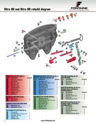
Refer to exploded view of assembly on page 18 to identify item number and parts.<br />
Adequate lubrication should be used<br />
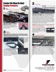
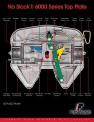
1. Insert rotating locking jaw<br />
Insert the rotating jaw (item 28) after applying a light<br />
coating of grease. Note: Insert the jaw so that the hole in<br />
the cover plate lines up with the hole in the rotating jaw.<br />
Raise the fifth wheel and then insert the long pivot pin<br />
(item 7) into the fifth wheel and then into the rotating jaw.<br />
Note: Make sure the notched portion of the pivot pin is<br />
inserted into the fifth wheel first. Secure the pivot pin in<br />
place with a new pivot pin clip (item 29).<br />
Rotating locking jaw (28) 28<br />
7<br />
29<br />
Pivot pin clip (29)<br />
and pivot pin (7)<br />
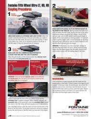
3. Insert wedge, and handle<br />
Insert the new short pivot pin (item 20) into the locking<br />
wedge (item 30) after applying a light coat of grease. Insert<br />
the locking wedge into the wheel. Move the locking wedge<br />
in behind the rotating locking jaw (item 28) to verify operation.<br />
Now slide the locking wedge back toward the outside<br />
of the wheel. This will assist in installing the operating<br />
handle. Insert the end of the operating handle (item 31) into<br />
the slot at the bottom of the fifth wheel and over the locking<br />
wedge pivot pin. Rotate the operating handle towards the<br />
center of the fifth wheel. This will slide the locking wedge<br />
behind the locking jaw.<br />
Before rebuilding the assembly, check to make sure<br />
that there are no cracks in the crossmembers or other<br />
components. Also check bracket pin holes to ensure<br />
they are not overly worn (pins should fit snugly). Refer<br />
to exploded view of assembly on page 18 to identify<br />
item numbers and parts.<br />
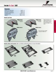
2. Insert the pull handle and<br />
secondary lock<br />
Insert the pull handle. After<br />
applying a light coat of grease<br />
to the pivot points, insert the<br />
secondary lock latch (item 21)<br />
into the fifth wheel. Attach the<br />
pull handle to the secondary lock<br />
latch using the 1/2” hex head bolt,<br />
spacer bushing, washer and new<br />
lock nut (items 15, 16, 17 & 22).<br />
Pivot pin<br />
(20)<br />
Rotating locking jaw (28)<br />
20<br />
Locking<br />
wedge (30)<br />
FONTAINE<br />
FIFTH WHEEL ®<br />
Pull handle (18)<br />
Secondary<br />
lock (21)<br />
Operating<br />
handle (31)<br />
800-874-9780 • www.fifthwheel.com 21<br />
15<br />
17<br />
16<br />
22