Kamatics Fiberlon™ Bearings - Kaman Corporation
Kamatics Fiberlon™ Bearings - Kaman Corporation
Kamatics Fiberlon™ Bearings - Kaman Corporation

You also want an ePaper? Increase the reach of your titles
YUMPU automatically turns print PDFs into web optimized ePapers that Google loves.
Spherical <strong>Bearings</strong><br />
<strong>Kamatics</strong> <strong>Corporation</strong> has designed and<br />
manufactured self-lubricated spherical<br />
bearings since 1966. The original <strong>Kamatics</strong><br />
spherical bearing was made from compacted<br />
carbon matrix liners operating against a<br />
chrome oxide coated and polished surface.<br />
This was known as a “KAcarb” bearing and<br />
is still in use today for applications operating<br />
at temperatures up to 1200°F degrees F<br />
(635°C). Since the early 1970’s <strong>Kamatics</strong><br />
has manufactured spherical bearings with<br />
KAron self-lube liners for temperatures to<br />
400°F (204°C) and KAtherm for<br />
temperatures to 600°F (315°C). Contact<br />
your <strong>Kamatics</strong> representative for further<br />
information for KAtherm and KAcarb<br />
applications.<br />
Spherical Bearing Design:<br />
The design criterion for a KAron lined<br />
spherical bearing is similar to the criteria for<br />
a journal bearing. The major difference is<br />
that the inner race is supplied within the<br />
bearing assembly and its hardness, surface<br />
finish and corrosion resistance is normally<br />
left up to the bearing manufacturer.<br />
Equation 1 provides a method for<br />
calculating bearing pressures for spherical<br />
bearings and is similar to the journal bearing<br />
“projected area” approach.<br />
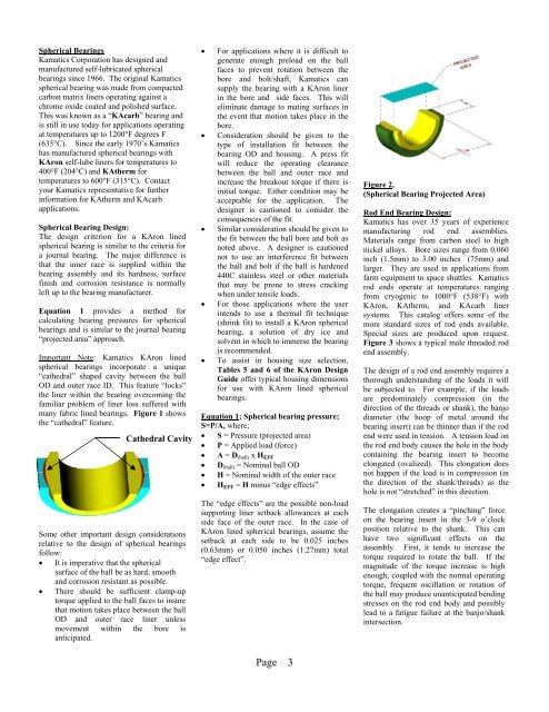
Important Note: <strong>Kamatics</strong> KAron lined<br />
spherical bearings incorporate a unique<br />
“cathedral” shaped cavity between the ball<br />
OD and outer race ID. This feature “locks”<br />
the liner within the bearing overcoming the<br />
familiar problem of liner loss suffered with<br />
many fabric lined bearings. Figure 1 shows<br />
the “cathedral” feature.<br />
Figure 1<br />
Cathedral Cavity<br />
Some other important design considerations<br />
relative to the design of spherical bearings<br />
follow:<br />
It is imperative that the spherical<br />
surface of the ball be as hard, smooth<br />
and corrosion resistant as possible.<br />
There should be sufficient clamp-up<br />
torque applied to the ball faces to insure<br />
that motion takes place between the ball<br />
OD and outer race liner unless<br />
movement within the bore is<br />
anticipated.<br />
For applications where it is difficult to<br />
generate enough preload on the ball<br />
faces to prevent rotation between the<br />
bore and bolt/shaft, <strong>Kamatics</strong> can<br />
supply the bearing with a KAron liner<br />
in the bore and side faces. This will<br />
eliminate damage to mating surfaces in<br />
the event that motion takes place in the<br />
bore.<br />
Consideration should be given to the<br />
type of installation fit between the<br />
bearing OD and housing. A press fit<br />
will reduce the operating clearance<br />
between the ball and outer race and<br />
increase the breakout torque if there is<br />
initial torque. Either condition may be<br />
acceptable for the application. The<br />
designer is cautioned to consider the<br />
consequences of the fit.<br />
Similar consideration should be given to<br />
the fit between the ball bore and bolt as<br />
noted above. A designer is cautioned<br />
not to use an interference fit between<br />
the ball and bolt if the ball is hardened<br />
440C stainless steel or other materials<br />
that may be prone to stress cracking<br />
when under tensile loads.<br />
For those applications where the user<br />
intends to use a thermal fit technique<br />
(shrink fit) to install a KAron spherical<br />
bearing, a solution of dry ice and<br />
solvent in which to immerse the bearing<br />
is recommended.<br />
To assist in housing size selection,<br />
Tables 5 and 6 of the KAron Design<br />
Guide offer typical housing dimensions<br />
for use with KAron lined spherical<br />
bearings.<br />
Equation 1; Spherical bearing pressure;<br />
S=P/A, where;<br />
S = Pressure (projected area)<br />
P = Applied load (force)<br />
A = D (ball) x H EFF<br />
D (ball) = Nominal ball OD<br />
H = Nominal width of the outer race<br />
H EFF = H minus “edge effects”<br />
The “edge effects” are the possible non-load<br />
supporting liner setback allowances at each<br />
side face of the outer race. In the case of<br />
KAron lined spherical bearings, assume the<br />
setback at each side to be 0.025 inches<br />
(0.63mm) or 0.050 inches (1.27mm) total<br />
“edge effect”.<br />
Page 3<br />
Figure 2,<br />
(Spherical Bearing Projected Area)<br />
Rod End Bearing Design:<br />
<strong>Kamatics</strong> has over 35 years of experience<br />
manufacturing rod end assemblies.<br />
Materials range from carbon steel to high<br />
nickel alloys. Bore sizes range from 0.060<br />
inch (1.5mm) to 3.00 inches (75mm) and<br />
larger. They are used in applications from<br />
farm equipment to space shuttles. <strong>Kamatics</strong><br />
rod ends operate at temperatures ranging<br />
from cryogenic to 1000°F (538°F) with<br />
KAron, KAtherm, and KAcarb liner<br />
systems. This catalog offers some of the<br />
more standard sizes of rod ends available.<br />
Special sizes are produced upon request.<br />
Figure 3 shows a typical male threaded rod<br />
end assembly.<br />
The design of a rod end assembly requires a<br />
thorough understanding of the loads it will<br />
be subjected to. For example, if the loads<br />
are predominately compression (in the<br />
direction of the threads or shank), the banjo<br />
diameter (the hoop of metal around the<br />
bearing insert) can be thinner than if the rod<br />
end were used in tension. A tension load on<br />
the rod end body causes the hole in the body<br />
containing the bearing insert to become<br />
elongated (ovalized). This elongation does<br />
not happen if the load is in compression (in<br />
the direction of the shank/threads) as the<br />
hole is not “stretched” in this direction.<br />
The elongation creates a “pinching” force<br />
on the bearing insert in the 3-9 o’clock<br />
position relative to the shank. This can<br />
have two significant effects on the<br />
assembly. First, it tends to increase the<br />
torque required to rotate the ball. If the<br />
magnitude of the torque increase is high<br />
enough, coupled with the normal operating<br />
torque, frequent oscillation or rotation of<br />
the ball may produce unanticipated bending<br />
stresses on the rod end body and possibly<br />
lead to a fatigue failure at the banjo/shank<br />
intersection.