Kamatics Fiberlon™ Bearings - Kaman Corporation
Kamatics Fiberlon™ Bearings - Kaman Corporation
Kamatics Fiberlon™ Bearings - Kaman Corporation

You also want an ePaper? Increase the reach of your titles
YUMPU automatically turns print PDFs into web optimized ePapers that Google loves.
or the amount of calculated wear to be<br />
unrealistically high. (Obviously, the bolt/pin<br />
has to be selected based on maximum<br />
loading among other things.) If the<br />
operating time at maximum load is relatively<br />
low and cycles are few, it may be overlooked<br />
for the initial sizing. This is assuming the<br />
loads are within the liner materials capability<br />
(below static limit load value). Once<br />
initially sized, the amount of wear attributed<br />
to the operating extremes can be added to the<br />
amount of wear attributed to the normal<br />
operating conditions. All movement under<br />
load has some contribution to the total wear.<br />
The length of the journal bearing should be<br />
kept to a length-to-diameter (L/D) ratio of<br />
less than 1.5 to keep both pin bending and<br />
edge loading to a minimum. Edge loading<br />
can lead to more than anticipated wear.<br />
Larger L/D ratios can be designed but only<br />
after careful consideration to pin bending is<br />
given. Bell-mouths (shallow tapers)<br />
machined into the bore will minimize edge<br />
loading due to large L/D ratios.<br />
Things to consider in the design of a KAron<br />
lined self-lube journal bearing:<br />
KAron liner material is machinable<br />
using conventional turning, reaming or<br />
honing procedures. Appendix A of the<br />
<strong>Kamatics</strong> KAron Design guide explains<br />
these techniques. <strong>Bearings</strong> can be<br />
supplied with thicker liner material to<br />
allow for final machining of the ID after<br />
installation.<br />
Consideration should be given to the<br />
type of installation fit between the<br />
bearing OD and housing. A press fit<br />
will reduce the operating clearance<br />
between the bore and mating shaft, and<br />
if not addressed, may create an<br />
interference with the shaft. Tables 2 &<br />
3 of the KAron Design Guide offer<br />
housing dimensions for use with KAron<br />
journal bearings.<br />
As in the case of many journal bearing<br />
applications, the bearing manufacturer<br />
supplies only one half of the bearing<br />
system. The end user supplies the other<br />
half of the bearing system in the form of<br />
a bolt, sleeve, pin or similar.<br />
As noted, the user supplies the mating<br />
part and the installation of this mating<br />
part must be carefully controlled. The<br />
shaft must be accurately aligned to<br />
minimize liner damage during insertion<br />
into the bearing. It should have a smooth<br />
chamfer or radius on the end that enters<br />
the bearing. Fortunately, <strong>Kamatics</strong> selflube<br />
liners have a significant advantage<br />
over fabric self-lube bearings in that in<br />
the event of localized damage during shaft<br />
installation, the damage remains local.<br />
There are no interconnecting fibers or<br />
weave that will allow the damage to<br />
progress and propagate under load until<br />
loss of liner or jamming of the shaft has<br />
occurred in the bore.<br />
It is important to select the most corrosion<br />
resistant and hardest material with the<br />
smoothest surface finish possible for the<br />
application under consideration.<br />
Consider the use of hard chrome plate to<br />
further enhance the shaft finish and<br />
hardness.<br />
The selection of mating materials can be a<br />
difficult decision and in order not to<br />
“over-design”, the amount of wear and<br />
the type and number of expected<br />
operating cycles should be known.<br />
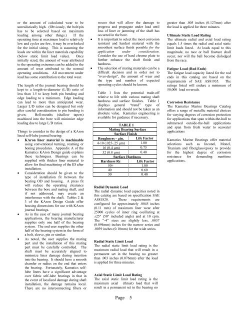
Table 1 lists the potential trade-off<br />
relative to life with various mating shaft<br />
hardness and surface finishes. Table 1<br />
displays general “trend” type of<br />
information and should not be taken as an<br />
absolute value. <strong>Kamatics</strong> engineering is<br />
available for guidance if necessary.<br />
TABLE 1<br />
Mating Bearing Surface<br />
Surface Finish<br />
Roughness - in. Life Factor<br />
4-10 (.025-.25 m) 1.00<br />
16 (0.4 m) 0.75<br />
32 (0.8 m) 0.40<br />
Surface Hardness<br />
Hardness Rc Life Factor<br />
50+ 1.00<br />
40 0.60<br />
30 0.40<br />
Radial Dynamic Load<br />
The radial dynamic load capacities noted in<br />
this catalog are based on specification SAE<br />
AS81820. These requirements are<br />
configured for approximately .0045 inches<br />
(0.11 mm) of maximum liner wear after<br />
25000 cycles of inner ring oscillating at<br />
±25° (50° included angle) and at 10 cpm.<br />
The “-4” sizes are slightly less, .0037<br />
(0.094mm) inches for the narrow series and<br />
.0039 inches (0.10mm) for the wide series.<br />
Radial Static Limit Load<br />
The radial static limit load rating is the<br />
maximum radial load that will result in a<br />
permanent set in the bearing no greater<br />
than .003 inches (0.076mm) after the load<br />
is applied for three minutes.<br />
Axial Static Limit Load Rating<br />
The axial static limit load rating is the<br />
maximum axial (thrust) load that will<br />
result in a permanent set in the bearing no<br />
Page 5<br />
greater than .005 inches (0.127mm) after<br />
the load is applied for three minutes.<br />
Ultimate Static Load Rating<br />
The ultimate radial and axial load rating<br />
equals 1.5 times the radial and axial static<br />
limit loads listed. At loads equal to this<br />
magnitude, no race or ball fracture shall<br />
occur, nor will the ball become dislodged<br />
from the race.<br />
Fatigue Load (Rod Ends)<br />
The fatigue load capacity listed for the rod<br />
ends in this catalog are based on the<br />
requirements of SAE AS81935. The<br />
ratings listed will endure a minimum of<br />
50,000 load reversals.<br />
Corrosion Resistance<br />
The <strong>Kamatics</strong> Marine <strong>Bearings</strong> Catalog<br />
offers a range of metallic material choices<br />
for varying degrees of corrosion protection<br />
for applications that span within-the-hull to<br />
submersed outside-the-hull applications<br />
and span from fresh water to seawater<br />
applications<br />
<strong>Kamatics</strong> Marine <strong>Bearings</strong> offer material<br />
selections such as Inconel, Monel,<br />
Titanium and fiberglass/epoxy to provide<br />
for the highest degree of corrosion<br />
resistance for demanding maritime<br />
applications.