Kamatics Karon Design Guide - Kaman Corporation
Kamatics Karon Design Guide - Kaman Corporation
Kamatics Karon Design Guide - Kaman Corporation

You also want an ePaper? Increase the reach of your titles
YUMPU automatically turns print PDFs into web optimized ePapers that Google loves.
KAMATICS CORPORATION<br />
KAMATICS KARON ® <strong>Design</strong> <strong>Guide</strong><br />
1. <strong>Kamatics</strong> in General<br />
• Types of bearings manufactured<br />
• Salvaging Components<br />
• Fretting Protection<br />
• Corrosion Protection<br />
• Liner Application<br />
• <strong>Design</strong> Comments<br />
2. Journal Bearings<br />
• Metallic Backed<br />
• Composite Backed<br />
• Solid KAron<br />
3. Spherical Bearings<br />
• Spherical Bearings<br />
• Rod End Bearings<br />
4. KRP Bearings (rolling element equivalents)<br />
• Track Roller / Cam Followers<br />
• Linkage/Pivot Bearings<br />
5. KAron Wear Strip Material<br />
• Description and usage<br />
Rev E, 03/04/05<br />
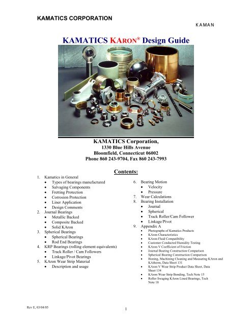
KAMATICS <strong>Corporation</strong>,<br />
1330 Blue Hills Avenue<br />
Bloomfield, Connecticut 06002<br />
Phone 860 243-9704, Fax 860 243-7993<br />
Contents:<br />
1<br />
KAMAN<br />
6. Bearing Motion<br />
• Velocity<br />
• Pressure<br />
7. Wear Calculations<br />
8. Bearing Installation<br />
• Journal<br />
• Spherical<br />
• Track Roller/Cam Follower<br />
• Linkage/Pivot<br />
9. Appendix A<br />
• Photographs of <strong>Kamatics</strong> Products<br />
• KAron Characteristics<br />
• KAron Fluid Compatibility<br />
• Customer Conducted Humidity Testing<br />
• KAron V Coefficient of Friction<br />
• Journal Bearing Construction Comparison<br />
• Spherical Bearing Construction Comparison<br />
• Honing, Machining Cleaning and Measuring KAron and<br />
KAtherm, Data Sheet 131<br />
• KAron V Wear Strip Product Data Sheet, Data<br />
Sheet 134<br />
• KAron Wear Strip Bonding, Tech Note 15<br />
• Roller Swaging KAron Lined Bearings, Tech<br />
Note 18
KAMATICS CORPORATION<br />
1. <strong>Kamatics</strong> in General:<br />
<strong>Kamatics</strong> <strong>Corporation</strong> manufactures<br />
self-lubricating bearings from common<br />
and exotic materials. The liner materials<br />
used in the bearings are designated as<br />
KAron for temperatures to 400°F<br />
(204°C), KAtherm for temperatures to<br />
600°F (315°C), and KAcarb for<br />
temperatures to 1200°F (635°C). These<br />
three systems encompass a family of<br />
self-lubricating bearing liners providing<br />
low friction, high load capacity, long life<br />
with low rates of wear and a large<br />
temperature range. They were<br />
developed solely by <strong>Kamatics</strong> to be used<br />
primarily as self-lubricating bearing<br />
liners in a variety of applications. This<br />
design guide will concentrate on the<br />
KAron system.<br />
KAron is a combination of thermosetting<br />
resin and filler materials in particle or<br />
fiber form. This differs significantly<br />
from other self-lubricating materials in<br />
that there are no continuous<br />
interconnecting fibers or weave that can<br />
provide a moisture path to the bonding<br />
substrate. A moisture path may either<br />
promote corrosion under the liner or<br />
significant liner swelling when used in a<br />
moisture-laden environment.<br />
KAron liner systems are homogenous in<br />
nature, a mixture of resin,<br />
polytetrafluoroethylene (PTFE) and<br />
other special fillers. Because of this,<br />
consistent friction and extremely low,<br />
linear, rates of wear can be expected<br />
throughout the life of the liner. Other<br />
self-lube materials are generally made<br />
up of a fabric blanket with different<br />
strata of PTFE, fiberglass, nylon, resin<br />
etc. and consistent performance cannot<br />
be anticipated throughout its thickness.<br />
2<br />
KAMAN<br />
Characteristics considered in the<br />
formulation of KAron include load<br />
carrying capability, operating<br />
temperature, coefficient of friction,<br />
sliding/rubbing velocities or any<br />
combination of these.<br />
Figure 1<br />
Typical KAron Lined Roller<br />
In addition to typical bearing<br />
applications, a KAron liner has other<br />
valuable uses including:<br />
• Salvaging Components – KAron<br />
can be applied in various thicknesses<br />
providing a method of salvaging<br />
components with oversize bores,<br />
undersize OD’s, worn or damaged<br />
surfaces, etc. Such applications can<br />
be rapidly addressed by a <strong>Kamatics</strong><br />
representative as to the suitability of<br />
<strong>Karon</strong> as a solution.<br />
• Fretting Protection – KAron can be<br />
used as an inexpensive barrier to<br />
eliminate/prevent damaging contact<br />
between expensive components. In<br />
many cases, KAron can be used as<br />
“applied” without any subsequent<br />
machining<br />
• Corrosion Protection – KAron has<br />
demonstrated limited protection<br />
against corrosion while providing a<br />
bearing material that can be<br />
machined to very close tolerances.<br />
KAron is well accepted throughout the<br />
industry. Oil exploration, aircraft, space,<br />
marine, nuclear power, hydropower, are<br />
just some of areas successfully using
KAMATICS CORPORATION<br />
KAron. The operating conditions and<br />
parameters vary widely. For example:<br />
• Temperature ranges from cryogenic<br />
to over 400° F (205° C).<br />
• Static contact pressures in excess of<br />
100,000 psi (690 mPa).<br />
• Short term operating velocities of<br />
100 feet/minute (30 meters/min) or<br />
higher.<br />
• Liner thickness up to 0.060” (1.5<br />
mm).<br />
• Operation with contaminates such as<br />
oil, grease, sand, grit, deicer,<br />
hydraulic fluid and cleaning fluids,<br />
and others.<br />
• Requirement to adhere to various<br />
materials including stainless and<br />
carbon steels, titanium, copper,<br />
nickel and aluminum alloys,<br />
fiberglass, carbon fiber and others.<br />
• The need to operate against various<br />
materials, hardnesses, and surface<br />
finishes.<br />
KAron has definite thickness associated<br />
with it. It is not a thin “dry film<br />
lubricant” that can be applied after final<br />
machining without affecting dimensions.<br />
Therefore, space must be provided for<br />
the liner when designing components<br />
that will include KAron. Liner<br />
thicknesses normally range between<br />
0.010 to 0.015 inches (0.25 to 0.38mm).<br />
Liner thickness is also a function of the<br />
amount of wear or clearance a system<br />
can tolerate and continue to operate as<br />
intended. For applications where<br />
clearance is not an issue, the liner<br />
thickness can be increased.<br />
Liner Application<br />
Prior to its application, the surface to be<br />
lined should be abraded (roughened) and<br />
cleaned to insure optimum adhesion.<br />
The abrading is accomplished by<br />
spraying special abrasive media at<br />
precise velocities and distances. If the<br />
surface to which the liner is to be applied<br />
3<br />
KAMAN<br />
has been shotpeened, the roughening<br />
will be kept to a minimum. This is to<br />
minimize any adverse effects to the<br />
shotpeening. Cleaning of the pre-lined<br />
surface is accomplished with chemicals<br />
that will not affect the properties of the<br />
base material. The liner is applied and<br />
cured at temperatures that will not affect<br />
the mechanical properties of the<br />
substrate.<br />
Applications such as pistons, complex<br />
housings, or similar, require design<br />
considerations that may not be readily<br />
apparent. This is especially true in cases<br />
where the customer intends to fabricate<br />
the part minus the liner and then send it<br />
to <strong>Kamatics</strong> for liner application.<br />
Surfaces that are not KAron lined may<br />
require protection from the abrading<br />
process. This can be a labor-intensive<br />
process involving masking. Cost savings<br />
can be realized by providing extra<br />
material on the non-lined surfaces<br />
allowing them to be roughened along<br />
with the lined area and later machined to<br />
the final dimensions. As KAron is<br />
normally machined after application, the<br />
extra time to machine the adjacent<br />
surface is minimal. Figure 2 illustrates<br />
this technique. The substrate material<br />
and KAron liner will be machined in the<br />
same setup, resulting in an excellent<br />
blending of the two. <strong>Kamatics</strong> provides<br />
the customer with guidance and/or “preliner”<br />
configuration drawings to<br />
coordinate this concept.<br />
Blank KAron Lined Final Machined<br />
Figure 2
KAMATICS CORPORATION<br />
Frequently <strong>Kamatics</strong> will require the<br />
same machining datum the customer<br />
used to generate the pre-lined surface.<br />
This is for proper tolerance and position<br />
of the final KAron lined surface. Any<br />
such datum should be identified and<br />
agreed upon in advance of any part<br />
fabrication.<br />
<strong>Design</strong> Comments:<br />
• Unless the bearing is molded to size,<br />
the KAron liner is normally<br />
machined after its application.<br />
Therefore, the requirement to hold<br />
very close pre-liner dimensions and<br />
smooth surface finishes prior to<br />
lining is not necessary. Tolerances<br />
of ± .002” (0.05 mm) and 125-250<br />
rms (0.8-1.6 um) surface finish on<br />
the area to be lined is adequate.<br />
• KAron is unaffected by chromium,<br />
cadmium, anodize, and alodine<br />
solutions. It is not necessary to<br />
protectively mask the liner during<br />
these operations. Because of this,<br />
the intersection between the plating<br />
and liner is virtually gap free.<br />
KAron is considered an electrical<br />
insulator where plating is concerned.<br />
Normal electrical conductivity<br />
through the liner to substrate is<br />
extremely difficult and cannot be<br />
relied upon in normal liner<br />
thicknesses.<br />
2. Journal Bearings<br />
<strong>Kamatics</strong> <strong>Corporation</strong> has been<br />
designing and manufacturing selflubricating<br />
journal bearings for over 30<br />
years. The original self-lube bearing<br />
was manufactured from compact carbon<br />
sleeves shrunk-fit into metallic housings.<br />
Operating capability of this combination<br />
exceeded 1000°F (538°C) and is still in<br />
use. They are offered as “KAcarb”<br />
bearings. Since then, technological<br />
advancements have extended <strong>Kamatics</strong><br />
products into a larger family of self-lube<br />
4<br />
KAMAN<br />
liner systems, all exhibiting low friction,<br />
low rates of wear, and temperatures<br />
ranging from cryogenic to over 1000°F<br />
(538°C).<br />
The majority of journal bearings<br />
(flanged or non-flanged) are<br />
manufactured with a metallic backing.<br />
The backing can be just about any metal<br />
but it is predominately stainless steel and<br />
aluminum. However, most composite<br />
structures require that the bearing be<br />
compatible with the structure. <strong>Kamatics</strong><br />
<strong>Corporation</strong> manufactures a large size<br />
range of KAron lined bearings with<br />
composite backings. Carbon/epoxy and<br />
fiberglass/epoxy are the most common<br />
composite combinations used.<br />
Composite Bearings<br />
<strong>Kamatics</strong> has “state-of-the-art” computer<br />
controlled filament winding and braiding<br />
capabilities. Composite backed<br />
bearings in excess of 40 inches (1 meter)<br />
have been produced. <strong>Kamatics</strong> KAron<br />
lined/composite backed bearings are<br />
qualified to MIL-B-85560. Composite<br />
bearings for operation at temperatures to<br />
600°F (315°C) are possible with our<br />
KAtherm technology.<br />
<strong>Kamatics</strong> also produces bearings made<br />
from solid KAron…without any<br />
backing for those applications where<br />
space is limited. Solid KAron bearings<br />
are normally pressed in, or bonded to, a<br />
housing and when installed have similar<br />
load and performance capabilities of<br />
metal or composite backed KAron<br />
bearings.
KAMATICS CORPORATION<br />
Journal Bearing <strong>Design</strong>:<br />
A suggested approach to the design of<br />
both flanged and non-flanged KAron<br />
self-lubricating journal bearings is<br />
offered below.<br />
The bearing pressure distribution used in<br />
the following equations is in a simplified<br />
form. Forgoing extensive discussion on<br />
actual pressure distribution and for<br />
calculation purposes, assume the area<br />
supporting the load to be a “projected<br />
area” pressure as defined in Equation 1.<br />
Projected<br />
Area<br />
Figure 3, (Non-flanged Journal)<br />
Projected<br />
Area<br />
Figure 4, (Flanged Journal)<br />
Equation 1; Journal bearing pressure;<br />
S=P/A, where;<br />
• S = Pressure (projected area)<br />
• P = Applied load (force)<br />
• A = D x LEFF<br />
• D = Nominal journal ID<br />
• L = Nominal length of the journal<br />
(including the flange if there is one)<br />
5<br />
KAMAN<br />
• LEFF = L minus “edge effects”<br />
The “edge effects” are the non-load<br />
supporting chamfers and the area under<br />
the flange, in the case of flanged<br />
journals. The “Projected Area” concept<br />
defined is widely used in the bearing<br />
industry and most published load ratings<br />
are based on this concept.<br />
Sizing of the journal bore is based upon<br />
a combination of load, shear and tensile<br />
allowables of the bolt/pin material plus<br />
any bending under load. The bearing<br />
stress on the bearing should be checked<br />
once the bolt/pin diameter has been<br />
established.<br />
It is important to be as accurate as<br />
possible when determining forces and<br />
both normal operating and maximum<br />
forces are required. For instance,<br />
supplying and calculating size based<br />
only on the maximum force coupled<br />
with an operation or flight spectrum may<br />
cause the bearing to be larger than<br />
necessary or the amount of calculated<br />
wear to be unrealistically high.<br />
(Obviously, the bolt/pin has to be<br />
selected based on maximum loading<br />
among other things.) If the operating<br />
time at maximum load is relatively low<br />
and cycles are few, it may be overlooked<br />
for the initial sizing. This is assuming<br />
the loads are within the liner materials<br />
capability (below static limit load value).<br />
Once initially sized, the amount of wear<br />
attributed to the operating extremes can<br />
be added to the amount of wear<br />
attributed to the normal operating<br />
conditions. All movement under load<br />
has some contribution to the total wear.<br />
The length of the journal bearing should<br />
be kept to a length-to-diameter (L/D)<br />
ratio of less than 1.5 to keep both pin<br />
bending and edge loading to a minimum.<br />
Edge loading can lead to more than<br />
anticipated wear. Larger L/D ratios can
KAMATICS CORPORATION<br />
be designed but only after careful<br />
consideration to pin bending is given.<br />
Bell-mouths (shallow tapers) machined<br />
into the bore will minimize edge loading<br />
due to large L/D ratios.<br />
Things to consider in the design of a<br />
KAron lined self-lube journal bearing:<br />
• KAron liner material is machineable<br />
using conventional turning, reaming<br />
or honing procedures. Appendix A<br />
explains these techniques. Bearings<br />
can be supplied with thicker liner<br />
material to allow final machining of<br />
the ID after installation.<br />
• Consideration should be given to the<br />
type of installation fit between the<br />
bearing OD and housing. A press fit<br />
will reduce the operating clearance<br />
between the bore and mating shaft,<br />
and if not addressed, may create an<br />
interference with the shaft. Tables 2<br />
& 3 offer housing dimensions for use<br />
with <strong>Karon</strong> journal bearings.<br />
• As in the case of many journal<br />
bearing applications, the bearing<br />
manufacturer supplies only one half<br />
of the bearing system. The end user<br />
supplies the other half (the inner<br />
race) in the form of a bolt, sleeve,<br />
pin, or similar.<br />
• As noted, the user supplies the<br />
mating part and the installation of<br />
this part must be carefully controlled.<br />
The shaft must be accurately aligned<br />
to minimize liner damage during<br />
insertion into the bearing. It should<br />
have a smooth chamfer or radius on<br />
the end that enters the bearing.<br />
Fortunately, <strong>Kamatics</strong> self-lube<br />
liners have a significant advantage<br />
over fabric self-lube liners in that in<br />
the event of localized damage during<br />
shaft installation, the damage<br />
remains local. There are no<br />
interconnecting fibers or weave that<br />
will allow the damage to progress<br />
and propagate under load until loss<br />
6<br />
KAMAN<br />
of liner or jamming of the shaft has<br />
occurred in the bore.<br />
• It is important to select the most<br />
corrosion resistant and hardest<br />
•<br />
material with the smoothest surface<br />
finish possible for the application<br />
under consideration. Consider the<br />
use of hard chrome plate to further<br />
enhance the shaft finish.<br />
The selection of mating materials<br />
can be a difficult decision and in<br />
order not to “over-design”, the<br />
amount of wear and the type and<br />
number of expected operating cycles<br />
should be known.<br />
• Table 4 lists the potential trade-off<br />
relative to life with various mating<br />
shaft hardnesses and surface finishes.<br />
Table 4 displays general “trend” type<br />
of information and should not be<br />
taken as an absolute value. <strong>Kamatics</strong><br />
engineering is available for guidance<br />
if necessary.<br />
3. Spherical Bearings<br />
<strong>Kamatics</strong> <strong>Corporation</strong> has designed and<br />
manufactured self-lubricated spherical<br />
bearings since 1966. The original<br />
<strong>Kamatics</strong> spherical bearing was made<br />
from compacted carbon matrix liners<br />
operating against a chrome oxide coated<br />
and polished surface. This was known<br />
as a “KAcarb” bearing and is still in use<br />
today for applications operating at<br />
temperatures up to 1200°F degrees F<br />
(635°C). Today, as mentioned<br />
previously, <strong>Kamatics</strong> manufactures<br />
spherical bearings with KAron self-lube<br />
liners for temperatures to 400°F (204°C)<br />
and KAtherm for temperatures to 600°F<br />
(315°C). Contact your <strong>Kamatics</strong><br />
representative for further information for<br />
KAtherm and KAcarb applications.
KAMATICS CORPORATION<br />
Spherical Bearing <strong>Design</strong>:<br />
The design criterion for a KAron lined<br />
spherical bearing is similar to the criteria<br />
for a journal bearing. The major<br />
difference is that the inner race is<br />
supplied within the bearing assembly<br />
and its hardness, surface finish and<br />
corrosion resistance is normally left up<br />
to the bearing manufacturer.<br />
Equation 2 provides a method for<br />
calculating bearing pressures for<br />
spherical bearings and is similar to the<br />
journal bearing “projected area”<br />
approach.<br />
Important Note: <strong>Kamatics</strong> <strong>Karon</strong> lined<br />
spherical bearings incorporate a unique<br />
“cathedral” shaped cavity between the<br />
ball OD and outer race ID. This feature<br />
“locks” the liner within the bearing<br />
overcoming the familiar problem of liner<br />
loss suffered with many fabric lined<br />
bearings. Figure 5 shows the<br />
“cathedral” feature.<br />
Figure 5<br />
Some other important design<br />
considerations relative to the design of<br />
spherical bearings follow:<br />
Cathedral Cavity<br />
• It is imperative that the spherical<br />
surface of the ball be as hard, smooth<br />
and corrosion resistant as possible.<br />
• There should be sufficient clamp-up<br />
torque applied to the ball faces to<br />
insure that motion takes place<br />
between the ball OD and outer race<br />
liner unless movement within the<br />
bore is required.<br />
• For applications where it is difficult<br />
to generate enough preload on the<br />
7<br />
KAMAN<br />
ball to prevent rotation between the<br />
bore and bolt/shaft, <strong>Kamatics</strong> can<br />
supply the bearing with a KAron<br />
liner in the bore and side faces. This<br />
will eliminate damage to mating<br />
surfaces in the event that motion<br />
takes place in the bore.<br />
• Consideration should be given to the<br />
type of installation fit between the<br />
bearing OD and housing. A press fit<br />
will reduce the operating clearance<br />
between the ball and outer race and<br />
increase the breakout torque if there<br />
is initial torque. Either condition<br />
may be acceptable for the<br />
application. The designer is just<br />
cautioned to consider the<br />
consequences of the fit.<br />
• Similar consideration should be<br />
given to the fit between the ball bore<br />
and bolt as noted above. A designer<br />
is cautioned not to use an<br />
interference fit between the ball and<br />
bolt if the ball is hardened 440C<br />
stainless steel or other materials that<br />
may be prone to stress cracking<br />
when under tensile loads.<br />
• Like the previous suggestions for<br />
journal bearing installations, for<br />
those applications where the user<br />
intends to use a thermal fit technique<br />
(shrink fit) to install a KAron<br />
spherical bearing, a solution of dry<br />
ice and solvent in which to immerse<br />
the bearing is recommended.<br />
• To assist in housing size selection,<br />
Tables 5 and 6 offer typical housing<br />
dimensions for use with <strong>Karon</strong> lined<br />
spherical bearings.<br />
Equation 2; Spherical bearing pressure;<br />
S=P/A, where;<br />
• S = Pressure (projected area)<br />
• P = Applied load (force)<br />
• A = D(ball) x HEFF<br />
• D(ball) = Nominal ball OD<br />
• H = Nominal width of the outer race
KAMATICS CORPORATION<br />
• HEFF = H minus “edge effects”<br />
The “edge effects” are the possible nonload<br />
supporting liner setback allowances<br />
at each side face of the outer race. In the<br />
case of KAron lined spherical bearings,<br />
assume the setback at each side to be<br />
0.025 inches (0.63mm) or 0.050 inches<br />
(1.27mm) total “edge effect”.<br />
Figure 6,<br />
(Spherical Bearing Projected Area)<br />
Rod End Bearing <strong>Design</strong>:<br />
<strong>Kamatics</strong> has over 35 years of<br />
experience manufacturing rod end<br />
assemblies. Materials range from carbon<br />
steel to high nickel alloys. Bore sizes<br />
range from 0.060 inch (1.5mm) to 3.00<br />
inches (75mm) and larger. They are<br />
used in applications from farm<br />
equipment to space shuttles. <strong>Kamatics</strong><br />
rod ends operate at temperatures ranging<br />
from cryogenic to 1000°F (538°F) with<br />
KAron, KAtherm, and KAcarb liner<br />
systems. “<strong>Kamatics</strong> KAron Bearing<br />
Catalog – Spherical, Rod End, and<br />
Journal Sleeve Bearings” (KR-M series)<br />
offer some of the more standard sizes of<br />
rod ends available. Special sizes are<br />
produced upon request. Figure 7 shows<br />
a typical male threaded rod end<br />
assembly.<br />
The design of a rod end assembly<br />
requires a thorough understanding of the<br />
loads it will be subjected to. For<br />
8<br />
KAMAN<br />
example, if the loads are predominately<br />
compression (in the direction of the<br />
threads or shank), the banjo diameter<br />
(the hoop of metal around the bearing<br />
insert) can be thinner than if the rod end<br />
were used in tension. A tension load on<br />
the rod end body causes the hole in the<br />
body containing the bearing insert to<br />
become elongated (ovalized).<br />
Obviously, this elongation does not<br />
happen if the load is in compression (in<br />
the direction of the shank/threads) as the<br />
hole is not “stretched” in this direction.<br />
The elongation creates a “pinching”<br />
force on the bearing insert in the 3-9<br />
o’clock position relative to the shank.<br />
This can have two significant effects on<br />
the assembly. First is that it tends to<br />
increase the torque required to rotate the<br />
ball. If the magnitude of the torque<br />
increase is high enough, coupled with<br />
the normal operating torque, frequent<br />
oscillation or rotation of the ball may<br />
produce unanticipated bending stresses<br />
on the rod end body and possibly lead to<br />
a fatigue failure at the banjo/shank<br />
intersection.<br />
The second effect is relative micro<br />
motion between the housing ID and<br />
bearing OD at the 3-9 o’clock position<br />
as a consequence of the hole elongation.<br />
Frequent load reversals between tension<br />
and compression can lead to fretting<br />
between the bearing and rod end<br />
body…and eventual metal fatigue of the<br />
rod end. Classic rod end failures occur<br />
approximately 15-20 degrees below the<br />
3-9 o’clock position.<br />
A light interference fit between the<br />
bearing and rod end body is<br />
recommended to minimize the<br />
possibility of fretting. <strong>Kamatics</strong><br />
manufactures spherical bearings to be<br />
installed in the rod end body with<br />
internal clearance designed to
KAMATICS CORPORATION<br />
accommodate an interference fit without<br />
adding additional ball rotational torque.<br />
The rod end body should be completely<br />
analyzed to insure that; the shank/thread<br />
size is large enough to support the loads;<br />
the banjo diameter is thick enough to<br />
react applied forces and minimize hole<br />
elongation; the fillet radius between the<br />
banjo and shank/threads is of sufficient<br />
size and with as good a surface finish as<br />
possible to minimize stress<br />
concentrations.<br />
<strong>Kamatics</strong> is available to assist in the<br />
design of your rod end application.<br />
Figure 7 (male rod end assembly)<br />
4. “KRP” Track Roller, Cam<br />
Follower and Pivot Bearings:<br />
The design and manufacture of selflubricating<br />
track rollers, cam followers<br />
and typical airframe pivot bearings was<br />
and continues to be pioneered by<br />
<strong>Kamatics</strong> <strong>Corporation</strong>. It was obvious<br />
that there was an unfulfilled need for this<br />
type of bearing that would not be subject<br />
to the effects of corrosion, brinnelling,<br />
ball/roller/needle fracture and difficulty<br />
to grease that is common to conventional<br />
anti-friction bearings. The need to<br />
continually re-lubricate, the manpower<br />
required, not being sure that the<br />
lubricant ever reached the bearing, was<br />
and continues to be a concern. Also, by<br />
eliminating the grease requirement, the<br />
environment around the bearing remains<br />
much cleaner and not subject to the<br />
collection of grit, dirt etc. that is also<br />
9<br />
KAMAN<br />
common around greased assemblies.<br />
Looking under the wing or at a landing<br />
gear of a greased aircraft is enough to<br />
make one aware of the potential benefits<br />
of non-greased self-lubricated bearings.<br />
Track Rollers & Cam Followers:<br />
For the majority of track roller/cam<br />
follower applications the “KRP” design<br />
incorporates a KAron liner applied to the<br />
OD of the inner race and. Either KAron<br />
or PTFE filled Acetal resin is inserted<br />
between the side faces of the outer race<br />
and thrust members. This provides an<br />
additional benefit to the roller by<br />
providing a thrust capability not usually<br />
found in an anti-friction bearing of the<br />
same type. The outer race is made from<br />
a hard corrosion resistant stainless steel<br />
material, normally Custom 455, 440C or<br />
Cronidur 30 stainless steel, and a 17-4<br />
PH stainless steel inner race and thrust<br />
member(s). Depending upon the<br />
operating conditions, seals are included<br />
to minimize the entry of abrasive<br />
particles and contaminating fluids. The<br />
assembly is then either electron beam<br />
welded or swaged to keep the<br />
components together as an assembly.<br />
Figure 8 illustrates this <strong>Kamatics</strong> design<br />
approach.<br />
Figure 8 (clevis mounted roller)<br />
The design and load carrying capability<br />
of track rollers and cam followers<br />
depends heavily on the installation. That<br />
is, whether the bearing is installed<br />
between a clevis arrangement or is<br />
cantilevered off of structure. Of concern<br />
for a cantilevered (studded) roller is<br />
determining where the roller will contact
KAMATICS CORPORATION<br />
the mating track or cam. Figure 9<br />
shows a studded roller assembly.<br />
Figure 9, (stud mounted roller)<br />
The worst-case scenario is when the<br />
roller contact is at the extreme end of the<br />
outer race, away from the threaded end.<br />
The bending moment arm is the longest<br />
at this point, imparting maximum stress<br />
on the stud. This is not a problem unless<br />
the stud is not of sufficient size to safely<br />
react the implied stress. There are<br />
various methods to analyze the bending<br />
stresses in a cantilevered roller and this<br />
is normally the responsibility of the<br />
bearing user. The same concern as to<br />
where the outer race will contact the<br />
mating surface exists with a clevismounted<br />
assembly, however, the<br />
bending consideration is at a minimum.<br />
The concern here is more of track/cam<br />
contact and bolt shear stresses. Bolt<br />
shear is usually not a major concern as<br />
there is double shear involved with a<br />
clevis arrangement.<br />
There are ways to minimize the bending<br />
concern on a studded roller. One is to<br />
incorporate a “crown” radius on the OD<br />
of the roller in an attempt to bring the<br />
contact point nearer the center of the<br />
outer race width. This is the most<br />
common approach with anti-friction<br />
bearings, however, this ensures that the<br />
contact stresses on the track or cam will<br />
be high because of the more localized<br />
contact area. This is not a problem as<br />
long as the stresses are within the<br />
material’s capabilities.<br />
A second approach to minimizing both<br />
the bending and contact stress<br />
considerations is the patented <strong>Kamatics</strong><br />
10<br />
KAMAN<br />
self-aligning roller. This design<br />
incorporates a KAron lined spherical<br />
inner race that operates against the same<br />
hardened outer race material as the more<br />
common “KRP” design. The spherical<br />
feature allows the roller to conform/align<br />
to the mating track/cam surface without<br />
the high contact stresses and with a<br />
reduced bending moment arm that can<br />
be considered to pass through the<br />
centerline of the outer race width.<br />
Figure 10 illustrates the self-aligning<br />
design.<br />
Figure 10, (self-aligning roller)<br />
Extensive testing and field results have<br />
shown that a KAron lined track roller<br />
will operate successfully for an extended<br />
duration at dynamic bearing pressures as<br />
high as 20,000 psi (140 mPa). For most<br />
commercial aircraft flap/slat roller<br />
applications or similar, by keeping the<br />
bearing pressures to a maximum of<br />
12,000 psi (85mPa), the roller can<br />
yield in excess of 200,000 revolutions<br />
of useful life with liner wear less than<br />
0.004 inches (0.10mm). As is obvious,<br />
if as many as 200,000 revolutions are not<br />
required, the bearing pressures can be<br />
increased. This is normally the case of<br />
military aircraft, where space is small,<br />
loads are higher but the number of<br />
cycles is lower. <strong>Kamatics</strong> engineering is<br />
available to assist in sizing the roller for<br />
any application under consideration.<br />
“KRP” Linkage/Bellcrank Pivot Bearings:<br />
Prior to the <strong>Kamatics</strong> self-lube KRP<br />
design, the typical linkage/bellcrank<br />
pivots bearings were mainly limited to<br />
ball bearings or greased journal bearings.<br />
The “KRP” design for these applications
KAMATICS CORPORATION<br />
also incorporate a design similar to the<br />
track roller/cam follower with an<br />
internal self-lube liner, but without the<br />
hardened outer race. Because this type<br />
of bearing is contained/pressed within a<br />
housing the need for a hardened outer<br />
race does not normally exist. In<br />
“linkage/bellcrank” KRP, the self-lube<br />
liner is applied to the ID and side faces<br />
of the outer race and the inner race is of<br />
sufficient hardness to provide the hard,<br />
abrasion-resistant surface necessary for<br />
optimum performance. Figure 11<br />
illustrates this design.<br />
Figure 11<br />
(“KRP” Linkage/Bellcrank Bearing)<br />
Table 8 offers some recommended<br />
housing and shoulder dimensions for<br />
installation.<br />
<strong>Kamatics</strong> “KRP” catalog offers selflubricated<br />
designs that are dimensionally<br />
equivalent to many of the more<br />
commonly used ball, needle and roller<br />
bearings used in the industry today.<br />
They all feature the benefit of a liner<br />
system that is not prone to problems<br />
associated with anti-friction bearings.<br />
Problems such as race brinnelling,<br />
rolling element failure, greasing<br />
difficulties (including the requirement to<br />
get the grease to the bearing) and the<br />
manpower needed to maintain the<br />
bearing.<br />
For load-carrying capability of a KRP<br />
bearing, calculations based on the<br />
projected area concept, similar to that<br />
previously discussed for <strong>Kamatics</strong><br />
journal bearings should be used. A KRP<br />
linkage/bellcrank bearing normally<br />
experiences race oscillation as opposed<br />
to race rotation for track roller/cam<br />
11<br />
KAMAN<br />
follower bearings. The data in Table 7<br />
along with Equations 3 or 4 and 5 can<br />
be used to determine probable liner<br />
wear.<br />
5. Wear Strip Material:<br />
<strong>Kamatics</strong> <strong>Corporation</strong> offers a unique<br />
method of obtaining the KAron liner<br />
system in sheet or strip form for special<br />
applications. To date, the majority of<br />
applications for this material have been<br />
in problem areas involving unintentional<br />
rubbing, scuffing or fretting. It can also<br />
be used when the component to be lined<br />
is either too large or too costly to<br />
transport to <strong>Kamatics</strong> for the<br />
conventional liner application. Figure<br />
12 shows some typical wear strip<br />
configurations.<br />
The <strong>Kamatics</strong> KAron wear strip material<br />
is in the form of a fiberglass/epoxy<br />
backing of variable thickness, with the<br />
KAron V liner system applied to one or<br />
both sides of the fiberglass. The normal<br />
operating temperature range for KAron<br />
lined wear material is –65°F (-54°C) to<br />
+250°F (+120°C). Operating<br />
temperatures up to +500°F (+260°C) are<br />
possible with KAtherm T87. Consult<br />
<strong>Kamatics</strong> engineering for further<br />
information on the use of high<br />
temperature wear material.<br />
Wear strip products are applied by<br />
bonding the material onto the substrate<br />
with no further machining of the KAron<br />
surface anticipated. If necessary,<br />
<strong>Kamatics</strong> can supply complete data for<br />
the bonding process along with<br />
suggested structural adhesives. Wear<br />
strip products consisting of KAron<br />
applied onto both surfaces of the<br />
fiberglass/epoxy backing are not bonded<br />
onto a substrate. These products are<br />
generally stamped to size for use as<br />
thrust washers.
KAMATICS CORPORATION<br />
Light Duty and Medium Duty KAron<br />
lined wear strip material is stocked at<br />
<strong>Kamatics</strong> for immediate delivery. Light<br />
Duty material, KAron applied to one<br />
side, is approximately 0.018 inches<br />
(0.46mm) thick with a nominal KAron<br />
thickness of 0.008 inches (0.20mm).<br />
Medium Duty material, KAron also<br />
applied to one side, is approximately<br />
0.036 inches (0.91mm) thick with a<br />
nominal KAron thickness of 0.016<br />
inches (0.41mm). Maximum width<br />
length dimensions are 12 inches<br />
(300mm) x 48 inches (1200mm). Other<br />
thickness/size combinations can be<br />
manufactured in an expeditious manner<br />
to support programs under consideration.<br />
Unless directed otherwise, the typical<br />
wear strip material is supplied with a<br />
“peel-ply” removable release film on the<br />
side opposite the KAron surface. Once<br />
removed the surface is ready for<br />
bonding. Removal of the peel-ply leaves<br />
a clean, roughened textured surface,<br />
perfect for the bonding operation.<br />
Data sheets explaining the properties of<br />
KAron V Wear Strip material is shown<br />
in Addendum A.<br />
Figure 12<br />
Typical Wear Strip Shapes<br />
6. Bearing Motion;<br />
After the bearing pressures have been<br />
arrived at, the rubbing velocity of the<br />
bearing surfaces and total rubbing<br />
distance traveled should be determined.<br />
There are several equations to do this<br />
12<br />
KAMAN<br />
and the units are normally expressed in<br />
feet per minute (FPM) for velocity and<br />
feet for distance.<br />
Equation 3; velocity - oscillation<br />
V (Oscillation) = ((α∗CPM) / (360))∗((D∗π) / 12)),<br />
where;<br />
• V = Velocity in feet per minute<br />
• α= Number of degrees per cycle<br />
• CPM = Cycles per minute<br />
• D = Journal ID or ball OD<br />
• 360 = 360° per revolution<br />
• 12 = 12 inches per foot<br />
Calculating the number of degrees per<br />
cycle should be calculated using the<br />
method shown in Figure 13. Figure 13<br />
graphically shows what is understood<br />
when the oscillation angle is stated to be<br />
±α° (α indicating any arbitrary angle).<br />
It is generally understood that ±α°<br />
means “α° times 4”, i.e. ±25° = 100°<br />
total per cycle. It is not the total<br />
included angle times 4. It is extremely<br />
important to be accurate on this point<br />
otherwise we may have doubled or<br />
halved the motion, leading to erroneous<br />
wear approximations.<br />
Equation 4; distance - oscillation<br />
d (Oscillation) = ((π∗D∗α/360)∗N)/12,<br />
where;<br />
• d = Rubbing distance traveled in feet<br />
• D = Journal ID or ball OD<br />
• α = Total degrees per cycle<br />
• N = Number of cycles (oscillations)<br />
• 12 = 12 inches per foot<br />
• π = 3.14159…
KAMATICS CORPORATION<br />
(-) (+)<br />
Figure 13,<br />
Oscillation Angle (α) Definition<br />
Equation 5; velocity - rotation<br />
V (Rotation)=(D∗π∗RPM)/ 12, where;<br />
• V = Velocity in feet per minute<br />
• RPM = Revolutions per minute<br />
• D = Journal ID or ball OD<br />
• π = 3.14159…<br />
• 12 = 12 inches per foot<br />
Equation 6; distance - rotation<br />
d (Rotation) = ((π∗D∗N)/12<br />
where;<br />
• d = Rubbing distance traveled in feet<br />
• D = Journal ID or ball OD<br />
• N = Number of revolutions<br />
• π = 3.14159 …<br />
• 12 = 12 inches per foot<br />
PV Values, (Pressure x Velocity)<br />
When both bearing pressure (P) and<br />
velocity (V) are determined, the product<br />
of the two is a quantity known as “PV”.<br />
This is a value that is used to assist in<br />
determining liner wear at various<br />
operating conditions.<br />
At <strong>Kamatics</strong>, many years of endurance<br />
test data have been generated for <strong>Karon</strong><br />
liner materials at various pressures,<br />
velocities, and temperatures.<br />
Table 7 displays typical rates of liner<br />
wear at various PV levels based on a<br />
13<br />
KAMAN<br />
laboratory environment. The rate of<br />
wear is given in inches of wear, per inch<br />
of liner travel, at various bearing<br />
pressures.<br />
It should be emphasized that when<br />
considering PV values, one realizes that<br />
a self-lube liner is normally used at<br />
velocities less than 20 FPM…and at<br />
relatively low bearing pressures at this<br />
velocity.<br />
For example, a typical helicopter tail<br />
rotor pitch bearing may operate at<br />
bearing pressures of 2000 psi (14 mPa)<br />
and at a velocity of 20 fpm. This<br />
equates to a PV value of 40,000.<br />
Similarly, an aircraft slat actuator may<br />
operate at a bearing pressure of 20,000<br />
psi (140 mPa) and at a velocity of 2 fpm<br />
for a PV value of 40,000. Both are<br />
within acceptable PV limits however<br />
you would not use the same liner<br />
material for both applications. You<br />
would use a liner grade that is<br />
formulated for either high speed or high<br />
load. It would not be advisable to<br />
operate at a pressure of 20000 psi and at<br />
a velocity of 20 fpm (a PV of 400,000)<br />
for any appreciable amount of time.<br />
For most applications, keeping the PV to<br />
50,000 or less will yield relatively long<br />
bearing life.<br />
“Life” itself has to be carefully<br />
considered as to how long the bearing<br />
must operate without exceeding an<br />
acceptable amount of wear/clearance. If<br />
the application under consideration is<br />
required to operate for a relatively short<br />
period of time, it is quite conceivable<br />
that PV values in excess of 100,000 can<br />
be acceptable...again, depending on the<br />
duty requirements of the bearing. Any<br />
time the requirement is for a PV in<br />
excess of 50,000, <strong>Kamatics</strong> engineering<br />
should be contacted for advice.
KAMATICS CORPORATION<br />
7. Wear Calculations:<br />
Equation 7 incorporates values obtained<br />
from Table 7 to arrive at a predicted<br />
amount of liner wear after an assumed<br />
operation sequence.<br />
Equation 7; Wear Calculation<br />
W = k ∗ d<br />
where;<br />
W = total liner wear in inches<br />
k = wear rate from Table 7, in inches of<br />
liner wear per foot of liner travel.<br />
d = total liner distance traveled in feet<br />
obtained from Equations 4 or 6.<br />
Example: Assume a typical application<br />
is operating at a bearing pressure (P) of<br />
25,000 psi, at an average rubbing<br />
velocity (V) of 1.5 feet per minute and<br />
for a distance of 5000 feet. The product<br />
of the “P” and “V” is well within the<br />
allowable range noted earlier. From<br />
Table 7, locate the point where the<br />
25,000 psi ordinate intersects the “wear”<br />
curve, and follow this intersection point<br />
to the left, parallel to the “x” axis and<br />
obtain the “k” wear factor of 3800 E -10<br />
or 3.8 E -7 . Multiply this “k” factor times<br />
the number of feet traveled and obtain<br />
the amount of liner wear of 0.002 inches<br />
(0.05mm) of liner wear. To this add<br />
0.0005 inches (0.013mm) of “liner seatin”<br />
that may occur within the first 100<br />
feet of travel, for a potential total liner<br />
wear of 0.0025 inches (0.063mm).<br />
8. Bearing Installation:<br />
There has been much written pertaining<br />
to bearing installation and many<br />
companies have established their own<br />
preferences. MIL-STD-1599 offers<br />
some excellent basic recommendations<br />
relative to fit-up and dissimilar metal<br />
considerations. The following is offered<br />
to complement MIL-STD-1599 with<br />
respect to <strong>Kamatics</strong> bearings.<br />
14<br />
KAMAN<br />
Journal Bearing Installation:<br />
The self-lube liner on a journal bearing<br />
is normally supplied unprotected other<br />
than standard wrapping and packaging.<br />
Once removed from its packaging,<br />
handling and installation damage can be<br />
a major concern.<br />
It is important to protect and not subject<br />
the liner from external damage during<br />
the installation process. The tool used to<br />
insert the bearing into the housing must<br />
be free of sharp corners with smooth<br />
beveled edges where it enters the<br />
bearing. The edges of the housing into<br />
which the bearing is being assembled<br />
should be chamfered to assist in<br />
centering the bushing.<br />
In the case of a journal with a lined<br />
flange, the insertion tool should have a<br />
surface as large as the flange OD to<br />
apply the insertion force against. This<br />
will protect the liner on the flange as<br />
well as the liner within the bore. The<br />
force applied to the bearing should be<br />
firm, steady and in one continuous<br />
effort. Pausing before complete<br />
insertion may cause galling of the<br />
bearing OD, housing bore or both.<br />
Figures 14 and 15 offer installation<br />
suggestions and Tables 2 and 3, housing<br />
and shaft sizes. Figure 16 shows<br />
various methods used to retain journal<br />
bearings.<br />
In applications where the user intends to<br />
use a thermal fit technique (shrink-fit) to<br />
install a KAron journal bearing,<br />
<strong>Kamatics</strong> recommends a solution of dry<br />
ice and an environmentally safe solvent<br />
in which to immerse the bearing. If the<br />
housing is to be heated to increase the<br />
bore size for easier entry of the bearing,<br />
the temperature used to heat the housing<br />
should not cause the bearing temperature<br />
to exceed 325°F (163°C).
KAMATICS CORPORATION<br />
INSERTION<br />
TOOL<br />
JOURNAL<br />
BEARING<br />
HOUSING INSTALLED<br />
BEARING<br />
Figure 14<br />
(Non-flanged Journal Bearing)<br />
INSERTION<br />
TOOL<br />
FLANGED<br />
JOURNAL<br />
BEARING<br />
HOUSING INSTALLED<br />
FLANGED<br />
BEARING<br />
Figure 15<br />
(Flanged Journal Bearing)<br />
VIEW A VIEW B<br />
TYPICAL PRESS<br />
FIT INSTL<br />
VIEW C<br />
PRESS OR SLIP<br />
FIT WITH<br />
DOUBLE SIDE STAKE<br />
PRESS OR SLIP<br />
FIT WITH<br />
SINGLE SIDE STAKE<br />
VIEW D<br />
PRESS OR SLIP<br />
FIT WITH HOUSING<br />
SHOULDER AND<br />
SINGLE SIDE STAKE<br />
VIEW E VIEW F<br />
PRESS OR SLIP<br />
FIT WITH DOUBLE<br />
SIDE HOUSING STAKE<br />
PRESS OR ADHESIVE<br />
INSTL. METALLIC<br />
OR COMPOSITE.<br />
Figure 16<br />
(Typical Journal Bearing Installation)<br />
Note: When a bearing is retained axially<br />
within the housing, the fit between the<br />
15<br />
KAMAN<br />
bearing and housing can be either a slip<br />
or press fit. The choice depends upon,<br />
among other things, the load applied to<br />
the bearing and the possibility of it<br />
chucking or rotating within the housing.<br />
A slip fit should be considered if there is<br />
concern that the bore will reduce too<br />
much as a result of the fit and interfere<br />
with the motion of the shaft. In the case<br />
of <strong>Kamatics</strong> lined bearings, this<br />
concern can be eliminated as the liner<br />
can be precisely machined after a<br />
press fit installation.<br />
View A, Figure 16 depicts the most<br />
common method of installing a flanged<br />
journal bearing with an interference fit.<br />
The designer is cautioned to remember<br />
that the interference will reduce the ID<br />
of the bearing. It is assumed that there is<br />
a thrust force in one direction only.<br />
View B (Fig 16) depicts an installation<br />
similar to View A, however, with the<br />
addition of a swaging groove on the side<br />
opposite the flange. The lip of the<br />
groove is deformed into a chamfer in the<br />
housing, preventing possible migration<br />
of the bearing from the housing.<br />
View C (Fig 16) depicts a non-flanged<br />
bearing installed with a swaging groove<br />
on both sides of the bearing. This will<br />
prevent the bearing from migrating out<br />
of the housing in either direction. Axial<br />
retention of the bearing is important<br />
especially if the shaft translates within<br />
the bore.<br />
View D (Fig 16) depicts a non-flanged<br />
bearing retained by a housing shoulder<br />
on one side and a single-side housing<br />
stake on the other.<br />
View E (Fig 16) depicts a bearing<br />
retained by two side housing staking<br />
grooves.
KAMATICS CORPORATION<br />
View F (Fig 16) depicts a bearing<br />
installed by either a press fit or a slip fit<br />
with a retaining adhesive to assist in<br />
maintaining position. The adhesive<br />
installation is very common with the use<br />
of composite bearings.<br />
VIEW A VIEW B<br />
DOUBLE SIDE<br />
RACE SWAGE<br />
VIEW C<br />
OUTER RACE<br />
THREADED INSERT<br />
SINGLE SIDE<br />
RACE SWAGE<br />
VIEW D<br />
DOUBLE SIDE<br />
HOUSING STAKE<br />
VIEW E VIEW F<br />
SINGLE SIDE<br />
HOUSING STAKE<br />
SNAP RING<br />
RETAINER<br />
Figure 17<br />
(Typical Spherical Bearing<br />
Installation)<br />
Spherical Bearing Installation<br />
There are various methods used to install<br />
spherical bearings. Figure 17 illustrates<br />
some of the more common installations.<br />
When installing a spherical bearing into<br />
its mating housing it is important to<br />
apply the force against the side face of<br />
the outer race and not against the ball.<br />
Pressing on the ball face may tend to<br />
“wedge” the ball into the outer race and<br />
affect the bearing torque. Similarly to<br />
journal bearings, the force to insert<br />
16<br />
KAMAN<br />
should be firm, steady and complete in<br />
one attempt. Use tooling to position the<br />
bearing before insertion if necessary to<br />
insure that the OD enters the housing<br />
properly. On those installations where<br />
the bearing is retained axially, the use of<br />
a small amount of lubricant to aid in the<br />
assembly process is acceptable. This is<br />
assuming it does not interfere with either<br />
the function of the bearing or any sealant<br />
application around the circumference of<br />
the joint after installation.<br />
View A, Figure 17 depicts the more<br />
standard outer race double swaged<br />
groove installation. This method<br />
provides axial retention and allows<br />
multiple bearing replacements without<br />
damaging the housing. Roll or anvil<br />
swaging tools accomplish the swaging or<br />
deforming of the groove into the housing<br />
chamfers. <strong>Kamatics</strong> Tech Note 18 offers<br />
roll swaging information as well as<br />
instructions as to how to manufacture<br />
swaging tools.<br />
View B (Fig 17) depicts another<br />
common installation where one side of<br />
the outer race has a pre-machined lip<br />
that nests into a housing chamfer and a<br />
groove on the opposite side to be swaged<br />
into a housing chamfer. This method<br />
assists in accurately positioning the<br />
bearing in the axial direction and<br />
requires only one swaging operation.<br />
View C (Fig 17) depicts an installation<br />
where the bearing is captured in a<br />
housing by a pre-machined lip on one<br />
side and a removable threaded insert on<br />
the other. The insert is retained within<br />
the bearing via a nylon plug, or similar,<br />
that is deformed into the threads during<br />
assembly. This design is used for those<br />
applications where the bearing may have<br />
to be removed on site where the more<br />
normal swaging is difficult or<br />
impossible.
KAMATICS CORPORATION<br />
View D (Fig 17) shows an installation<br />
where the bearing is retained within the<br />
housing with a line of housing stakes<br />
around both sides of the bearing. This<br />
type of installation should be used only<br />
when absolutely necessary. Cost may be<br />
a driver for this type of installation.<br />
Generally, three or four stakes on each<br />
side are required for low-load noncritical<br />
applications. The major problem<br />
with this option is that the housing is<br />
damaged during the staking operation<br />
and great care must be taken so that the<br />
bearing is not deformed and<br />
unnecessarily tightened.<br />
View E (Fig 17) depicts an installation<br />
similar to View D except only one line<br />
of housing stakes is used along with a<br />
housing shoulder. This type of<br />
installation does not provide the same<br />
ease of bearing replacement that View F<br />
does and damage occurs to the housing<br />
during each installation.<br />
View F (Fig 17) depicts an installation<br />
where a shoulder on one side and a snap<br />
ring on the other retain the bearing. This<br />
type of installation is used when it may<br />
be necessary to remove the bearing and<br />
swaging or staking is not feasible. The<br />
snap ring is easily removed and allows<br />
replacement of the bearing.<br />
Track / Cam Roller Installation<br />
There are various methods used to install<br />
and attach a roller to structure. Figure<br />
18 depicts some of the more common<br />
methods including <strong>Kamatics</strong> selfaligning<br />
roller bearings. A key to proper<br />
performance with track/cam rollers is the<br />
alignment of the roller OD with the track<br />
or cam. The typical non-self-aligning<br />
roller must be accurately positioned both<br />
relative to the track itself and in the<br />
direction of travel. Abnormally high<br />
contact stresses between the roller and<br />
track can occur if the roller axis is tilted<br />
17<br />
KAMAN<br />
resulting in point contact instead of line<br />
contact. If the roller is “skewed” relative<br />
to the direction of travel, outer race<br />
skidding and high thrust loads can occur.<br />
Fortunately, the <strong>Kamatics</strong> “KRP” roller<br />
has a significant thrust capacity that is<br />
virtually non-existent with the needle<br />
roller equivalent.<br />
The <strong>Kamatics</strong> “KRP” self-aligning roller<br />
basically eliminates the concern for<br />
precision alignment both with respect to<br />
axis tilt and skewing. The outer race<br />
will “track” as required, following track<br />
wander and structure deflections or<br />
irregularities.<br />
VIEW A<br />
STUDDED ROLLER<br />
CANTILEVER INSTL<br />
VIEW C<br />
SELF-ALIGNING<br />
STUDDED ROLLER<br />
INSTL<br />
VIEW E<br />
SELF-ALIGNING<br />
CARTRIDGE ROLLER<br />
INSTL<br />
VIEW B<br />
NON STUDDED ROLLER<br />
CANTILEVERED INSTL<br />
VIEW D<br />
CARTRIDGE ROLLER<br />
CLEVIS INSTL<br />
VIEW F<br />
CLAMP-UP BUSHING<br />
CARTRIDGE ROLLER<br />
INSTL<br />
Figure 18<br />
(Typical Track Roller/Cam Follower<br />
Installation)<br />
View A, Figure 18 depicts a typical<br />
studded roller installation where the<br />
roller is attached to firm structure
KAMATICS CORPORATION<br />
capable of reacting the moment loads<br />
applied during operation. The nut must<br />
be torqued to the point where the<br />
shoulder of the roller is firmly in contact<br />
with the structure.<br />
View B (Fig 18) depicts an option to a<br />
studded roller where a standard cartridge<br />
roller is cantilevered off of structure and<br />
secured with a bolt and nut. There must<br />
be adequate room for the bolt head in the<br />
installation. A benefit of this installation<br />
is that it may be easier and timelier to<br />
obtain a bolt with the proper grip length<br />
than a studded roller with the grip<br />
needed.<br />
View C (Fig 18) depicts a studded roller<br />
in a self-aligning configuration. It is<br />
installed exactly as any studded roller<br />
however, as shown, it has the unique<br />
capability of aligning to compensate for<br />
both track alignment and skew.<br />
View D (Fig 18) depicts an installation<br />
of a cartridge (non-studded) roller in a<br />
clevis arrangement. In this installation,<br />
care in not putting too high a bending<br />
load on the clevis lugs is necessary. A<br />
better option to View D, if enough room<br />
exists, is shown in View F where no<br />
bending stress is put on the lugs.<br />
View E (Fig 18) depicts a self-aligning<br />
cartridge roller. It is installed exactly as<br />
any non-studded roller, however, similar<br />
to the studded version shown in View C,<br />
it also has the capability of aligning to<br />
compensate for both track alignment and<br />
skew.<br />
View F (Fig 18) depicts a cartridge<br />
roller installed in a clevis arrangement<br />
that employs the use of two clamp-up<br />
bushings. A flanged bushing is pressed<br />
into one lug. A second, non-flanged<br />
bushing is slip fit into the opposite lug<br />
and is of sufficient length to protrude<br />
18<br />
KAMAN<br />
beyond the lug when assembled. This<br />
protrusion insures that bolt clamp-up<br />
will not create bending forces in either<br />
lug. The load path is through the<br />
straight bush, through the bearing inner<br />
race, through the flanged bushing and<br />
finally through the lug opposite the<br />
straight bushing and reacted by the bolt<br />
head (or nut).<br />
VIEW A VIEW B VIEW C<br />
SINGLE GROOVE<br />
RACE SWAGE<br />
DOUBLE SIDE<br />
HOUSING<br />
SWAGE/STAKE<br />
DOUBLE GROOVE<br />
RACE SWAGE<br />
VIEW D VIEW E<br />
INNER /OUTER RACE<br />
RETAINING RING<br />
(SLIP FIT INSTL)<br />
SINGLE SIDE<br />
HOUSING<br />
SWAGE/STAKE<br />
PRESS FIT INSTL<br />
(LITTLE AXIAL RETENTION)<br />
VIEW F VIEW G<br />
INNER RACE<br />
CLAMP-UP<br />
INSTL<br />
Figure 19<br />
(Typical Pivot Bearing Installation)<br />
View A, Figure 19 depicts a bearing<br />
installed with a press or slip fit. The<br />
outer race is incorporates an integral<br />
machined lip on one side and a swaging<br />
groove on the opposite. As in most<br />
installations of this type, including<br />
spherical bearings, the swaged lip is<br />
primarily for axial retention. It is not<br />
intended to prevent outer race rotation in<br />
the housing. If there is concern about<br />
bearing rotation in the housing, consider<br />
the use of a press fit in addition to the<br />
grooves or an adhesive. Suggested press<br />
fits are presented in this document.<br />
Bearings installed with swaging grooves<br />
can be replaced without damage to the<br />
housing.
KAMATICS CORPORATION<br />
View B (Fig 19) depicts a double outer<br />
race swaging groove installation. The<br />
bearing can be either a press or slip fit<br />
into the housing. All comments listed<br />
above for the View A installation are<br />
applicable to this installation.<br />
View C (Fig 19) depicts a single housing<br />
swage/stake installation coupled with an<br />
integral housing shoulder. Similar to the<br />
previous two installations, the bearing<br />
may be either a press or slip fit. If<br />
intermittent line staking is chosen, the<br />
number of bearing replacements is<br />
normally limited to two. This<br />
installation provides thrust capability<br />
only in the direction of the shoulder.<br />
Note: Intermittent line staking should<br />
be employed only in those cases where<br />
the staking is to contain the bearing<br />
during handling and assembly…not for<br />
any axial retention during operation.<br />
View D (Fig 19) depicts a double<br />
housing swage/stake installation. Those<br />
comments listed for View C installations<br />
are also applicable here except there is<br />
no thrust capability in either direction.<br />
View E (Fig 19) depicts an installation<br />
where the only axial retention device is<br />
the interference fit between the outer<br />
race and housing. The amount of<br />
retention is a function of the press fit.<br />
This type of installation should be used<br />
only after careful consideration.<br />
View F (Fig 19) depicts an installation<br />
that uses a novel <strong>Kamatics</strong> innovation to<br />
retain a slip fit bearing. It incorporates<br />
the use of a polymer retaining ring in the<br />
outer race OD and/or the inner race ID.<br />
The polymer ring protrudes<br />
approximately .002 inches (0.05 mm)<br />
above the metallic surface, deforms and<br />
grips the mating surface during<br />
assembly. The slip fit shaft shown is<br />
19<br />
KAMAN<br />
typical of many torque tube bearing<br />
installations that had traditionally used<br />
ball bearings.<br />
The polymer retaining ring should be<br />
considered for those applications where<br />
the possibility of unwanted relative<br />
motion exists between the outer race and<br />
housing or the inner race and shaft.<br />
View G (Fig 19) depicts an installation<br />
that employs a familiar method on<br />
retaining the mating shaft to the inner<br />
race of the bearing. The shaft, with a<br />
“shoulder” or similar, is slipped into the<br />
bearing bore and secured to the inner<br />
race with the use of a nut or other<br />
threaded fastener. This approach can be<br />
used with any of the outer race retention<br />
methods previously shown.
KAMATICS CORPORATION<br />
Liner Approximate Physical<br />
Properties<br />
KAron B Density – 1.51 gm/cc<br />
Hardness Rockwell M 95<br />
High Load Thickness Range .005 - .060”<br />
(.127 – 1.5 mm)<br />
KAron V<br />
High Load / Low<br />
Friction<br />
KAron F<br />
Low Friction<br />
KAron VS<br />
Low Friction<br />
KAron SP<br />
Ductile<br />
KAtherm T87S<br />
High Speed / Low<br />
Friction<br />
500°F (260°C)<br />
KAtherm T87<br />
High Speed /<br />
High Temperature<br />
500°F (260°C)<br />
KAtherm T88<br />
High Speed /<br />
High Temperature<br />
600°F (316°C)<br />
KAtherm T10<br />
High Load / High<br />
Temperature<br />
600°F (316°C)<br />
TABLE 1<br />
KAron and KAtherm Self Lubricating Systems<br />
Density – 1.36 gm/cc<br />
Hardness Rockwell M 85<br />
Thickness Range .005 - .060”<br />
(.127 – 1.5 mm)<br />
Density – 1.36 gm/cc<br />
Hardness Rockwell M 85<br />
Thickness Range .003” – min.<br />
(.076 mm min.)<br />
Density – 1.56 gm/cc<br />
Hardness Rockwell 15X 88<br />
Thickness Range .005 - .060”<br />
(.127 – 1.5 mm)<br />
Density – 1.44 gm/cc<br />
Hardness Rockwell 15X 77<br />
Thickness Range .005 - .060”<br />
(.127 – 1.5 mm)<br />
Density – 1.39 gm/cc<br />
Hardness Rockwell M 80/90<br />
Thickness Range .005 - .030”<br />
(.127 – .75 mm)<br />
Density – 1.37 gm/cc<br />
Hardness Rockwell M 80/90<br />
Thickness Range .005 - .030”<br />
(.127 – .75 mm)<br />
Density – 1.30 gm/cc<br />
Hardness Rockwell M 80/90<br />
Thickness Range .005 - .030”<br />
(.127 – .75 mm)<br />
20<br />
KAMAN<br />
Characteristics Typical Applications<br />
Dynamic Operating Pressures to 50,000<br />
psi (345 MPa).<br />
Velocities to 3 fpm (1 M/min.)<br />
Temp Range –100° to 400° F (-73°<br />
to >205°C)<br />
SAE AS81820 & SAE AS81934<br />
Qualified<br />
Dynamic Operating Pressures to 40,000<br />
psi (276 MPa).<br />
Velocities to 10 fpm (3 M/min.)<br />
Temp Range –100° to 300° F (-73°<br />
to 150°C)<br />
Mil-B-8943 Qualified<br />
Rubbing surface is a predominately<br />
PTFE enriched outer surface, providing<br />
low coefficient of friction at low loads<br />
and at low temperatures. The general<br />
operating parameters are the same as<br />
KAron V. A minimum thickness liner<br />
of .003” (.076 mm) can be obtained.<br />
Dynamic Operating Pressures up to<br />
15,000 psi (103MPa), excellent low<br />
temperature friction capabilities. Temp<br />
Range –100° to 300° F<br />
(-73° to 150°C)<br />
Dynamic Operating Pressures up to<br />
25,000 psi (145MPa), excellent low<br />
temperature friction capabilities. Temp<br />
Range –100° to 250° F<br />
(-73° to 121°C)<br />
<strong>Design</strong>ed for Mil-B-8943<br />
Dynamic Operating Pressures to 15,000<br />
psi (103 MPa).<br />
Velocities 50 fpm (15 M/min.)<br />
Temp Range –100° to 500° F<br />
(-73° to 260°C)<br />
<strong>Design</strong>ed for SAE AS81819<br />
Dynamic Operating Pressures to 20,000<br />
psi (140 MPa).<br />
Velocities to 30 fpm (9 M/min.)<br />
Temp Range –100° to 500° F<br />
(-73° to 260°C)<br />
<strong>Design</strong>ed for SAE AS81819<br />
Dynamic Operating Pressures to 10,000<br />
psi (70 MPa).<br />
Velocities to 30 fpm (9 M/min.)<br />
Temp Range –100° to 600° F<br />
(-73° to 316°C)<br />
Thickness .010” (.254 mm) Dynamic Operating Pressures to 20,000<br />
psi (140 MPa)<br />
Velocities to 30 ft/min (9 M/min)<br />
Temp Range –100° to 600° F<br />
(-73° to 316°C)<br />
Aircraft controls, landing gears etc.<br />
Highly loaded linkages.<br />
Jet engine controls.<br />
Other high loaded demanding,<br />
maintenance free applications.<br />
Track rollers.<br />
Cam followers.<br />
Marine/naval applications.<br />
Aircraft shock struts.<br />
Other high loaded, low friction<br />
applications.<br />
Spherical bearings<br />
Track rollers.<br />
Cam followers<br />
Other moderately high loaded, low<br />
friction applications<br />
Spherical bearings<br />
Track rollers.<br />
Cam followers<br />
Other moderate loaded, low friction<br />
applications<br />
Landing gear shock struts.<br />
Other applications requiring low friction<br />
and low rates of wear along with a<br />
degree of ductility to accommodate<br />
system deflections.<br />
Formulated for helicopter pitch link,<br />
pitch change, lead lag, scissors bearings<br />
requiring long life/low wear with very<br />
low friction. Also used for<br />
commercial/industrial oscillatory and<br />
continuous direction applications.<br />
Formulated for high temperature<br />
applications to 500°F (260°C) such as<br />
variable guide vane bushings, engine<br />
linkages, thrust reverser bearings, engine<br />
controls, high temperature cam<br />
followers, high speed track rollers,<br />
helicopter rotor control bearings, and<br />
industrial pulleys.<br />
Formulated for high temperature<br />
applications to 600°F (316°C) such as<br />
VG bushings, engine linkages, thrust<br />
reverser, cam followers, track rollers<br />
and helicopter rotor control bearing<br />
High temperature/high load fabric for<br />
applications to 600°F (316°C) such as<br />
high temperature cam followers and<br />
spherical bearings used in aircraft gas<br />
turbine engines, high<br />
NOTE: <strong>Kamatics</strong> also produces a variety of low to high temperature materials for wear<br />
strip, wear pads, wear bars, and bumper pad applications. Contact <strong>Kamatics</strong> <strong>Corporation</strong><br />
for more information.
KAMATICS CORPORATION<br />
21<br />
KAMAN<br />
TABLE 2a (inch) Stainless Steel Journal Bearings<br />
BEARING OD HOUSING ID MAX. SHAFT<br />
KAMATICS P/N SAE AS81934 P/N +0.0000, -0.0005 +0.0010, -0.0000 DIAMETER *<br />
KRJ4-S M81934/X-04C 0.3760 0.3743 0.2485<br />
KRJ5-S M81934/X-05C 0.4386 0.4369 0.3110<br />
KRJ6-S M81934/X-06C 0.5012 0.4995 0.3735<br />
KRJ7-S M81934/X-07C 0.5638 0.5621 0.4360<br />
KRJ8-S M81934/X-08C 0.6265 0.6248 0.4985<br />
KRJ9-S M81934/X-09C 0.6892 0.6875 0.5610<br />
KRJ10-S M81934/X-10C 0.8142 0.8125 0.6235<br />
KRJ11-S M81934/X-11C 0.8767 0.8750 0.6860<br />
KRJ12-S M81934/X-12C 0.9393 0.9376 0.7485<br />
KRJ14-S M81934/X-14C 1.0645 1.0628 0.8735<br />
KRJ16-S M81934/X-16C 1.1898 1.1881 0.9985<br />
KRJ18-S M81934/X-18C 1.3148 1.3131 1.1235<br />
KRJ20-S M81934/X-20C 1.4398 1.4381 1.2485<br />
KRJ22-S M81934/X-22C 1.5648 1.5631 1.3735<br />
KRJ24-S M81934/X-24C 1.7523 1.7503 1.4989<br />
KRJ26-S M81934/X-26C 1.8773 1.8753 1.6239<br />
KRJ28-S M81934/X-28C 2.0023 2.0003 1.7489<br />
KRJ32-S M81934/X-32C 2.2523 2.2503 1.9989<br />
• *Maximum shaft diameter is based on 0.001 inch resultant clearance between the<br />
shaft OD and bearing ID after bearing installation in its housing.<br />
TABLE 2b (millimeter) Stainless Steel Journal Bearings<br />
BEARING OD HOUSING ID MAX. SHAFT<br />
KAMATICS P/N SAE AS81934 P/N +0.0000, -0.0127 +0.0254, -0.0000 DIAMETER<br />
KRJ4-S M81934/X-04C 9.5504 9.5072 6.3119<br />
KRJ5-S M81934/X-05C 11.1404 11.0973 7.8994<br />
KRJ6-S M81934/X-06C 12.7305 12.6873 9.4869<br />
KRJ7-S M81934/X-07C 14.3205 14.2773 11.0744<br />
KRJ8-S M81934/X-08C 15.9131 15.8699 12.6619<br />
KRJ9-S M81934/X-09C 17.5057 17.4625 14.2494<br />
KRJ10-S M81934/X-10C 20.6807 20.6375 15.8369<br />
KRJ11-S M81934/X-11C 22.2682 22.2250 17.4244<br />
KRJ12-S M81934/X-12C 23.8582 23.8150 19.0119<br />
KRJ14-S M81934/X-14C 27.0383 26.9951 22.1869<br />
KRJ16-S M81934/X-16C 30.2209 30.1777 25.3619<br />
KRJ18-S M81934/X-18C 33.3959 33.3527 28.5369<br />
KRJ20-S M81934/X-20C 36.5709 36.5277 31.7119<br />
KRJ22-S M81934/X-22C 39.7459 39.7027 34.8869<br />
KRJ24-S M81934/X-24C 44.5084 44.4576 38.0721<br />
KRJ26-S M81934/X-26C 47.6834 47.6326 41.2471<br />
KRJ28-S M81934/X-28C 50.8584 50.8076 44.4221<br />
KRJ32-S M81934/X-32C 57.2084 57.1576 50.7721<br />
• *Maximum shaft diameter is based on 0.0254 millimeter resultant clearance<br />
between the shaft OD and bearing ID after bearing installation in its housing.
KAMATICS CORPORATION<br />
22<br />
KAMAN<br />
TABLE 3a (inch) Aluminum Alloy Journal Bearings<br />
BEARING OD HOUSING ID MAX. SHAFT<br />
KAMATICS P/N SAE AS81934 P/N ±0.0005 +0.0010, -0.0000 DIAMETER *<br />
KRJ4-Y M81934/X-04A 0.3760 0.3748/0.3753 0.2485<br />
KRJ5-Y M81934/X-05A 0.4386 0.4374/0.4379 0.3110<br />
KRJ6-Y M81934/X-06A 0.5012 0.5000/0.5005 0.3735<br />
KRJ7-Y M81934/X-07A 0.5638 0.5626/0.5631 0.4360<br />
KRJ8-Y M81934/X-08A 0.6265 0.6253/0.6258 0.4985<br />
KRJ9-Y M81934/X-09A 0.6892 0.6880/0.6885 0.5610<br />
KRJ10-Y M81934/X-10A 0.8142 0.8130/0.8135 0.6235<br />
KRJ11-Y M81934/X-11A 0.8767 0.8755/0.8760 0.6860<br />
KRJ12-Y M81934/X-12A 0.9393 0.9381/0.9386 0.7485<br />
KRJ14-Y M81934/X-14A 1.0645 1.0628 0.8735<br />
KRJ16-Y M81934/X-16A 1.1898 1.1881 0.9983<br />
KRJ18-Y M81934/X-18A 1.3148 1.3131 1.1233<br />
KRJ20-Y M81934/X-20A 1.4398 1.4381 1.2483<br />
KRJ22-Y M81934/X-22A 1.5648 1.5631 1.3733<br />
KRJ24-Y M81934/X-24A 1.7523 1.7503 1.4983<br />
KRJ26-Y M81934/X-26A 1.8773 1.8753 1.6233<br />
KRJ28-Y M81934/X-28A 2.0023 2.0003 1.7483<br />
KRJ32-Y M81934/X-32A 2.2523 2.2503 1.9993<br />
• *Maximum shaft diameter is based on 0.001 inch resultant clearance between the<br />
shaft OD and bearing ID after bearing installation in its housing.<br />
TABLE 3b (millimeter) Aluminum Alloy Journal Bearings<br />
BEARING OD HOUSING ID MAX. SHAFT<br />
KAMATICS P/N SAE AS81934 P/N ±0.0127 +0.0254, -0.0000 DIAMETER*<br />
KRJ4-Y M81934/X-04A 9.5504 9.5200/9.5326 6.3119<br />
KRJ5-Y M81934/X-05A 11.1404 11.1010/11.1227 7.8994<br />
KRJ6-Y M81934/X-06A 12.7305 12.7000/12.7127 9.4869<br />
KRJ7-Y M81934/X-07A 14.3205 14.2900/14.3027 11.0744<br />
KRJ8-Y M81934/X-08A 15.9131 15.8826/15.8953 12.6619<br />
KRJ9-Y M81934/X-09A 17.5057 17.4752/17.4879 14.2494<br />
KRJ10-Y M81934/X-10A 20.6807 20.6502/20.6629 15.8369<br />
KRJ11-Y M81934/X-11A 22.2682 22.2377/22.2504 17.4244<br />
KRJ12-Y M81934/X-12A 23.8582 23.8277/23.8404 19.0119<br />
KRJ14-Y M81934/X-14A 27.0383 26.9951 22.1869<br />
KRJ16-Y M81934/X-16A 30.2209 30.1777 25.3568<br />
KRJ18-Y M81934/X-18A 33.3959 33.3527 28.5318<br />
KRJ20-Y M81934/X-20A 36.5709 36.5277 31.7068<br />
KRJ22-Y M81934/X-22A 39.7459 39.7027 34.8818<br />
KRJ24-Y M81934/X-24A 44.5084 44.4576 38.0568<br />
KRJ26-Y M81934/X-26A 47.6834 47.6326 41.2318<br />
KRJ28-Y M81934/X-28A 50.8584 50.8076 44.4068<br />
KRJ32-Y M81934/X-32A 57.2084 57.1576 50.7822<br />
• *Maximum shaft diameter is based on 0.0254 millimeter resultant clearance<br />
between the shaft OD and bearing ID after bearing installation in its housing.
KAMATICS CORPORATION<br />
Table 4<br />
Mating Bearing Surface<br />
Surface Finish<br />
Roughness-µin. Life Factor<br />
4-10 (.025-.25 µm) 1.00<br />
16 (0.4 µm) .75<br />
32 (0.8 µm) .40<br />
Surface Hardness<br />
Hardness Rc Life Factor<br />
50+ 1.00<br />
40 .60<br />
30 .40<br />
TABLE 5a (inch) Spherical Bearings (Narrow Series)<br />
Bearing OD<br />
+0.0000,<br />
-0.0005<br />
Housing ID<br />
+0.0000,<br />
-0.0005<br />
23<br />
Housing Chamfer<br />
x 45°±5°(inches)<br />
Recommended<br />
Housing Width<br />
+0.010, -0.000<br />
KAMATICS SAE AS81820<br />
P/N<br />
P/N<br />
KR3-CNG MS14101-03 0.5625 0.5618 0.020-0.025 0.218<br />
KR4-CNG MS14101-04 0.6562 0.6555 0.020-0.025 0.250<br />
KR5-CNG MS14101-05 0.7500 0.7493 0.020-0.025 0.281<br />
KR6-CNG MS14101-06 0.8125 0.8118 0.020-0.025 0.312<br />
KR7-CNG MS14101-07 0.9062 0.9055 0.020-0.025 0.343<br />
KR8-CNG MS14101-08 1.0000 0.9993 0.040-0.045 0.390<br />
KR9-CNG MS14101-09 1.0937 1.0930 0.040-0.045 0.437<br />
KR10-CNG MS14101-10 1.1875 1.1868 0.040-0.045 0.500<br />
KR12-CNG MS14101-12 1.4375 1.4368 0.040-0.045 0.593<br />
KR14-CNG MS14101-14 1.5625 1.5618 0.040-0.045 0.703<br />
KR16-CNG MS14101-16 1.7500 1.7493 0.040-0.045 0.797<br />
KR20-CNG MS14101-20 2.0000 1.9993 0.040-0.045 0.942<br />
TABLE 5b (millimeters) Spherical Bearings (Narrow Series)<br />
Bearing OD<br />
+0.0000,<br />
-0.0127<br />
Housing ID<br />
+0.0000,<br />
-0.0127<br />
Housing Chamfer<br />
x 45°±5°<br />
Recommended<br />
Housing Width<br />
+0.250, -0.000<br />
KAMATICS SAE AS81820<br />
P/N<br />
P/N<br />
KR3-CNG MS14101-03 14.2875 14.270 0.51-0.64 5.5372<br />
KR4-CNG MS14101-04 16.6675 16.650 0.51-0.64 6.3500<br />
KR5-CNG MS14101-05 19.0500 19.032 0.51-0.64 7.1374<br />
KR6-CNG MS14101-06 20.6375 20.620 0.51-0.64 7.9248<br />
KR7-CNG MS14101-07 23.0175 23.000 0.51-0.64 8.7122<br />
KR8-CNG MS14101-08 25.4000 25.382 1.000-1.140 9.9060<br />
KR9-CNG MS14101-09 27.7800 27.762 1.000-1.140 11.0998<br />
KR10-CNG MS14101-10 30.1625 30.145 1.000-1.140 12.7000<br />
KR12-CNG MS14101-12 36.5125 36.495 1.000-1.140 15.0622<br />
KR14-CNG MS14101-14 39.6875 39.670 1.000-1.140 17.8562<br />
KR16-CNG MS14101-16 44.4500 44.432 1.000-1.140 20.2438<br />
KR20-CNG MS14101-20 50.8000 50.782 1.000-1.140 23.9268<br />
KAMAN
KAMATICS CORPORATION<br />
TABLE 6a (inch) Spherical Bearings (Wide Series)<br />
Bearing OD<br />
+0.0000,<br />
-0.0005<br />
Housing ID<br />
+0.0000,<br />
-0.0005<br />
24<br />
Housing Chamfer<br />
x 45°±5°<br />
Recommended<br />
Housing Width<br />
+0.010, -0.000<br />
KAMATICS SAE AS81820<br />
P/N<br />
P/N<br />
KR3-CWG MS14103-03 0.6250 0.6243 0.020-0.025 0.327<br />
KR4-CWG MS14103-04 0.6250 0.6243 0.020-0.025 0.327<br />
KR5-CWG MS14103-05 0.6875 0.6868 0.020-0.025 0.317<br />
KR6-CWG MS14103-06 0.8125 0.8118 0.020-0.025 0.406<br />
KR7-CWG MS14103-07 0.9375 0.9368 0.020-0.025 0.442<br />
KR8-CWG MS14103-08 1.0000 0.9993 0.020-0.025 0.505<br />
KR9-CWG MS14103-09 1.1250 1.1243 0.020-0.025 0.536<br />
KR10-CWG MS14103-10 1.1875 1.1868 0.020-0.025 0.567<br />
KR12-CWG MS14103-12 1.3750 1.3743 0.040-0.045 0.630<br />
KR14-CWG MS14103-14 1.6250 1.6243 0.040-0.045 0.755<br />
KR16-CWG MS14103-16 2.1250 2.1243 0.040-0.045 1.005<br />
KR20-CWG MS14103-20 2.3750 2.3743 0.040-0.045 1.130<br />
TABLE 6b (millimeters) Spherical Bearings (Wide Series)<br />
Bearing OD<br />
+0.0000,<br />
-0.0127<br />
Housing ID<br />
+0.0000,<br />
-0.0127<br />
Housing Chamfer<br />
x 45°±5°<br />
Recommended<br />
Housing Width<br />
+0.254, -0.000<br />
KAMATICS SAE AS81820<br />
P/N<br />
P/N<br />
KR3-CWG MS14103-03 15.8750 15.857 0.051-0.064 8.306<br />
KR4-CWG MS14103-04 15.8750 15.857 0.051-0.064 8.306<br />
KR5-CWG MS14103-05 17.4625 17.445 0.051-0.064 8.052<br />
KR6-CWG MS14103-06 20.6375 20.620 0.051-0.064 10.312<br />
KR7-CWG MS14103-07 23.8125 23.795 0.051-0.064 11.227<br />
KR8-CWG MS14103-08 25.4000 25.382 0.051-0.064 12.827<br />
KR9-CWG MS14103-09 28.5750 28.557 0.051-0.064 13.614<br />
KR10-CWG MS14103-10 30.1625 30.145 0.051-0.064 14.402<br />
KR12-CWG MS14103-12 34.9250 34.907 1.000-1.140 16.002<br />
KR14-CWG MS14103-14 41.2750 41.257 1.000-1.140 19.177<br />
KR16-CWG MS14103-16 53.9750 53.957 1.000-1.140 25.527<br />
KR20-CWG MS14103-20 60.3250 60.307 1.000-1.140 28.702<br />
KAMAN
KAMATICS CORPORATION<br />
Inches of Wear (k) x 10 -10<br />
TABLE 7<br />
Typical KAron Wear Rates<br />
Velocity < 3 Feet per Minute<br />
Room Temperature, Rc 55 M ating Hardness,<br />
100000 8rm s Surface Finish<br />
per Foot of Liner Travel<br />
10000<br />
1000<br />
100<br />
10<br />
1<br />
50<br />
600<br />
350<br />
200<br />
KAMAN<br />
11000<br />
8000<br />
5700<br />
3800<br />
2400<br />
1300<br />
1800030000<br />
0 10 20 30 40 50 60 70 80<br />
Pressure x 1000 (psi)<br />
The values above are to be considered as a guide only for initial sizing of<br />
a bearing under consideration. Other contributing factors such as<br />
mating surfaces hardness, finish, contamination, temperature and type<br />
of bearing motion (oscillation, translation or rotation) have an effect on<br />
the amount of liner wear. After sizing the bearing, consult <strong>Kamatics</strong><br />
engineering for review and comments.<br />
25
KAMATICS CORPORATION<br />
"KRP" <strong>Design</strong><br />
Minimum<br />
Housing<br />
Shoulder<br />
Table 8a<br />
Recommended Minimum Housing Shoulder Diameters<br />
(Inches)<br />
Minimum<br />
Housing<br />
Shoulder<br />
Diameter<br />
Minimum<br />
Housing<br />
Shoulder<br />
KAMAN<br />
Minimum<br />
Housing<br />
Shoulder<br />
Diameter<br />
Spherical <strong>Design</strong><br />
Minimum<br />
Housing<br />
Shoulder<br />
Minimum<br />
Housing<br />
Shoulder<br />
Diameter<br />
Bearing<br />
Bearing<br />
Bearing<br />
Bearing<br />
Number Diameter Number Diameter Number Diameter Number<br />
KRP3 .62 KRP21BS 2.10 KR3CN .39 KR3CE .43<br />
KRP4 .73 KRP23BS 2.16 KR4CN .48 KR4CE .58<br />
KRP5 1.01 KRP25BS 2.28 KR5CN .53 KR5CE .58<br />
KRP6 1.23 KRP29BS 2.54 KR6CN .59 KR6CE .74<br />
KRP8 1.45 KRP33BS 2.79 KR7CN .64 KR8CE .96<br />
KRP10 1.65 KRP37BS 3.04 KR8CN .72 KR10CE 1.16<br />
KRP47BS 3.85 KR9CN .80 KR12CE 1.27<br />
KRP3A .52 KRP48BS 3.97 KR10CN .87 KR14CE 1.72<br />
KRP4A .62 KRP49BS 3.97 KR12CN 1.07<br />
KRP5A .68 KR14CN 1.15<br />
KRP6A .75 KRPB538 .92 KR16CN 1.31<br />
KRP8A .98 KRPB539 1.04 KR20CN 1.55<br />
KRP10A 1.21 KRPB540 1.16<br />
KRP12A 1.46 KRPB541 1.36 KR3CW .46<br />
KRP16A 1.76 KRPB542 1.60 KR4CW .50<br />
KRP20A 2.03 KRPB543 1.84 KR5CW .54<br />
KRPB544 2.12 KR6CW .60<br />
KRP16B 1.59 KRPB545 2.43 KR7CW .69<br />
KRP16BS 1.72 KRPB546 2.68 KR8CW .76<br />
KRP21B 1.89 KR9CW .89<br />
KRP23B 2.02 KRPP3 .63 KR10CW .94<br />
KRP25B 2.13 KRPP4 .72 KR12CW 1.08<br />
KRP29B 2.37 KRPP5 1.08 KR14CW 1.19<br />
KRP33B 2.67 KRPP6 1.25 KR16CW 1.63<br />
KRP37B 2.91 KRPP8 1.47 KR20CW 1.81<br />
KRP47B 3.60 KRPP10 1.64<br />
KRP49B 3.77<br />
KRP49BK 3.69<br />
26
KAMATICS CORPORATION<br />
Table 8b<br />
Recommended Minimum Housing Shoulder Diameters<br />
(Millimeters)<br />
"KRP" <strong>Design</strong><br />
Minimum<br />
Housing<br />
Shoulder<br />
Minimum<br />
Housing<br />
Shoulder<br />
Diameter<br />
Minimum<br />
Housing<br />
Shoulder<br />
Spherical <strong>Design</strong><br />
Minimum<br />
Housing<br />
Shoulder<br />
KAMAN<br />
Minimum<br />
Housing<br />
Shoulder<br />
Diameter<br />
Minimum<br />
Housing<br />
Shoulder<br />
Diameter<br />
Bearing<br />
Bearing<br />
Bearing<br />
Bearing<br />
Number Diameter Number Diameter Number Diameter Number<br />
KRP3 15.80 KRP21BS 53.29 KR3CN 9.80 KR3CE 10.80<br />
KRP4 18.59 KRP23BS 54.74 KR4CN 12.07 KR4CE 14.61<br />
KRP5 25.76 KRP25BS 57.96 KR5CN 13.34 KR5CE 14.61<br />
KRP6 31.34 KRP29BS 64.40 KR6CN 14.86 KR6CE 18.80<br />
KRP8 36.93 KRP33BS 70.79 KR7CN 16.13 KR8CE 24.38<br />
KRP10 41.81 KRP37BS 77.19 KR8CN 18.16 KR10CE 29.34<br />
KRP47BS 97.69 KR9CN 20.32 KR12CE 32.13<br />
KRP3A 13.21 KRP48BS 100.89 KR10CN 22.10 KR14CE 43.69<br />
KRP4A 15.75 KRP49BS 100.89 KR12CN 27.18<br />
KRP5A 17.38 KR14CN 29.21<br />
KRP6A 19.16 KRPB538 23.47 KR16CN 33.27<br />
KRP8A 24.80 KRPB539 26.47 KR20CN 39.37<br />
KRP10A 30.84 KRPB540 29.51<br />
KRP12A 37.19 KRPB541 34.54 KR3CW 11.68<br />
KRP16A 44.81 KRPB542 40.59 KR4CW 12.57<br />
KRP20A 51.46 KRPB543 46.69 KR5CW 13.72<br />
KRPB544 53.75 KR6CW 15.11<br />
KRP16B 40.46 KRPB545 61.82 KR7CW 17.40<br />
KRP16BS 43.64 KRPB546 68.02 KR8CW 19.18<br />
KRP21B 48.11 KR9CW 22.48<br />
KRP23B 51.21 KRPP3 16.10 KR10CW 23.88<br />
KRP25B 54.15 KRPP4 18.24 KR12CW 27.43<br />
KRP29B 60.25 KRPP5 27.38 KR14CW 30.23<br />
KRP33B 67.87 KRPP6 31.70 KR16CW 41.28<br />
KRP37B 73.91 KRPP8 37.29 KR20CW 45.85<br />
KRP47B 91.44 KRPP10 41.61<br />
KRP49B 95.71<br />
KRP49BK 93.78<br />
27
KAMATICS CORPORATION<br />
9. APPENDIX A<br />
• Photographs of <strong>Kamatics</strong> Products<br />
• KAron Characteristics<br />
• KAron Fluid Compatibility<br />
• Customer Conducted Humidity Testing<br />
• KAron V Coefficient of Friction<br />
• Journal Bearing Construction Comparison<br />
• Spherical Bearing Construction Comparison<br />
28<br />
KAMAN<br />
• Honing, Machining Cleaning and Measuring KAron and KAtherm,<br />
Data Sheet 131<br />
• KAron V Wear Strip Product Data Sheet, Data Sheet 134<br />
• KAron Wear Strip Bonding, Tech Note 15<br />
• Roller Swaging KAron Lined Bearings, Tech Note 18
KAMATICS CORPORATION<br />
KAMAN<br />
Photo showing the scope and size-range of <strong>Kamatics</strong> capabilities. Bearings shown are<br />
made from stainless steel, aluminum, bronze, titanium and composites. KAflex<br />
driveshaft couplings made from stainless, titanium, and maraging steels.<br />
Photo showing KAron lined sleeve and journal bearings for use in landing gears,<br />
actuators, pivot joints and similar.<br />
29
KAMATICS CORPORATION<br />
KAMAN<br />
Photo showing complex configurations to which the KAron liner is applied. Pictured are<br />
landing gear bearings, helicopter rotor bearings, actuator glands, flaperon spherical<br />
bearings and a KAron lined door spring.<br />
Photo showing various sizes of spherical bearings produced by <strong>Kamatics</strong>. Pictured are<br />
bearings for hydropower turbines, submarine linkages, nuclear power generator supports<br />
and landing gear trunnion pivots.<br />
30
KAMATICS CORPORATION<br />
KAMAN<br />
Pictured above are typical KAron lined track rollers, cam followers, and track sliders.<br />
Bearings shown are used on large commercial, business and regional aircraft track, slat<br />
and door mechanisms among other places.<br />
Composite bearings; filament wound, braided and laminated construction all with a<br />
KAron liner applied are depicted above. Sleeves, thrust washers, flanged journals, guide<br />
strips and bars are shown. Glass, carbon, polyester and other fibers are combined with<br />
various resins including epoxy and polyester.<br />
31
KAMATICS CORPORATION<br />
Typical KAron Characteristics<br />
• Self adhering - No secondary bonding<br />
• Large thickness range…up to.060”<br />
• Excellent fluid compatibility<br />
• Excellent abrasion resistance<br />
• Homogenous - uniform wear & friction<br />
• Ability to refurbish components<br />
• It is Machinable<br />
KAMAN<br />
The slide above lists significant attributes for KAron liner systems. All KAron<br />
formulations are made from the same basic resin system, insuring consistent<br />
performance.<br />
KAron Fluid Compatibility<br />
• Skydrol 500A/500B-Hydraulic Fluid<br />
• MIL-H-5606-Hydraulic Fluid<br />
• MIL-PRF-83282-Hydraulic Fluid<br />
• MIL-PRF-7808-Lubricating Oil<br />
• MIL-L-2104 Grade 10-Lubricating Oil<br />
• MIL-L-23699-Lubricating Oil<br />
• MIL-A-8243-Anti-icing Fluid<br />
• O-A-548-Ethylene Glycol<br />
• MIL-DTL-5624-JP-4, JP-5 & JP8 Jet Fuel<br />
• TT-S-735 Type VII-Standard Test Fluid<br />
• MIL-L-25769-Cleaning Compound<br />
• TT-T-548-Toluene<br />
• TT-B-846-Butyl Alcohol<br />
• Water (both fresh & salt)<br />
• Many Other Fluids..Contact <strong>Kamatics</strong><br />
It is important that a liner system be capable of operating in hostile environments. This<br />
includes the ability to function in various fluids without degrading, softening or swelling.<br />
The KAron liner system operates exceptionally in most industrial and aerospace fluids,<br />
including those listed above.<br />
32
KAMATICS CORPORATION<br />
CUSTOMER CONDUCTED HUMIDITY TESTING<br />
Comparative Relative Humidity Effects on Self-Lube<br />
(PTFE) Bearings for Seven (7) Manufacturers<br />
(A Minimum of 3 Bearings per Supplier)<br />
Comparison Testing Shows Superior Results of <strong>Kamatics</strong><br />
<strong>Karon</strong> Bearings<br />
Torque (inch-pounds)<br />
60<br />
50<br />
40<br />
30<br />
20<br />
10<br />
0<br />
D<br />
A<br />
MS14101-9 Size Spherical Bearing<br />
(-10 Size for Supplier C)<br />
C<br />
Suppliers<br />
B<br />
E<br />
F<br />
<strong>Kamatics</strong><br />
Initial<br />
Measurement<br />
Measurem ent A fter<br />
Humidity Exposure<br />
Measurem ent A fter<br />
Air Drying<br />
HUMIDITY EXPOSURE<br />
95% Relative Humidity<br />
@ 120°F (49°C) for<br />
48 Hours<br />
KAMAN<br />
The results shown above were obtained from testing conducted by a major aerospace<br />
company. It clearly shows that the KAron liner system was affected the least of the<br />
seven suppliers submitting specimens.<br />
Coefficient of Friction<br />
STRR 2964<br />
<strong>Karon</strong> V Coefficient of Friction<br />
vs. Temperature<br />
0.07<br />
0.06<br />
0.05<br />
0.04<br />
0.03<br />
0.02<br />
0.01<br />
0<br />
0 5000 10000 15000 20000 25000<br />
+300°F<br />
•Values Shown Are the Average of 3 Readings at Each Pressure Lever Shown<br />
•Specimens: Journal Bearings, .375” (9.52mm) ID, KAron V Liner<br />
•Standard 4 Bearing Friction Test Fixture<br />
+75°F<br />
+150°F +225°F<br />
Bearing Pressure (psi)<br />
75°F 150°F 225°F 300°F<br />
The slide above offers typical coefficient of friction values for the KAron V liner system<br />
at various temperatures and bearing pressures. If information as to the coefficients of<br />
other KAron liners is required, contact a <strong>Kamatics</strong> representative at 860-243-9704<br />
33
KAMATICS CORPORATION<br />
Journal Journal Bearing Bearing Comparison<br />
Comparison<br />
Fabric Disk<br />
Bearing Blank<br />
(Etch, seldom grit )<br />
FABRIC CYLINDER<br />
•Not Homogenous<br />
•Not Machineable<br />
•No Constant Friction<br />
•Not Constant Performance<br />
•Not “Any Thickness”<br />
•Seams<br />
Bonding Pressure<br />
Required<br />
Fabric<br />
Split (Seam)<br />
(Optional)<br />
Possible<br />
Frayed<br />
Edges<br />
Possible Resin<br />
Bleed Areas<br />
KAron<br />
Bearing Blank<br />
(Grit & Etch)<br />
INJECTED LINER<br />
•Homogenous<br />
•Machineable<br />
•Constant Friction<br />
•Constant Performance<br />
•Any Thickness<br />
•No seams<br />
Liner machined to final<br />
configuration after injection.<br />
(.001”, 0.025mm, tolerance)<br />
•Excellent concentricity control<br />
•Squareness control<br />
•Clean “no-frizz” edges<br />
•Machineable after installation<br />
KAMAN<br />
The slide shown above graphically depicts the difference in the manufacture of a KAron<br />
lined journal bearing and that of a fabric lined journal bearing. It is readily apparent that<br />
a KAron lined bearing will allow trouble-free installation and provide constant operating<br />
performance. There is no the concern the realistic possibility of raised and/or frayed liner<br />
edges to interfere with the shaft/pin installation.<br />
Pre-Swaged Race<br />
(Etch, Seldom Grit)<br />
Gap Very<br />
Critical For<br />
Bonding<br />
Application<br />
Spherical Bearing Comparison<br />
Machined Faces<br />
Fabric<br />
Fabric<br />
Before Forming<br />
Bonding<br />
Pressure<br />
Required<br />
FABRIC LINER<br />
•Not Homogenous<br />
•Difficult Torque Control<br />
•No Constant Friction<br />
•Not Constant Performance<br />
•Not “Any Thickness”<br />
•Possible Seams<br />
•Bonding Pressure Required<br />
•No “Clean “No-Frizz” Edges<br />
Fabric Cylinder<br />
Split (Seam)<br />
Optional<br />
Gap Not<br />
Critical for<br />
Liner<br />
Application<br />
Forming Geometry<br />
Critical for<br />
Bonding<br />
Application<br />
KAron<br />
Before Forming<br />
Formed to<br />
Size Width<br />
KAron<br />
Pre-Swaged Race<br />
(Grit & Etched)<br />
Cathedral Cavity<br />
(Gap)<br />
INJECTED LINER<br />
•Homogenous<br />
•Torque Control<br />
•Constant Friction<br />
•Constant Performance<br />
•No Seams<br />
•No Pressure Required<br />
•Clean “No-Frizz” Edges<br />
Similar to the slide above, this slide also depicts the differences in manufacture between a<br />
KAron lined spherical bearing and a fabric lined spherical bearing. The <strong>Kamatics</strong><br />
cathedral cavity and no requirement for bonding pressure sets the KAron bearing apart<br />
34
KAMATICS CORPORATION<br />
35<br />
KAMAN<br />
<strong>Kamatics</strong> Data Sheet 131<br />
HONING, MACHINING, CLEANING & MEASUREING<br />
KARON and KATHERM<br />
Honing:<br />
The following information is supplied as an aid in KARON or KATHERM honing operations. A honing<br />
machine, Sunnen or similar, should be used and the finished ID be sized with standard GO\NO-GO plug<br />
gages. Tooling may be required to properly position the part being honed to insuring alignment,<br />
squareness, and/or position.<br />
• Stone - Sunnen K6-A63 or K6-A65 or similar (280 grit medium hard aluminum oxide).<br />
• Speed - 300 to1000 rpm, depending upon the diameter of the bushing being honed.<br />
• Coolant - Sunnen MB30 (oil base) or similar.<br />
After honing, ultrasonic clean the bushing in any of the cleaners noted below, to remove honing stone<br />
debris.<br />
Machining:<br />
The following information is supplied as an aid in KARON or KATHERM machining operations. The<br />
finished ID should be sized with standard GO\NO-GO plug gages. Tooling may be required to properly<br />
position the location of the ID.<br />
• Inserts - Diamond inserts for best results, Carbide inserts acceptable. 0.030” nose radius minimum.<br />
• Speed - 1000 surface feet per minute (300 meters per minute) minimum.<br />
• Depth of Cut - as required.<br />
• Feed Rate - 0.001/. 003 inches (0.025/0.075 mm) per revolution.<br />
• Coolant – water-soluble coolant (if necessary).<br />
Depending on size and the degree of accuracy required, special fixtures and/or holding devices may be<br />
required (as would be the case for machining any material). KAron is easily machined and therefore the<br />
use of a coolant is not necessary. The machining debris will be in the form of small chips and powder.<br />
Cleaning:<br />
Cleaning of the <strong>Kamatics</strong> bearings can be accomplished with practically any normal factory cleaner or<br />
solvent. Obviously those that do not leave a undesirable residue are preferred. Suggested is Turco 4215<br />
alkaline detergent followed with a fresh water rinse, or Citrikleen XPC citric based solvent followed with a<br />
methanol rinse. Nitrosol, alcohol, acetone, and Tri-chlor 111 (when/if environmentally acceptable) can<br />
also be used. Avoid acids (hot or cold) and caustic “paint removers” as these can be a problem if left on the<br />
liner for an extended period of time (over 3 minutes).<br />
Dimensional Inspection:<br />
Dimensional inspection of KAron and KAtherm lined surfaces requires special consideration. Because or<br />
the fibrous nature of the material and its hardness relative to metals, we suggest the use of “GO-NO GO”<br />
gages when inspecting inside diameters. Light pressure on micrometer measurements on external surfaces<br />
readily measured with this type of instrument, should be used.<br />
If conventional dial bore indicators are used, where there are several small pressure probes employed, it has<br />
been established that the reading on the gage should allow .00015 inches (0.0038 mm) for the probe<br />
penetration into the liner.<br />
For example, if the high limit dimension on an inside diameter is 1.0000 inches (25.40 mm), a “dial bore”<br />
reading of 1.0003 inches (25.408 mm) would be an acceptable reading. The low limit value would be<br />
similarly affected.
KAMATICS CORPORATION<br />
KAron ® V Wear Strip<br />
Product Data Sheet<br />
36<br />
KAMAN<br />
<strong>Kamatics</strong> Data Sheet 134<br />
Description:<br />
<strong>Kamatics</strong> KAron ® V Wear Strip consists of standard KAron Grade V self-lubricating bearing material<br />
applied onto a thin fiberglass substrate. It is designed to be bonded onto surfaces that are subjected to light<br />
to<br />
medium duty rubbing pressure, or as a fretting resistant barrier.<br />
Physical Properties: (1)<br />
Coefficient of friction: .04 - .08<br />
Compressive strength: 30,000 psi (207 mPa)<br />
Max dynamic load: 10,000 psi (69 mPa)<br />
Max operating temp: 250°F (120°C)<br />
Available Sizes:<br />
Standard KAron V Wear Strip material is available in cut sheets of 12" x 48" (305 x 1219 mm), 3/4" and 1"<br />
(19mm and 25.4mm) wide strips, washers of various sizes, and custom die cut shapes. The material is<br />
available<br />
in two thicknesses:<br />
KAron V Wear Strip Grade Product Description Nominal Thickness<br />
KWS100 Light Duty Wear Strip .018" ± .003 (.46 mm ± .075)<br />
KWS200 Medium Duty Wear Strip .036" ± .003 (.91 mm ± .075)<br />
Standard Part Numbering System:<br />
For<br />
standard cut strip dimension parts, <strong>Kamatics</strong> uses the following part numbering system:<br />
Where:<br />
KWS[M]xxx[T] - yyy - zzz<br />
M = Metric dimensions<br />
xxx = Wear strip grade, i.e. KWS100 = Light Duty Wear Strip, .018" (.46mm) nominal thickness<br />
T = 3/8" (9.5mm) pull tab included along edge (pull-tab allows for easy removal of peel ply<br />
backing)<br />
yyy = Part width in 1/8" increments up to 12", i.e. 024 = 3" wide<br />
(Metric: 5mm increments up to 300mm, i.e. 020 = 100mm wide)<br />
zzz = Part length in 1/4" increments up to 48", i.e. 096 = 24" long<br />
(Metric: 10mm increments up to 1200mm, i.e. 050 = 500mm long)<br />
Bonding Procedure:<br />
KAron V Wear Strip comes with a woven nylon peel-ply on the back of the fiberglass to protect the<br />
bonding surface from dirt and debris. When the pull-tab (T) option is called out in the part number, a 3/8"<br />
(9.5mm) long breakaway tab will be provided for easy removal of the peel ply backing. With the peel-ply<br />
removed and the back surface exposed, the KAron V Wear Strip is prepared for bonding onto a suitable<br />
surface. A room temperature curing structural epoxy adhesive (2) is recommended for bonding KAron V<br />
Wear<br />
Strip material.<br />
Notes:<br />
1. Above reported values based on wear strip only. Physical properties in service will be largely<br />
dependent upon the adhesive bond integrity, the substrate material, and surface preparation of the<br />
substrate.<br />
2. Suggested structural adhesives: EA9460, EA9309, EA9394 (Dexter Hysol), Scotchweld 460 (3M Co.),<br />
Araldite 2011 (Ciba Specialty Polymers).
KAMATICS CORPORATION<br />
37<br />
KAMAN<br />
KAMATICS Tech Note 15<br />
<strong>Kamatics</strong> KAron Wear Strip<br />
Bonding Procedure for General<br />
Purpose Installations,
KAMATICS CORPORATION<br />
38<br />
KAMAN<br />
KAMATICS Tech Note 15<br />
Page 2 of 2<br />
using alumina grit in a grit blast operation, to remove all surface deposits. Re-clean the surfaces after<br />
roughening. Bond as soon as possible.<br />
Proper Bond Line Thickness Control<br />
In order to achieve the highest possible bond strength, the bond line thickness must be controlled. The best<br />
method for controlling the bond line thickness is to use an adhesive with an integral method of bond line<br />
control.<br />
Adhesive EA 9309.3 NA is a liquid which incorporates 0.005" diameter glass beads for bond line control.<br />
The liquid is applied to one or both surfaces to be bonded, and the surfaces are pressed together until the<br />
excess adhesive is squeezed out from between the surfaces. The glass beads prevent the surfaces from<br />
being pressed closer together than 0.005" (0.125 mm), providing the optimum bond line thickness.<br />
Proper Curing Procedure<br />
The final bond quality can be adversely affected by improper curing of the adhesive. Therefore, all curing<br />
operations must be performed strictly in accordance with the manufacturer's instructions. EA 9309.3 NA<br />
provides optimum strength when cured at 70°-80°F (20°-25°C) for 5 to 7 days. The bond will develop<br />
sufficient strength for handling after 6 hours at room temperature, and fixturing to hold the part pressed<br />
together should be used until handling strength is developed. Time to develop handling strength can be<br />
greatly reduced by application of heat (do not exceed 250°F for this purpose).<br />
<strong>Kamatics</strong> Wear Strip<br />
Bonding Procedure Summary<br />
Adhesive:<br />
• Hysol EA9309.3 NA or equivalent.<br />
Cleaning:<br />
• Clean heavily contaminated surfaces using a detergent cleaner and thoroughly rinse with hot water.<br />
• Clean the surface by washing in trichloroethane, acetone, or alcohol.<br />
Surface Preparation (Substrate):<br />
Mechanically roughen using an alumina grit paper (80-200 grit is adequate) or using alumina grit in a grit<br />
blast operation, to remove all surface deposits. Re-clean after roughening.<br />
• Handle only with clean, lint free gloves.<br />
• Apply adhesive as soon as possible.<br />
Surface Preparation (Wear Strip):<br />
Remove the "peel ply" from the back of the wear strip (a sharp object such as a knife is useful for initiating<br />
separation of the "peel ply" from the Wear Strip).<br />
• Handle only with clean, lint free gloves.<br />
• Apply adhesive as soon as possible.<br />
Bond Line Control:<br />
Apply a thin coat of adhesive to both the surface and to the back surface of the Wear Strip (or, if using a<br />
film adhesive, apply the pre-cut adhesive film to the back of the Wear Strip).<br />
Press the Wear Strip against the substrate until excess adhesive no longer is squeezed from between the<br />
parts. (Wiping the excess adhesive from the parts at this point will reduce the effort required for cleanup of<br />
the parts.)<br />
Bond Curing:<br />
Keeping the parts pressed together, cure the bond to handling strength at room temperature 70°-80°F (20°-<br />
25°C) for 6 hours. Fully cure the bond at room temperature for 5 to 7 days.<br />
• Clean up excess adhesive as required.
KAMATICS CORPORATION<br />
General:<br />
ROLLER SWAGING KARON LINED<br />
SELF-LUBRICATED SPHERICAL BEARINGS<br />
KAMAN<br />
KAMATICS Tech Note 18<br />
The information given in Tech Note 18 is offered as a guide when designing a tool to roll swage a<br />
bearing into a housing. The data pertains to the manufacture of a tool for any particular bearing<br />
size. It is obvious that a “basic” tool can be designed with interchangeable spacers, sleeves, and<br />
rollers that would accommodate a family of bearing sizes. The user is encouraged to consider this<br />
option when designing tooling.<br />
Introduction<br />
Installation of KAron lined self lubricated spherical bearings is best performed by using a roller swaging<br />
tool similar to that shown in Figure 1 or the Appendix. Roller swaging requires less force than anvil<br />
staking, is easier to adjust to variations in swaging groove geometry, and allows finer control of the actual<br />
swaging process. Because the sleeves (or pilots) and adjustable spacers allow one basic rolling tool to be<br />
adapted to a variety of bearing sizes, roller swaging tools are also more economical than anvil staking tools.<br />
Figure 1 - Typical Roller Staking Tool Set Up<br />
Most users find it easier and more convenient to manufacture their own roller swaging tools in accordance<br />
with the formula and drawings contained in the Appendix or similar designs. In addition, <strong>Kamatics</strong> can<br />
provide individual tools or sets for users without the facilities to easily produce their own tools.<br />
Procedure<br />
The following step-by-step procedure provides the instructions needed to successfully install KAron-lined<br />
self lubricated spherical bearings in a shop environment. Installation of KAron-lined self lubricated<br />
spherical bearings in parts which are mounted on the aircraft require modified versions of the roller<br />
swaging tool, but the basic procedure is the same.<br />
39
KAMATICS CORPORATION<br />
40<br />
KAMAN<br />
KAMATICS Tech Note 18<br />
Sheet 2 of 4<br />
(1) Use a heavy duty drill press with a quill diameter of not less than 2 inches, and gearing that will give<br />
not less than 200 pounds of force at the chuck with usual operator input. Set the drill press for<br />
approximately 80 rpm for 1 inch or smaller bore diameters, or proportionately slower for larger<br />
bearings.<br />
(2) Set the rollers of the swaging tool to agree with the diameter of the bearing swage groove. The<br />
distance between the inside edges of the rollers should be .005-.010” larger than the diameter of the<br />
center of the groove, as a starting point. Tighten all the parts, making sure the rollers turn freely.<br />
The fit of the pilot in the guides of the primary and the secondary anvils should be tight without<br />
binding.<br />
(3) Install the swaging tool in the chuck of the drill press.<br />
(4) Apply the specified installation finish (primer, sealant, etc.) to the ID of the housing and the OD of<br />
the bearing.<br />
(5) Install the bearing centered in housing. Make sure the outer race of the bearing is flush to 0.010<br />
inch above the housing surface, or as specified on the installation drawing.<br />
(6) Apply a thin layer of general purpose grease to the swaging groove to prevent galling. Try not to let<br />
the grease get on the KAron surfaces of the inner race.<br />
CAUTION: MINIMIZE THE AMOUNT OF GREASE OR OTHER LUBRICANTS WHICH<br />
MIGHT GET INTO KARON-LINED BEARINGS. LUBRICANTS CAN COLLECT<br />
CONTAMINATION AND THUS SHOULD BE AVOIDED.<br />
(7) Set the surface to be swaged perpendicular to the axis of the spindle.<br />
(8) Swage the first side of until the lip is swaged out into the swaging groove. Inspect the swaging lip to<br />
insure that sufficient swaging has occurred. There should be less than .005” gap between the outside<br />
of the lip and the housing, which can be checked with a wire feeler gage. If the lip has not swaged<br />
over adequately after two attempts, increase the distance between the inside edges of the rollers an<br />
additional .005” and re-swage.<br />
(9) Turn the assembly over and swage the second side.<br />
NOTE: Do not let the rollers touch the bottom or the inner face of the swaging groove in the<br />
bearing outer race. This can cause binding of the bearing to the extent that the ball<br />
cannot be turned in the housing.<br />
(10) Clean the lubricant from the bearing with a rag wet with a small amount of methyl ethyl ketone,<br />
acetone, or similar solvent. Protect the inner race from the solvent and all lubricants.<br />
(11) Examine the swaged lip for clearance and galling. Gall marks should be avoided, and is caused<br />
when the rollers did not turn or the roller lubrication was insufficient.<br />
(12) The stake is completed when the swaged lip touches the housing chamfer and the gap at the outer<br />
edge is less than .005”.<br />
(13) Unless specified by the overhaul instructions, the no-load breakaway torque of an installed KAronlined<br />
spherical bearing must not be more than two times the uninstalled maximum breakaway torque<br />
specified in the bearing specification or standard.<br />
(14) If required, give the bearing a push-out load test. Apply the load only to the outer race. The bearing<br />
must not move in the housing or come loose.<br />
DIMENSIONS FOR ROLLER SUPPORT,<br />
A DIA = AS REQ TO FIT DRILL OR MILL CHUCK (BEARING I.D. MIN)<br />
B DIA = SLIP FIT IN BEARING I.D.(PRESS FIT ON SUPPORT)<br />
C MIN = (BALL WIDTH - RACE WIDTH)/2 + MAX BRG GROOVE DEPTH + .020
KAMATICS CORPORATION<br />
41<br />
KAMAN<br />
KAMATICS Tech Note 18<br />
Sheet 3 of 4<br />
C MAX = C MIN + .005<br />
D DIA = B-.06 (PRESS FIT WITH SLEEVE LD.)<br />
E MIN = NOMINAL BOLT DIA<br />
E MAX = E MIN + .010<br />
F MIN = C MAX + E MAX {2 ROLLERS REQUIRED, O.D. MUST BE WITHIN .001 OF EACH<br />
OTHER}<br />
F MAX = F MIN + .010<br />
G MIN = MAX BRG GROOVE DIA + .005<br />
G MAX = G MIN + .005<br />
H DIA = SLIP FIT WITH BOLT DIA<br />
L MIN = C + (1.5 x BRG BALL WIDTH)<br />
L MAX = L MIN + .030<br />
W MAX = G MIN - .06 (ALLOWS 2 .030 THICK SPACERS) SEE NOTE 3<br />
DIMENSIONS FOR ROLLER BASE<br />
J MIN = MAX BRG I.D. + .005<br />
J MAX = J MIN + .005<br />
K MIN = G MIN<br />
K MAX = MIN BRG O.D.<br />
M MIN = SUGGEST 1.00 MIN (TO SUIT USER EQUIPMENT)<br />
N MIN = ((BRG BALL WIDTH - RACE WIDTH)/2) + .030<br />
N MAX = N MIN + .030<br />
________________________________________________<br />
P MIN = (2 x √(BRG BALL DIA/2) 2 @ (RACE WIDTH/2) 2 ) + .020<br />
P MAX = P MIN + .010<br />
R MIN = K MAX + .25 (MAX = TO SUIT CUSTOMERS EQUIPMENT)<br />
NOTES:<br />
1. REFER TO MIL-STD-1599 REQUIREMENT 202, PARA.6 FOR INSTALLATION AND<br />
SUBSEQUENT INSPECTION OF INSTALLED BEARINGS.<br />
2. ASSEMBLE NUT AND BOLT AS SHOWN. TIGHTEN THE NUT SUCH THAT THERE IS<br />
APPROXIMATELY .005* LOOSENESS TO ALLOW THE ROLLERS TO ROTATE<br />
WITHOUT CATCH OR BINDING.<br />
3. SPACER THICKNESS *AS REQUIRED TO OBTAIN PROPER WIDTH TO MATCH DIM.<br />
“G” (BEARING GROOVE DIAMETER). THE SUPPORT CAN BE MANUFACTURED<br />
WITHOUT THE NEED FOR SPACERS BUT THE TOOL IS THEN LIMITED TO THAT ONE<br />
SIZE UNLESS MODIFIED LATER.<br />
4. THE UNDERCUT IS NOT MANDATORY BUT THE POTENTIAL FOR INTERFERENCE<br />
WITH MATING HOUSING WILL EXIST.<br />
ROLL SWAGING TOOL - MATERIAL<br />
ROLLER SUPPORT- STEEL,Rc4O MIN<br />
ROLLER (2) - TOOL STEEL,Rc55 MIN<br />
SLEEVE- ACETAL RESIN., PTFE, NYLON, ETC<br />
SPACER (AS NEEDED, 2 MIN)- STEEL,Rc25 MIN<br />
BOLT- .250 DIA.CLOSE TOLERANCE. HARDENED (Rc35 MIN) (SUGGESTED)<br />
NUT- .250 THREAD (SELF-LOCKING SUGGESTED)<br />
ROLLER BASE- STEEL,Rc4O MIN
KAMATICS CORPORATION<br />
42<br />
KAMAN<br />
KAMATICS Tech Note 18<br />
Sheet 4 of 4
KAMATICS CORPORATION<br />
Notes<br />
43<br />
KAMAN
KAMATICS CORPORATION<br />
Notes<br />
44<br />
KAMAN