Kamatics Karon Design Guide - Kaman Corporation
Kamatics Karon Design Guide - Kaman Corporation
Kamatics Karon Design Guide - Kaman Corporation

You also want an ePaper? Increase the reach of your titles
YUMPU automatically turns print PDFs into web optimized ePapers that Google loves.
KAMATICS CORPORATION<br />
capable of reacting the moment loads<br />
applied during operation. The nut must<br />
be torqued to the point where the<br />
shoulder of the roller is firmly in contact<br />
with the structure.<br />
View B (Fig 18) depicts an option to a<br />
studded roller where a standard cartridge<br />
roller is cantilevered off of structure and<br />
secured with a bolt and nut. There must<br />
be adequate room for the bolt head in the<br />
installation. A benefit of this installation<br />
is that it may be easier and timelier to<br />
obtain a bolt with the proper grip length<br />
than a studded roller with the grip<br />
needed.<br />
View C (Fig 18) depicts a studded roller<br />
in a self-aligning configuration. It is<br />
installed exactly as any studded roller<br />
however, as shown, it has the unique<br />
capability of aligning to compensate for<br />
both track alignment and skew.<br />
View D (Fig 18) depicts an installation<br />
of a cartridge (non-studded) roller in a<br />
clevis arrangement. In this installation,<br />
care in not putting too high a bending<br />
load on the clevis lugs is necessary. A<br />
better option to View D, if enough room<br />
exists, is shown in View F where no<br />
bending stress is put on the lugs.<br />
View E (Fig 18) depicts a self-aligning<br />
cartridge roller. It is installed exactly as<br />
any non-studded roller, however, similar<br />
to the studded version shown in View C,<br />
it also has the capability of aligning to<br />
compensate for both track alignment and<br />
skew.<br />
View F (Fig 18) depicts a cartridge<br />
roller installed in a clevis arrangement<br />
that employs the use of two clamp-up<br />
bushings. A flanged bushing is pressed<br />
into one lug. A second, non-flanged<br />
bushing is slip fit into the opposite lug<br />
and is of sufficient length to protrude<br />
18<br />
KAMAN<br />
beyond the lug when assembled. This<br />
protrusion insures that bolt clamp-up<br />
will not create bending forces in either<br />
lug. The load path is through the<br />
straight bush, through the bearing inner<br />
race, through the flanged bushing and<br />
finally through the lug opposite the<br />
straight bushing and reacted by the bolt<br />
head (or nut).<br />
VIEW A VIEW B VIEW C<br />
SINGLE GROOVE<br />
RACE SWAGE<br />
DOUBLE SIDE<br />
HOUSING<br />
SWAGE/STAKE<br />
DOUBLE GROOVE<br />
RACE SWAGE<br />
VIEW D VIEW E<br />
INNER /OUTER RACE<br />
RETAINING RING<br />
(SLIP FIT INSTL)<br />
SINGLE SIDE<br />
HOUSING<br />
SWAGE/STAKE<br />
PRESS FIT INSTL<br />
(LITTLE AXIAL RETENTION)<br />
VIEW F VIEW G<br />
INNER RACE<br />
CLAMP-UP<br />
INSTL<br />
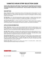
Figure 19<br />
(Typical Pivot Bearing Installation)<br />
View A, Figure 19 depicts a bearing<br />
installed with a press or slip fit. The<br />
outer race is incorporates an integral<br />
machined lip on one side and a swaging<br />
groove on the opposite. As in most<br />
installations of this type, including<br />
spherical bearings, the swaged lip is<br />
primarily for axial retention. It is not<br />
intended to prevent outer race rotation in<br />
the housing. If there is concern about<br />
bearing rotation in the housing, consider<br />
the use of a press fit in addition to the<br />
grooves or an adhesive. Suggested press<br />
fits are presented in this document.<br />
Bearings installed with swaging grooves<br />
can be replaced without damage to the<br />
housing.