Solid State Shortwave Receivers For Beginners - The Listeners Guide
Solid State Shortwave Receivers For Beginners - The Listeners Guide
Solid State Shortwave Receivers For Beginners - The Listeners Guide
Create successful ePaper yourself
Turn your PDF publications into a flip-book with our unique Google optimized e-Paper software.
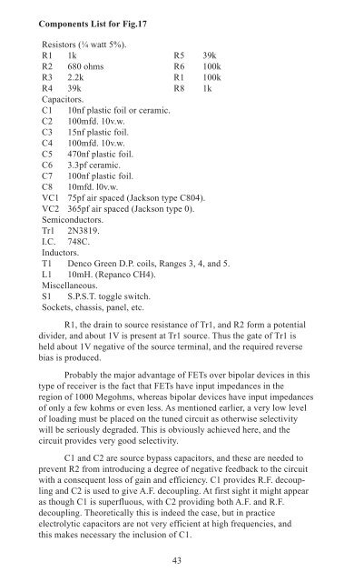
Components List for Fig.17<br />
Resistors (¼ watt 5%).<br />
R1 1k R5 39k<br />
R2 680 ohms R6 100k<br />
R3 2.2k R1 100k<br />
R4 39k R8 1k<br />
Capacitors.<br />
C1 10nf plastic foil or ceramic.<br />
C2 100mfd. 10v.w.<br />
C3 15nf plastic foil.<br />
C4 100mfd. 10v.w.<br />
C5 470nf plastic foil.<br />
C6 3.3pf ceramic.<br />
C7 100nf plastic foil.<br />
C8 10mfd. l0v.w.<br />
VC1 75pf air spaced (Jackson type C804).<br />
VC2 365pf air spaced (Jackson type 0).<br />
Semiconductors.<br />
Tr1 2N3819.<br />
I.C. 748C.<br />
Inductors.<br />
T1 Denco Green D.P. coils, Ranges 3, 4, and 5.<br />
L1 10mH. (Repanco CH4).<br />
Miscellaneous.<br />
S1 S.P.S.T. toggle switch.<br />
Sockets, chassis, panel, etc.<br />
R1, the drain to source resistance of Tr1, and R2 form a potential<br />
divider, and about 1V is present at Tr1 source. Thus the gate of Tr1 is<br />
held about 1V negative of the source terminal, and the required reverse<br />
bias is produced.<br />
Probably the major advantage of FETs over bipolar devices in this<br />
type of receiver is the fact that FETs have input impedances in the<br />
region of 1000 Megohms, whereas bipolar devices have input impedances<br />
of only a few kohms or even less. As mentioned earlier, a very low level<br />
of loading must be placed on the tuned circuit as otherwise selectivity<br />
will be seriously degraded. This is obviously achieved here, and the<br />
circuit provides very good selectivity.<br />
C1 and C2 are source bypass capacitors, and these are needed to<br />
prevent R2 from introducing a degree of negative feedback to the circuit<br />
with a consequent loss of gain and efficiency. C1 provides R.F. decoupling<br />
and C2 is used to give A.F. decoupling. At first sight it might appear<br />
as though C1 is superfluous, with C2 providing both A.F. and R.F.<br />
decoupling. <strong>The</strong>oretically this is indeed the case, but in practice<br />
electrolytic capacitors are not very efficient at high frequencies, and<br />
this makes necessary the inclusion of C1.<br />
43


