Condition Inspection and Analysis of Four, Prominent ... - AREMA
Condition Inspection and Analysis of Four, Prominent ... - AREMA
Condition Inspection and Analysis of Four, Prominent ... - AREMA

You also want an ePaper? Increase the reach of your titles
YUMPU automatically turns print PDFs into web optimized ePapers that Google loves.
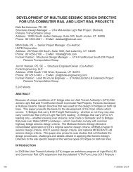
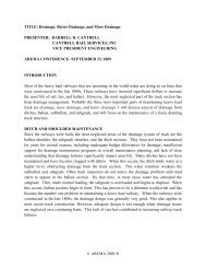
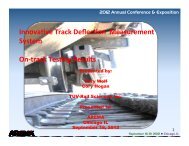
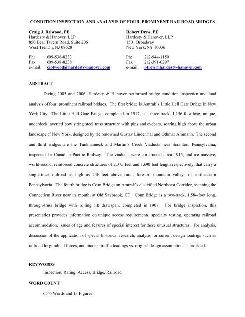
CONDITION INSPECTION AND ANALYSIS OF FOUR, PROMINENT RAILROAD BRIDGES<br />
Craig J. Rolwood, PE Robert Drew, PE<br />
Hardesty & Hanover, LLP Hardesty & Hanover, LLP<br />
850 Bear Tavern Road, Suite 206 1501 Broadway<br />
West Trenton, NJ 08628 New York, NY 10036<br />
Ph: 609-538-8233 Ph: 212-944-1150<br />
Fax 609-538-8238 Fax 212-391-0297<br />
e-mail: crolwood@hardesty-hanover.com e-mail: rdrew@hardesty-hanover.com<br />
ABSTRACT<br />
During 2005 <strong>and</strong> 2006, Hardesty & Hanover performed bridge condition inspection <strong>and</strong> load<br />
analysis <strong>of</strong> four, prominent railroad bridges. The first bridge is Amtrak’s Little Hell Gate Bridge in New<br />
York City. The Little Hell Gate Bridge, completed in 1917, is a three-track, 1,156-foot long, unique,<br />
underdeck inverted bow string steel truss structure with pins <strong>and</strong> eyebars, soaring high above the urban<br />
l<strong>and</strong>scape <strong>of</strong> New York, designed by the renowned Gustav Lindenthal <strong>and</strong> Othmar Ammann. The second<br />
<strong>and</strong> third bridges are the Tunkhannock <strong>and</strong> Martin’s Creek Viaducts near Scranton, Pennsylvania,<br />
inspected for Canadian Pacific Railway. The viaducts were constructed circa 1915, <strong>and</strong> are massive,<br />
world-record, reinforced concrete structures <strong>of</strong> 2,375 feet <strong>and</strong> 1,600 feet length respectively, that carry a<br />
single-track railroad as high as 240 feet above rural, forested mountain valleys <strong>of</strong> northeastern<br />
Pennsylvania. The fourth bridge is Conn Bridge on Amtrak’s electrified Northeast Corridor, spanning the<br />
Connecticut River near its mouth, at Old Saybrook, CT. Conn Bridge is a two-track, 1,584-foot long,<br />
through-truss bridge with rolling lift drawspan, completed in 1907. For bridge inspection, this<br />
presentation provides information on unique access requirements, specialty testing, operating railroad<br />
accommodation, issues <strong>of</strong> age <strong>and</strong> features <strong>of</strong> special interest for these unusual structures. For analysis,<br />
discussion <strong>of</strong> the application <strong>of</strong> special historical research, analysis for current design loadings such as<br />
railroad longitudinal forces, <strong>and</strong> modern traffic loadings vs. original design assumptions is provided.<br />
KEYWORDS<br />
<strong>Inspection</strong>, Rating, Access, Bridge, Railroad<br />
WORD COUNT<br />
6546 Words <strong>and</strong> 13 Figures
Craig Rolwood <strong>and</strong> Robert Drew Page 3<br />
INTRODUCTION<br />
The period between approximately the mid-1890s through World War I in 1917 was a<br />
“golden age” <strong>of</strong> railroad bridge engineering in North America.<br />
Hardesty & Hanover LLP (H&H) had the privilege between mid-2005 <strong>and</strong> mid-2006 to<br />
inspect four, prominent railroad structures that date to the first 20 years <strong>of</strong> the 20 th Century. The<br />
bridges are as follows, presented in the order that these were inspected by H&H:<br />
• Little Hell Gate Bridge in New York NY, owned by Amtrak<br />
• Tunkhannock Viaduct in Nicholson PA, owned by Canadian Pacific Railway<br />
• Martin’s Creek Viaduct near Kingsley PA, owned by Canadian Pacific Railway<br />
• Connecticut River Bridge in Old Saybrook CT, owned by Amtrak<br />
In addition to inspection, three <strong>of</strong> four <strong>of</strong> the structures were completely analyzed for<br />
load rating capacity (seismic excluded). Specialized ultrasonic pin testing <strong>and</strong> concrete testing<br />
were performed.<br />
This paper presents some <strong>of</strong> the unique challenges that these bridges provided, <strong>and</strong><br />
solutions <strong>of</strong>fered, in the areas <strong>of</strong><br />
Little Hell Gate Bridge<br />
• Field inspection access<br />
• Specialty Testing<br />
• Load rating analysis<br />
The Little Hell Gate Bridge was designed by the famous bridge engineer, Othmar<br />
Ammann, as part <strong>of</strong> the New York Extension <strong>of</strong> the Pennsylvania Railroad. While the Little Hell<br />
Gate Bridge is a significant structure in its own right, it is overshadowed by its nearby sibling<br />
structure, the famous Hell Gate Bridge through-arch bridge, designed by Ammann’s boss on the
Craig Rolwood <strong>and</strong> Robert Drew Page 4<br />
project, the renowned bridge engineer, Gustav Lindenthall. The Little Hell Gate bridge<br />
construction was completed in 1917, <strong>and</strong> has carried passenger <strong>and</strong> freight trains since.<br />
The Little Hell Gate Bridge (See Figure 1) is a<br />
four span, inverted bowstring truss bridge over the<br />
former Little Hell Gate between R<strong>and</strong>all’s <strong>and</strong> Ward’s<br />
Isl<strong>and</strong>s. The structure was originally designed to carry<br />
four tracks, but the southernmost set has been taken<br />
out <strong>of</strong> service <strong>and</strong> removed. The bridge carries both<br />
eastbound <strong>and</strong> westbound trains between Boston <strong>and</strong><br />
Penn Station. In its history, the Little Hell Gate Bridge has seen little maintenance or<br />
rehabilitation. Since its construction, the bridge has been painted twice (in 1939 <strong>and</strong> 1995) <strong>and</strong> a<br />
rehabilitation contract was performed in 1992 for minor steel repairs.<br />
Approximately 20 years after the bridge was constructed, the Little Hell Gate waterway<br />
below was filled in with construction excavations <strong>and</strong> debris during the 1930s construction <strong>of</strong> the<br />
Triborough Bridges. R<strong>and</strong>all’s <strong>and</strong> Ward’s Isl<strong>and</strong>s are now a single l<strong>and</strong> mass bordered by the<br />
East River to the west, the Bronx Kill to the east <strong>and</strong> the Hell Gate to the south. The area directly<br />
to the east (south) <strong>of</strong> the bridge currently houses a sewage treatment plant <strong>and</strong> the New York City<br />
Fire Academy. Directly to the west (north) <strong>of</strong> the Little Hell Gate Bridge are the approach spans<br />
<strong>of</strong> the Triborough Bridge, local access roadways, waste areas <strong>and</strong> parkl<strong>and</strong>.<br />
Tunkhannock <strong>and</strong> Martin’s Creek Viaducts<br />
Figure 1. End Span <strong>of</strong><br />
Amtrak Little Hell Gate Bridge<br />
The Tunkhannock Viaduct (Bridge 653.22 Freight Main Line – See Figure 2) is a twelve<br />
span reinforced concrete arch bridge that, at the time <strong>of</strong> its completion in 1915, was the largest<br />
concrete bridge in the world. The structure was designed by Abraham Burton Cohen <strong>and</strong><br />
constructed by the Delaware, Lackawanna <strong>and</strong> Western Railroad as part <strong>of</strong> the ‘Hallstead Cut<strong>of</strong>f’.
Craig Rolwood <strong>and</strong> Robert Drew Page 5<br />
Tunkhannock (also known as the Nicholson Viaduct) was constructed in order to eliminate the<br />
difficult grade changes that the railroad encountered along its original path on what is now<br />
Pennsylvania Route 11. The construction <strong>of</strong> the bridge also shortened the travel distance <strong>of</strong> trains<br />
between New Milford <strong>and</strong> Clarks Summit by three <strong>and</strong> a half miles. It was originally designed to<br />
carry two tracks, but today carries only one along its eastern side that services both northbound<br />
<strong>and</strong> southbound freight trains from Binghamton NY<br />
(North) to Scranton PA (South). The bridge stretches<br />
2,375 feet across the rural valley over which it is sited,<br />
<strong>and</strong> soars 240 feet above the east branch <strong>of</strong><br />
Tunkhannock Creek at its highest point. The<br />
Tunkhannock Viaduct is a designated historic, civil<br />
engineering l<strong>and</strong>mark <strong>of</strong> the American Society <strong>of</strong> Civil<br />
Engineers.<br />
The structure has ten visible spans, each measuring 180 feet in length, <strong>and</strong> is flanked by<br />
two abutment spans that were buried during construction. Each <strong>of</strong> the piers is founded on<br />
bedrock, which at the time <strong>of</strong> construction was up to 138 feet below grade. Nearly half <strong>of</strong> the<br />
structure’s mass is buried underground.<br />
Figure 3: Tunkhannock Viaduct<br />
Roadway<br />
Figure 2: Canadian Pacific Railway<br />
Tunkhannock Viaduct<br />
As previously noted, a single track operates on<br />
the bridge at present <strong>and</strong> carries only freight trains<br />
(See Figure 3). There are reportedly an average <strong>of</strong> ten<br />
freight trains per day carried on the line at present.<br />
The closed western track line area now serves as an<br />
access road along the full length <strong>of</strong> the bridge. The<br />
track is supported on timber ties that rest in a ballast
Craig Rolwood <strong>and</strong> Robert Drew Page 6<br />
<strong>and</strong> gravel bed. The ballast is supported by a reinforced concrete bridge deck, which was<br />
constructed with an applied waterpro<strong>of</strong>ing system. Three-foot thick reinforced concrete parapets<br />
extend the length <strong>of</strong> the bridge along each fascia. At the visible spans, the concrete deck was<br />
poured atop reinforced concrete sp<strong>and</strong>rel arches, which are then supported by reinforced concrete<br />
sp<strong>and</strong>rel walls. In each span, there are twelve sp<strong>and</strong>rel walls, ten <strong>of</strong> which are supported on the<br />
arch ribs themselves. The two end walls comprise a portion <strong>of</strong> the tower at each support pier.<br />
The sp<strong>and</strong>rel walls apportion the span into eleven equal-length panels. The main structural<br />
elements <strong>of</strong> each span are the east <strong>and</strong> west reinforced concrete arch ribs (the sp<strong>and</strong>rel walls<br />
separate in an archway at varied elevations above the ribs) that spring from each pier 125 feet<br />
below the top <strong>of</strong> deck.<br />
Figure 4: Canadian Pacific Railway<br />
Martin’s Creek Viaduct<br />
The Martin’s Creek Viaduct (Bridge 644.25<br />
Freight Main Line – See Figure 4) is a ten span<br />
reinforced concrete arch bridge, built in conjunction<br />
with the Tunkhannock Viaduct (nine miles distant) as<br />
part <strong>of</strong> the “Hallstead Cut<strong>of</strong>f” project. The Martin’s<br />
Creek Viaduct is 1600 feet long with 150-foot high<br />
arches. The structure was completed in 1914 <strong>and</strong> was<br />
originally constructed with three tracks. Today it<br />
carries a single center track, which services both northbound <strong>and</strong> southbound trains on the rail<br />
line.<br />
The geometric makeup <strong>of</strong> the bridge varies for the first three spans. Spans 1 <strong>and</strong> 2 are<br />
short single arch spans that directly support the railway deck. Spans 3 through 10 are similar to<br />
the visible spans <strong>of</strong> the Tunkhannock Viaduct. Each span consists <strong>of</strong> two arch ribs that support a<br />
series <strong>of</strong> sp<strong>and</strong>rel walls, which in turn support the sp<strong>and</strong>rel arches <strong>and</strong> deck above. Reinforced
Craig Rolwood <strong>and</strong> Robert Drew Page 7<br />
concrete parapets extend the length <strong>of</strong> the bridge along each fascia. Span 3 is shorter than Spans<br />
4 through 10; the span supports seven sp<strong>and</strong>rel walls, five <strong>of</strong> which rest directly on the arch ribs.<br />
Spans 4 through 10 each support eleven sp<strong>and</strong>rel walls, nine <strong>of</strong> which rest directly on the arch<br />
ribs. The two end walls comprise a portion <strong>of</strong> the tower at each support pier. The ten piers<br />
supporting the structure are buried deep below grade. The north abutment span similarly consists<br />
<strong>of</strong> two reinforced concrete arch ribs supporting four sp<strong>and</strong>rel walls, which in turn support the<br />
deck above. Concrete sidewalls block in the span along the east <strong>and</strong> west fasciae; a significant<br />
portion <strong>of</strong> the north abutment span is buried under fill material.<br />
Connecticut River Bridge<br />
The 100-year-old Connecticut River Bridge is<br />
part <strong>of</strong> the rail infrastructure that has served New<br />
Engl<strong>and</strong> for many years (See Figure 5). CONN bridge<br />
is one <strong>of</strong> nine movable railroad bridges along the<br />
Connecticut coast main passenger line between<br />
Stamford in the west <strong>and</strong> Mystic in the east. The<br />
existing bridge, constructed circa 1907, is a two-track,<br />
Figure 5. Amtrak Connecticut River<br />
Bridge<br />
open deck, electrified railroad bridge, 1564 feet long, consisting <strong>of</strong> seven thru-truss spans, two<br />
deck girder spans, <strong>and</strong> one 158-ft Scherzer-type Rolling Lift span. The bridge carries<br />
approximately 35 passenger <strong>and</strong> six freight trains per weekday. In recent years, the draw span <strong>of</strong><br />
the bridge has experienced approximately 3700 yearly openings to accommodate navigation on<br />
the Connecticut River. The bridge spans the Connecticut River near its mouth at Navigation MP<br />
3.4 in the towns <strong>of</strong> Old Saybrook <strong>and</strong> Old Lyme, CT. The approach span structures were<br />
designed by the New York, New Haven <strong>and</strong> Hartford Railroad (N.Y.N.H. & H.R.R.); the bascule<br />
span was designed for the N.Y.N.H. & H.R.R. by the Scherzer Rolling Lift Bridge Company in
Craig Rolwood <strong>and</strong> Robert Drew Page 8<br />
1905. The structure was constructed by American Bridge Company beginning in 1906. The<br />
structure is used primarily for passenger trains for the AMTRAK Northeast Corridor with one or<br />
more daily round trips for the Providence <strong>and</strong> Wooster (P&W) freight train <strong>and</strong> the occasional<br />
maintenance rail cars.<br />
INSPECTION ACCESS<br />
The inspection <strong>of</strong> these four, prominent railroad bridges required addressing many <strong>of</strong> the<br />
typical challenges <strong>of</strong> major bridge inspection, but also provided some unique challenges. In<br />
addition to a brief discussion <strong>of</strong> some <strong>of</strong> the st<strong>and</strong>ard railroad bridge inspection issues, some <strong>of</strong><br />
the unique inspection access challenges are also presented here, with an account <strong>of</strong> how these<br />
challenges were met in the field.<br />
Major Railroad Bridge <strong>Inspection</strong> Typical Issues<br />
Some typical issues that must be addressed for performing inspection <strong>of</strong> existing railroad<br />
bridges include these that were addressed as part <strong>of</strong> the work on these projects.<br />
Field Safety<br />
• Safety against falls, as detailed further below.<br />
• Proper inspection scope: What level <strong>of</strong> detail is time <strong>and</strong> cost effective?<br />
• Proper testing scope: how much <strong>and</strong> what type <strong>of</strong> specialty testing is appropriate?<br />
• Site Specific Work Plans – plan in detail field activities for efficiency <strong>and</strong> safety.<br />
Federal Railroad Administration 49 CFR 214.103 Subpart B, “Bridge Worker Safety<br />
St<strong>and</strong>ards” regulates minimum safety st<strong>and</strong>ards on bridges where fall hazards may exist.<br />
Hardesty & Hanover has also developed some simple <strong>and</strong> practical safety rules for performance<br />
<strong>of</strong> bridge condition inspections follows:
Craig Rolwood <strong>and</strong> Robert Drew Page 9<br />
“While performing condition inspection <strong>of</strong> railroad bridges at 12 feet or more above the<br />
ground, <strong>and</strong> for bridges above water more than four feet deep, employees shall comply with the<br />
following:<br />
1. Employees shall not perform inspections alone, but shall work in groups <strong>of</strong> two<br />
or more.<br />
2. The employee shall not climb steel unaided by equipment, except where<br />
specifically <strong>and</strong> formally trained in safe climbing techniques.<br />
3. When walking on the bridge, employees shall perform inspection work, to the<br />
greatest extent possible, from maintenance access walks, from behind safety<br />
railings, <strong>and</strong> from areas between the outside rails <strong>of</strong> the track, in which areas<br />
federal regulations do not require special fall protection.<br />
4. Where access to heights is required, the employee shall use approved access<br />
equipment that has been properly placed <strong>and</strong> secured for inspection use.<br />
Examples <strong>of</strong> equipment include bucket trucks, underbridge inspection units, lift<br />
trucks <strong>and</strong> scaffolding.<br />
5. Where used, ladders shall be founded on solid ground, in areas safe from<br />
vehicular impact, to access relatively low heights only. One person shall remain<br />
at the base <strong>of</strong> the ladder <strong>and</strong> hold the ladder stiles while the inspector uses the<br />
ladder.<br />
6. If any employee does not underst<strong>and</strong> the site safety provisions for inspection, or<br />
feels that conditions are unsafe, the employee shall notify the field supervisor <strong>of</strong><br />
their concerns, <strong>and</strong> is not required to perform field inspection work until that<br />
employee underst<strong>and</strong>s the safety provisions <strong>and</strong>/or has been provided reasonable<br />
demonstration that safe conditions are provided.”
Craig Rolwood <strong>and</strong> Robert Drew Page 10<br />
Another area <strong>of</strong> special field safety that sometimes needs to be addressed is the area <strong>of</strong><br />
confined spaces per OSHA regulations.<br />
Bridge <strong>Inspection</strong> Unique Project Access Issues<br />
Several atypical issues arose which needed to be addressed as part <strong>of</strong> the inspection work<br />
for these projects. Some <strong>of</strong> these problems encountered, <strong>and</strong> solutions <strong>of</strong>fered, are briefly<br />
presented here.<br />
Martin’s Creek Viaduct Access Road Deterioration<br />
At Martin’s Creek Viaduct, during inspection the field crew found that the<br />
railroad right-<strong>of</strong>-way access road to the site had been severely rutted during the winter<br />
<strong>and</strong> early spring due to recent, heavy rains, such that the inspection equipment could not<br />
gain access to the bridge. The remote <strong>and</strong> mountainous terrain prohibited alternate access<br />
means. CP Railway crews were not available to respond to the situation, because <strong>of</strong><br />
emergent conditions on other railway bridges within the territory, also caused by the<br />
recent heavy rains <strong>and</strong> severe flooding in the Susquehanna River valley. This situation<br />
threatened costly delays to the project.<br />
The Hardesty & Hanover inspection team leader at the site was experienced with<br />
operation <strong>of</strong> small construction equipment. Without delay, the inspector rented a small<br />
bulldozer for the day, performed the necessary grading work <strong>of</strong> the access road (all work<br />
was outside the limits <strong>of</strong> the FRA fouling envelope for the active tracks). After the<br />
minor but necessary roadway repair work was done, the inspection team accessed the<br />
site, <strong>and</strong> the inspection team leader informed the home <strong>of</strong>fice <strong>of</strong> the completed work.
Craig Rolwood <strong>and</strong> Robert Drew Page 11<br />
Connecticut River Bridge High Voltage Railroad Electrification Facilities<br />
H<strong>and</strong>s-on inspection <strong>of</strong> the Connecticut River Bridge included working around<br />
25,000 Volt railroad electrification wires <strong>and</strong> feed lines. Safety rules require that<br />
inspectors maintain 15 feet clear distance to live wires. In 2000, electrification was<br />
added to the bridge. The high-voltage,<br />
negative feed lines <strong>of</strong> the system were<br />
mounted on the outboard faces <strong>of</strong> the through<br />
trusses, just below the level <strong>of</strong> the upper<br />
chord. This combined with the catenary<br />
system mounted immediately above each <strong>of</strong><br />
the two tracks, prevented inspection access to<br />
the entire top half <strong>of</strong> the trusses while the<br />
electrification system was live, <strong>and</strong> the h<strong>and</strong>s-<br />
on inspection work could only be performed while at least one track was out <strong>of</strong> service,<br />
<strong>and</strong> the electrification system for that track de-energized <strong>and</strong> grounded.<br />
Night work would be a possibility for work requiring taking a track out <strong>of</strong> service<br />
with the electrification system de-energized; however, inspecting a structure at night,<br />
even with expensive floodlights, is not usually effective.<br />
The field team was able to arrange with Amtrak to piggy-back the inspection<br />
with planned, 55-hour weekend single track outages being made for other construction<br />
activity. This weekend work permitted h<strong>and</strong>s-on inspection <strong>of</strong> the upper portions <strong>of</strong> the<br />
truss work during daylight hours.<br />
Figure 6: Complex Electrification<br />
Movable Catenary Unit, Retracted to<br />
Permit Drawspan Rear to Open
Craig Rolwood <strong>and</strong> Robert Drew Page 12<br />
Connecticut River Bridge Security Notification<br />
For bridges in navigable waterways, security clearance <strong>of</strong> employees is required,<br />
which means that the US Coast Guard needs to be notified, <strong>and</strong> the social security<br />
numbers <strong>of</strong> each employee proposed to work at the bridge needs to be provided. The use<br />
<strong>of</strong> Social Security Numbers presents some privacy concerns. It is hoped that a simple<br />
system such as the rail security registration systems that some railroads are adopting for<br />
contract employees working on their right-<strong>of</strong>-way may be adopted for more universal<br />
use, to include work at bridges over navigable waterways.<br />
In order to inspect the underside <strong>of</strong> the bridge <strong>and</strong> to provide as little interference<br />
with rail operations as possible, the inspection work was performed using a manlift on a<br />
barge. The barge was propelled by a push-tug. A safety <strong>and</strong> inspection powerboat was<br />
also provided.<br />
Work in the navigable channel <strong>of</strong> the Connecticut River was coordinated with<br />
river traffic. During the summer months, the Connecticut River has constant recreational<br />
boating.<br />
Tunkhannock <strong>and</strong> Martin’s Creek Extreme Height<br />
The viaducts have a height <strong>of</strong> up to 240 feet<br />
above the valley floor. The inspection plan required<br />
coordinating a variety <strong>of</strong> access equipment to effectively<br />
access portions <strong>of</strong> the structure for h<strong>and</strong>s-on inspection.<br />
• As a safety measure, the local fire <strong>and</strong><br />
rescue departments were notified prior<br />
to the inspection <strong>of</strong> the work being Figure 7: UBIU-60 at<br />
Tunkhannock Viaduct
Craig Rolwood <strong>and</strong> Robert Drew Page 13<br />
performed, so that they might be prepared in the unlikely event <strong>of</strong> the<br />
need for emergency rescue.<br />
• To access the lowest portions <strong>of</strong> the structures, a 135-foot manlift was<br />
used where ground access permitted.<br />
• To access the upper portions <strong>of</strong> the structure, an Underbridge <strong>Inspection</strong><br />
Unit (UBIU) with a 60-foot reach was used (See Figure 7). Rail-<br />
mounted units are available; however, where an access road is available,<br />
using road-based vehicles is vastly preferable, to avoid scheduling <strong>and</strong><br />
other access issues with track time. Track time availability was very<br />
limited for our use at Tunkhannock <strong>and</strong> Martin’s Creek Viaducts.<br />
• To access the mid-height<br />
portions <strong>of</strong> the structure, a<br />
spider basket attached to a<br />
truck-mounted crane was used<br />
(See Figure 8).<br />
• Safe climbing using harnesses<br />
was also employed, along the<br />
top <strong>and</strong> center <strong>of</strong> the arches where the edge falling hazard was more than<br />
one body-length distant (See Figure 9).<br />
Figure 8: Spider Basket <strong>Inspection</strong><br />
The detailed, site-specific work inspection plan was particularly important for<br />
efficiently coordinating the use <strong>of</strong> crews <strong>and</strong> equipment at these two structures. The<br />
comprehensive inspection <strong>of</strong> these massive, concrete structures was accomplished in just<br />
a few weeks time. Due to the difficulty in accessing some areas from the top <strong>of</strong> deck or<br />
from ground level (a result <strong>of</strong> structure size, site topography <strong>and</strong> obstructions), it was
Craig Rolwood <strong>and</strong> Robert Drew Page 14<br />
determined to be economically unfeasible to<br />
inspect every surface <strong>of</strong> the structure “h<strong>and</strong>s-<br />
on”. The best use <strong>of</strong> inspection resources<br />
within the allotted schedule was to perform a<br />
complete <strong>and</strong> thorough visual inspection <strong>of</strong> the<br />
structures using reasonable access methods,<br />
<strong>and</strong> then to focus on close-up inspection <strong>of</strong> a<br />
representative span at each structure, <strong>and</strong> to extrapolate this inspection data to other<br />
spans. By following this methodology, the inspection teams focused more on the<br />
behavior <strong>of</strong> the structure <strong>and</strong> on overall rehabilitation needs. The similarities in<br />
deterioration conditions <strong>and</strong> locations throughout the structure were noted.<br />
Movable Bridge Facilities<br />
The Connecticut River Bridge includes a 100-year-old, rolling lift bascule draw span.<br />
<strong>Inspection</strong> <strong>of</strong> the electrical <strong>and</strong> mechanical facilities <strong>of</strong> these bridges requires trained individuals<br />
who are knowledgeable in <strong>and</strong> experienced with:<br />
SPECIAL TESTING<br />
• movable bridge technology <strong>and</strong> practices,<br />
• railroad operations environment,<br />
• interaction <strong>of</strong> structural-mechanical-electrical systems <strong>of</strong> the movable bridge,<br />
• signaling interface with the electrical operating system, <strong>and</strong><br />
• electrification interface with the bridge drawspan operations.<br />
There are a few basic questions to ask when considering the need for specialized<br />
materials or other testing:<br />
Figure 9: Tunkhannock Viaduct, Arch<br />
Topside Access
Craig Rolwood <strong>and</strong> Robert Drew Page 15<br />
• What is the value to the railroad <strong>of</strong> testing for the time <strong>and</strong> money expended?<br />
• How will the anticipated results be used?<br />
• How much testing is needed?<br />
• Is the inspection phase the right time to take tests, or is it better done as part <strong>of</strong><br />
detailed design development, or even during construction?<br />
For three <strong>of</strong> the four bridges on this project, specialty testing was undertaken. For the<br />
Tunkhannock <strong>and</strong> Martin’s Creek Viaducts, limited concrete coring <strong>and</strong> laboratory examination<br />
were undertaken, partly to confirm suppositions made from visual observations <strong>and</strong> partly to<br />
confirm results from previous testing performed on the viaducts. At Little Hell Gate Bridge, all<br />
78 truss joint pins were ultrasonically tested for hidden flaws. At Connecticut River Bridge,<br />
specialty testing was not performed as part <strong>of</strong> the 2006 inspection. Extensive pin testing had been<br />
performed at the Connecticut River Bridge for the previous, in-depth inspection, at which time no<br />
immediately worrisome conditions had been found. Rehabilitation work on the mechanical <strong>and</strong><br />
electrical systems <strong>of</strong> the bridge had also just recently been completed, so that new, specialized<br />
movable bridge testing was not warranted.<br />
Challenge for Ultrasonic Pin Testing at Little Hell Gate Bridge<br />
Figure 10: Pin Cap Removal <strong>and</strong><br />
Testing at Little Hell Gate<br />
The main challenge for testing <strong>of</strong> the pins at the<br />
Little Hell Gate Bridge was not testing the pins. It was<br />
accessing the face <strong>of</strong> the pins (See Figure 10).<br />
For nearly 90 years, the pins at Little Hell Gate<br />
Bridge had been retained <strong>and</strong> protected by cast iron caps.<br />
Temporarily removing these caps for access to the faces<br />
proved much more difficult than anticipated. It was
Craig Rolwood <strong>and</strong> Robert Drew Page 16<br />
initially planned that the access equipment supplier would remove the caps as part <strong>of</strong> their scope.<br />
The supplier could not remove the rust-frozen bolts that retained the caps.<br />
The solution was to hire a small, ironwork contractor, who employed a specialized,<br />
hydraulic torque wrench to loosen the through bolts, remove the caps, <strong>and</strong> then reinstall the caps<br />
<strong>and</strong> bolts. After breaking the first bolt head while<br />
trying to figure out how to do the work, the contractor<br />
was able subsequently to successfully remove <strong>and</strong><br />
reinstall the remainder <strong>of</strong> the caps (See Figure 11).<br />
Through very tight scheduling <strong>and</strong> coordination <strong>of</strong> the<br />
access equipment usage, the ironwork contractor <strong>and</strong><br />
the testing technician, budget <strong>and</strong> schedule were<br />
maintained.<br />
Concrete Testing at Tunkhannock <strong>and</strong> Martin’s Creek Viaducts<br />
Limited concrete investigations were performed for the viaducts, the overall purpose<br />
being to sample the concrete to check compressive strength against rating analysis assumptions,<br />
<strong>and</strong> to verify some <strong>of</strong> the mechanisms causing deterioration for estimating the repair quantities<br />
<strong>and</strong> costs. After initial examination <strong>of</strong> core samples indicated evidences <strong>of</strong> Alkali-Silica<br />
Reactivity (ASR), petrographic analysis was performed on two <strong>of</strong> the core samples to check the<br />
extent <strong>and</strong> the activity <strong>of</strong> the ASR. It was found that the concrete, while having suffered the<br />
effects <strong>of</strong> freeze-thaw <strong>and</strong> ASR, was generally in a stable state. It was recommended that a<br />
rehabilitation that addresses the visually observed areas <strong>of</strong> surface deterioration would likely<br />
suffice to repair the structure for continuous, acceptable service.<br />
Figure 11: Pin Cap Removed
Craig Rolwood <strong>and</strong> Robert Drew Page 17<br />
LOAD RATINGS AND HISTORICAL RESEARCH<br />
Included in the scope <strong>of</strong> work for three <strong>of</strong> the four bridges, was a comprehensive live<br />
load capacity rating <strong>of</strong> the structures. For the fourth structure, the Connecticut River Bridge,<br />
rating effort was limited to checking as-inspected rating capacities for any areas where member<br />
deterioration had advanced since the previous comprehensive inspection <strong>of</strong> nearly ten years<br />
earlier.<br />
For these major bridges designed during the early years <strong>of</strong> the 20 th century, underst<strong>and</strong>ing<br />
the load rating analyses <strong>of</strong> the bridge members today, required research into the original<br />
assumptions <strong>of</strong> the designers. Because <strong>of</strong> the prominence <strong>of</strong> the bridges, published information<br />
from transaction papers was available to unlock a few mysteries during initial load rating analyses<br />
<strong>of</strong> the structures.<br />
Major Railroad Bridge Load Rating Typical Issues<br />
Some typical issues that must be addressed for performing load rating analysis <strong>of</strong> existing<br />
railroad bridges include these that were addressed as part <strong>of</strong> the work on these projects.<br />
1. Fatigue analysis <strong>of</strong> steel tension members per <strong>AREMA</strong> 15-7.3.4.2.<br />
2. Longitudinal forces per current design codes versus allowances in older codes<br />
<strong>and</strong> actual forces anticipated per local operations<br />
3. Acceptance criteria <strong>and</strong> current operating equipment, for both normal <strong>and</strong><br />
maximum live load rating conditions<br />
Load Rating Unique Projects Issues<br />
Several atypical issues arose which needed to be addressed as part <strong>of</strong> the load rating<br />
analysis for these projects. Some <strong>of</strong> these problems encountered, <strong>and</strong> solutions <strong>of</strong>fered, <strong>and</strong> here<br />
briefly presented.
Craig Rolwood <strong>and</strong> Robert Drew Page 18<br />
Little Hell Gate Bridge Variable Allowable Stresses<br />
An unusual result occurred from our initial load <strong>and</strong> capacity analysis <strong>of</strong> the<br />
Little Hell Gate Bridge, <strong>and</strong> detailed research provided an interesting explanation.<br />
For “Normal Rating” per <strong>AREMA</strong> Chapter 15 Section 7.3, all structural<br />
members were found to have capacity in excess <strong>of</strong> Cooper E-60, except for a few<br />
members that were found to have a calculated rating capacity <strong>of</strong> slightly less than the<br />
basic acceptance criteria <strong>of</strong> Cooper E-60, between E-57 <strong>and</strong> E-59.<br />
An investigation was made as to why these members would rate less than what<br />
the bridge was originally designed for, namely Cooper E-60 live load. This was<br />
especially puzzling, since the original design drawings specifically stated that two full<br />
tracks <strong>of</strong> load are applied per truss, as compared to a computed maximum 1.6875 tracks<br />
tributary to the trusses for current conditions <strong>and</strong> design st<strong>and</strong>ards. Also, the original<br />
design would have likely included higher, steam impact. So why would the bridge rate<br />
less than E-60, especially with lighter, current design loadings?<br />
In researching the possible reason for these lower than anticipated initial ratings,<br />
the answer was found in an ASCE transaction paper that had been written by designer<br />
Othmar Ammann 1 . Ammann stated that unit stresses used for steel materials were taken<br />
as “from five eighths to three fourths <strong>of</strong> the minimum elastic limit”; i.e., 0.625 Fy to 0.75<br />
Fy. Normal rating per <strong>AREMA</strong> Chapter 15 is based upon 0.55 Fy, <strong>and</strong> this is sufficient<br />
to explain the less-than E-60 capacity <strong>of</strong> the low-rating members. Increasing the<br />
allowable stress for normal rating to an amount very little above 0.55 Fy will increase the<br />
rating capacity from E-57 to above E-60.<br />
1 Ammann, Othmar, ASCE Transactions Vol. LXXII, Paper No. 1417 presented Nov. 21, 1917
Craig Rolwood <strong>and</strong> Robert Drew Page 19<br />
Little Hell Gate Bridge Eyebar Allowable Stresses<br />
For pin-connected members, allowable tension stress is K = 0.45 Fy, per<br />
<strong>AREMA</strong> Section 15-1.4 2004 update, Table 15-1-11. In Table 3-11 <strong>of</strong> the 1994 update,<br />
no special provision for pin-connected truss members was indicated. The 2004<br />
commentary for this section references a single, 1939 ASCE transaction paper as the<br />
source for the more conservative allowable stress applied to pin-connected members. We<br />
obtained a copy <strong>of</strong> the paper, <strong>and</strong> found that forged eye bars are specifically excluded<br />
from the investigation, as stated in the first paragraph <strong>of</strong> the paper: “The present<br />
investigation is concerned with pin-connected plates which do not have reduced width in<br />
the body as is the case <strong>of</strong> the forged eye-bar…” Therefore, basic allowable stress for the<br />
pin-connected, eye-bars at Little Hell Gate were assumed the same as for other tension<br />
members, or 0.55Fy.<br />
Tunkhannock <strong>and</strong> Martin’s Creek Viaducts Original Design Loading Assumptions<br />
The Tunkhannock <strong>and</strong> Martin’s Creek Viaducts are composed <strong>of</strong> Portl<strong>and</strong><br />
Cement concrete, with steel reinforcement. However, the design for the structures is not<br />
based upon modern reinforced concrete principles, but rather on unreinforced masonry<br />
design practices <strong>of</strong> the 19 th century, using mass concrete in place <strong>of</strong> stone masonry.<br />
Additionally, loading conditions used for the original design differ from current <strong>AREMA</strong><br />
recommendations.<br />
For Live Loads <strong>and</strong> Impact Loads for Tunkhannock Viaduct, the 1911 stress<br />
sheets show a non-Cooper series <strong>of</strong> locomotive wheel concentrations (See Figure 12).<br />
The wheel concentrations were positioned on the spans to produce the maximum<br />
stresses in the arch rib for two live load cases, namely, 1) Live load plus impact applied<br />
to the full span length, <strong>and</strong> 2) Live load plus impact applied to one half the span length.
Craig Rolwood <strong>and</strong> Robert Drew Page 20<br />
Figure 12: Present Day Cooper E80 Live Load arrangement compared to<br />
1911 Delaware <strong>and</strong> Lackawanna Railroad Live Load<br />
The original stress sheets apply the live load to the arch rib as concentrated loads<br />
at the sp<strong>and</strong>rel columns. Since the concentrated loads are proportional to the spacing <strong>of</strong><br />
the sp<strong>and</strong>rel columns rather than the magnitude <strong>and</strong> location <strong>of</strong> the wheel concentrations,<br />
it is apparent that an equivalent uniform live load was used as part <strong>of</strong> the original design.<br />
It appears that the original stress sheets calculated the concentrated loads at the sp<strong>and</strong>rel<br />
columns as follows:<br />
1. Locomotive axle loads were positioned on the span for maximum stress<br />
at the arch rib.<br />
2. Once positioned, the concentrated loads were summed <strong>and</strong> divided by<br />
the loaded length to generate a uniform load.<br />
3. A distribution factor was applied to the live load.<br />
4. The live loads were then divided by the width <strong>of</strong> the arch rib to generate<br />
an equivalent uniform load per unit width <strong>of</strong> arch rib.
Craig Rolwood <strong>and</strong> Robert Drew Page 21<br />
5. The concentrated loads at the sp<strong>and</strong>rel columns were then determined by<br />
calculating the reactions <strong>of</strong> the equivalent uniform live load, considering<br />
the tributary area to be one half <strong>of</strong> adjacent concrete deck span lengths.<br />
From review <strong>of</strong> the concentrated live loads tabulated in the stress sheets <strong>and</strong><br />
working backwards using the above procedure uniform track loads were derived.<br />
Similar to live load, a separate impact force was calculated for each sp<strong>and</strong>rel wall<br />
location <strong>and</strong> applied to the main arch rib as a concentrated load. The 1911 stress sheets<br />
show that impact was calculated per the Impact Formula: I = LL 2 / (LL + DL), where I =<br />
Impact Load, LL = Live Load <strong>and</strong> DL = Dead Load. The magnitude <strong>of</strong> the impact force<br />
is a function <strong>of</strong> the ratio <strong>of</strong> live load to dead load. Therefore, the impact at each sp<strong>and</strong>rel<br />
walls varies, impact being greatest at the crown <strong>and</strong> lowest near the skewbacks. As a<br />
percentage <strong>of</strong> live load, the 1911 design impacts are roughly equivalent to 2006 <strong>AREMA</strong><br />
diesel impact per <strong>AREMA</strong> 8.2.2.3.<br />
1911 Temperature Loads for Tunkhannock Viaduct: Temperature loads are<br />
calculated on the 1911 stress sheets based on a temperature rise <strong>of</strong> 30° F <strong>and</strong> a<br />
temperature fall <strong>of</strong> 30° F.<br />
1911 Load Combinations were:<br />
• Dead Load + Temperature<br />
• Live Load + Impact on half the arch span + Dead Load + Temperature<br />
• Live Load + Impact on full arch span + Dead Load + Temperature.<br />
No other loads or combinations were used in the original design.<br />
Tunkhannock Viaduct 1911 Construction Method<br />
The main arch ribs were constructed by the alternate block or voussoir method.<br />
With this method, the arch rib is constructed in transverse blocks <strong>of</strong> such size that each
Craig Rolwood <strong>and</strong> Robert Drew Page 22<br />
block can be completed at one pouring, or<br />
within about a day’s work. The blocks are<br />
poured in such an order as to give a uniform<br />
deflection <strong>of</strong> the centering, <strong>and</strong> also prevent the<br />
crown <strong>of</strong> the arch from rising as the lower arch<br />
loads are placed. This method has the<br />
advantage <strong>of</strong> reducing shrinkage stresses in the<br />
arch ring to a minimum (See Figure 13).<br />
Steel centering was employed in the<br />
construction <strong>of</strong> the Tunkhannock viaduct.<br />
From 1918 “Concrete Engineers H<strong>and</strong>book” by<br />
Hool <strong>and</strong> Johnson, the use <strong>of</strong> three hinged steel<br />
centering had the following advantages:<br />
• Crown deflection using steel centers is usually much less than that<br />
obtained by employing timber falsework.<br />
• It is possible to compute the deflection <strong>of</strong> each point <strong>of</strong> a steel center<br />
with some degree <strong>of</strong> accuracy while, in the case <strong>of</strong> a wooden center, the<br />
probable settlement at each bent is much less definitive.<br />
• The advantage <strong>of</strong> allowing the deflection to be quite accurately computed<br />
makes it possible to give the centers a preliminary camber so that when<br />
the concrete is in place <strong>and</strong> the centering withdrawn, the arch ring will<br />
assume its true position.<br />
Figure 13: Original Design Drawing<br />
Construction Method
Craig Rolwood <strong>and</strong> Robert Drew Page 23<br />
• The unique feature in the steel centering used in constructing the<br />
Tunkhannock Viaduct was an adjustable panel at the crown <strong>of</strong> the steel<br />
arch trusses.<br />
The above information on construction method is important to the proposed load<br />
rating analysis methods for the following reasons:<br />
• The alternate block method <strong>of</strong> construction tells us that concrete<br />
shrinkage stresses during construction were kept to a minimum.<br />
• The arch ribs are not monolithic but are composed <strong>of</strong> a series <strong>of</strong> concrete<br />
blocks with a series <strong>of</strong> construction joints along the entire rib length. It<br />
is assumed that if a particular section <strong>of</strong> the rib is subjected to high<br />
bending moments, these construction joints will crack, effectively<br />
forming a hinge to redistribute the forces.<br />
• Since steel centering trusses were used it is assumed that deflection <strong>of</strong><br />
the centering was accounted for during construction <strong>and</strong> arches were<br />
constructed in their “true” position.<br />
Tunkhannock <strong>and</strong> Martin’s Creek Viaducts Modeling Assumptions<br />
Analyzing the structures using finite element computer programs provided many<br />
opportunities for deep thought, review <strong>of</strong> assumptions, re-analysis <strong>and</strong> further, iterative<br />
computational processes, until rational analysis results were obtained.<br />
Some <strong>of</strong> the modeling assumptions that were found to have significant effects on<br />
distribution <strong>of</strong> loadings <strong>and</strong> structural stresses included the following:<br />
• How is the arch spring restrained? Is the main arch best modeled as a<br />
two pin, three pin or fixed structure? The answer to this question
Craig Rolwood <strong>and</strong> Robert Drew Page 24<br />
required research into the original construction method employed for the<br />
arch, as explained above, <strong>and</strong> as further explained below.<br />
• Do the sp<strong>and</strong>rel walls sit atop the arch simply as dead load? For<br />
Tunkhannock Viaducts dead loads, the 1911 stress sheets apply the<br />
design dead load from the ballasted deck <strong>and</strong> sp<strong>and</strong>rel walls to the arch<br />
ribs as concentrated loads at the base <strong>of</strong> the sp<strong>and</strong>rel walls. The self<br />
weight <strong>of</strong> the arch rib is applied as a series <strong>of</strong> concentrated loads along<br />
the length <strong>of</strong> the arch rib. If the sp<strong>and</strong>rel walls interact with the arch, is<br />
their connection pinned or fixed? The arch ribs were modeled as a<br />
series <strong>of</strong> continuous segments or members with fixed end supports at the<br />
skewbacks. During the initial analysis <strong>of</strong> the 180-foot spans, the “dead<br />
load plus temperature fall” load combination generated relatively high<br />
moments at the arch crown. It should be noted that the original 1911<br />
stress sheets showed tensile forces in the arch rib at these locations<br />
under the “dead load plus temperature fall” load combination. It was<br />
assumed that under the “temperature fall” load combinations the<br />
concrete construction joints at the arch crown crack <strong>and</strong> the steel<br />
reinforcement yields, thus creating a hinge <strong>and</strong> redistributing the<br />
moment throughout the rib. This is consistent with the 1911<br />
Construction Method used, as discussed above. A separate computer<br />
model was therefore created for the “temperature fall” load<br />
combinations with a hinged crown at the arch to model the behavior <strong>of</strong><br />
the arch <strong>and</strong> verify that the rib has sufficient capacity to accommodate<br />
the load redistribution. The deck <strong>and</strong> sp<strong>and</strong>rels were included as part <strong>of</strong>
Craig Rolwood <strong>and</strong> Robert Drew Page 25<br />
the computer model for the arch rib load rating. Deck expansion joints<br />
were incorporated into the model at locations shown on the original<br />
plans. Sp<strong>and</strong>rel columns were assumed pinned at their bases since there<br />
is a minimal steel reinforcement <strong>and</strong> a construction joint at the sp<strong>and</strong>rel<br />
wall to arch rib connection.<br />
• What concrete strength should be assumed? This was a particularly<br />
interesting problem. Concrete modulus <strong>of</strong> elasticity was shown as two<br />
million pounds per square inch (psi) on 1911 stress sheets. From 1918<br />
“Concrete Engineers H<strong>and</strong>book” by Hool <strong>and</strong> Johnson, a modulus <strong>of</strong><br />
elasticity for concrete equal to 1/15 that <strong>of</strong> steel may be assumed when<br />
the strength <strong>of</strong> the concrete is taken as greater than 800 psi <strong>and</strong> less than<br />
2,200 psi. Based on the above information, the load rating analysis<br />
assumed a design concrete strength fc’= 2,000 psi. Concrete core<br />
samples, however, all tested well in excess <strong>of</strong> 3000 psi capacity. Still,<br />
the original design assumptions regarding elastic modulus were found to<br />
be most appropriate for obtaining rational <strong>and</strong> balanced results.<br />
Load ratings were computed in accordance with <strong>AREMA</strong> (2006) Chapter 8,<br />
Concrete Structures <strong>and</strong> Foundations, Section 19, Rating <strong>of</strong> Existing Concrete Structures.<br />
A two-dimensional (2D) linear element analysis was performed using SAP 2000<br />
Integrated S<strong>of</strong>tware for Structural <strong>Analysis</strong> <strong>and</strong> Design. Similar to the 1911 stress sheets,<br />
the arches were analyzed as independent spans. For the load rating evaluation <strong>of</strong> the arch<br />
rib <strong>and</strong> sp<strong>and</strong>rel walls, ultimate strength axial force versus bending moment (P-M)<br />
interaction diagrams were constructed <strong>and</strong> the main arch ribs <strong>and</strong> sp<strong>and</strong>rel walls were
Craig Rolwood <strong>and</strong> Robert Drew Page 26<br />
rated by the load factor method. The deck sections were analyzed independently by<br />
h<strong>and</strong> calculation using the working stress method.<br />
CONCLUSIONS<br />
The following load rating analysis conclusions were reached:<br />
• For analysis Load Cases 1, 2 <strong>and</strong> 3 (dead load, live load <strong>and</strong> temperature<br />
combinations), all member capacities meet basic acceptance criteria for<br />
Normal <strong>and</strong> Maximum service levels.<br />
• For analysis Load Cases 4, 5 <strong>and</strong> 6, which include current-day design<br />
longitudinal forces, member capacities for the 180-foot arch rib <strong>and</strong> for<br />
sp<strong>and</strong>rel walls do not meet basic acceptance criteria; however, this does<br />
not appear significant to the continued serviceability <strong>of</strong> the structure<br />
under current operating conditions. Longitudinal loads were not<br />
included in the original design. Field inspection evidences showed no<br />
indication <strong>of</strong> distress from longitudinal forces. Site conditions indicate<br />
that actual longitudinal forces <strong>and</strong>/or their application to the structural<br />
elements are likely to be much less than current-day design longitudinal<br />
force analysis might indicate.<br />
<strong>Four</strong> significant railroad bridge structures were inspected <strong>and</strong> rated for capacity. Besides<br />
the typical issues <strong>of</strong> large bridge inspection, a number <strong>of</strong> unique issues arose in the execution <strong>of</strong><br />
these projects.<br />
For inspection access, some <strong>of</strong> the unique occurrences included these:<br />
• At Martin’s Creek Viaduct, the inspection team leader graded an access roadway.
Craig Rolwood <strong>and</strong> Robert Drew Page 27<br />
• At Tunkhannock <strong>and</strong> Martin’s Creek Viaducts, the extreme height <strong>of</strong> the<br />
structures required that three, different pieces <strong>of</strong> access equipment be used, in<br />
addition to safe climbing.<br />
• At Connecticut River Bridge, the railroad electrification facilities required special<br />
scheduling <strong>of</strong> the inspection<br />
• At Connecticut River Bridge as at all bridges over navigable waterways, present<br />
day security concerns require that inspectors provide personal identification data.<br />
For special testing, some <strong>of</strong> the unique occurrences included these:<br />
• At Little Hell Gate, removing eyebar pin retainer caps that had been in place for<br />
90 years required special effort <strong>and</strong> tools.<br />
• At the Tunkhannock <strong>and</strong> Martin’s Creek Viaducts, just enough concrete testing<br />
was performed to determine that the structure concrete, though deteriorated, was<br />
stable <strong>and</strong> that repairs could address visible signs <strong>of</strong> surface deterioration.<br />
For load rating analysis, some <strong>of</strong> the unique occurrences included these:<br />
• For Little Hell Gate, historical research into papers written at the time <strong>of</strong> the<br />
initial construction revealed the designer’s assumptions <strong>of</strong> variable safety factor<br />
multipliers to yield strength for various steel components <strong>of</strong> the structure.<br />
• For Little Hell Gate Bridge, research into the background documents supporting<br />
current <strong>AREMA</strong> design code suggestions provided information on the proper<br />
stress capacity allowances to apply.<br />
• For Tunkhannock <strong>and</strong> Martin’s Creek Viaducts, extensive research into original<br />
design reports <strong>and</strong> papers indicated assumptions for assumed loadings, concrete<br />
properties <strong>and</strong> construction methods that had significant impacts on the<br />
distribution <strong>of</strong> loadings <strong>and</strong> design stresses within the structure.
Craig Rolwood <strong>and</strong> Robert Drew Page 28<br />
ACKNOWLEDGEMENTS<br />
We express our thanks to the following individuals <strong>and</strong> organizations for their efforts<br />
related to the subjects <strong>of</strong> this paper (alphabetical order by last name):<br />
David Gerber, P.E., Associate Engineer, Hardesty & Hanover, for rating analysis <strong>of</strong><br />
Tunkhannock <strong>and</strong> Martin’s Creek Viaducts<br />
David Killingbeck, P.E. Manager Structures <strong>Inspection</strong> at Amtrak (Project Manager for<br />
Little Hell Gate Bridge inspection project)<br />
Kenneth Kulick, P.E. Director Structures Design at Amtrak (Project Manager for<br />
Connecticut River Bridge inspection project)<br />
James Richter, P.E. Deputy Chief Engineer Structures at Amtrak (review <strong>of</strong> draft paper)<br />
John Unsworth, P.Eng. Manager Structures Planning & Design at Canadian Pacific<br />
Railway (Tunkhannock <strong>and</strong> Martin’s Creek Viaducts, Project Manager for inspection project)<br />
John Wood, P. Eng., Senior Structural Engineer, Structures Planning <strong>and</strong> Design, CP<br />
Railway for review <strong>of</strong> load ratings <strong>of</strong> the viaducts.