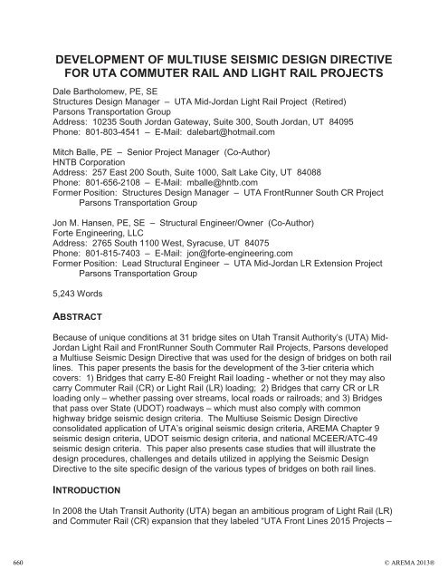
Development of Multiuse Seismic Design Directive for UTA ... - AREMA
Development of Multiuse Seismic Design Directive for UTA ... - AREMA
Development of Multiuse Seismic Design Directive for UTA ... - AREMA

Create successful ePaper yourself
Turn your PDF publications into a flip-book with our unique Google optimized e-Paper software.
DEVELOPMENT OF MULTIUSE SEISMIC DESIGN DIRECTIVE<br />
FOR <strong>UTA</strong> COMMUTER RAIL AND LIGHT RAIL PROJECTS<br />
Dale Bartholomew, PE, SE<br />
Structures <strong>Design</strong> Manager – <strong>UTA</strong> Mid-Jordan Light Rail Project (Retired)<br />
Parsons Transportation Group<br />
Address: 10235 South Jordan Gateway, Suite 300, South Jordan, UT 84095<br />
Phone: 801-803-4541 – E-Mail: dalebart@hotmail.com<br />
Mitch Balle, PE – Senior Project Manager (Co-Author)<br />
HNTB Corporation<br />
Address: 257 East 200 South, Suite 1000, Salt Lake City, UT 84088<br />
Phone: 801-656-2108 – E-Mail: mballe@hntb.com<br />
Former Position: Structures <strong>Design</strong> Manager – <strong>UTA</strong> FrontRunner South CR Project<br />
Parsons Transportation Group<br />
Jon M. Hansen, PE, SE – Structural Engineer/Owner (Co-Author)<br />
Forte Engineering, LLC<br />
Address: 2765 South 1100 West, Syracuse, UT 84075<br />
Phone: 801-815-7403 – E-Mail: jon@<strong>for</strong>te-engineering.com<br />
Former Position: Lead Structural Engineer – <strong>UTA</strong> Mid-Jordan LR Extension Project<br />
Parsons Transportation Group<br />
5,243 Words<br />
ABSTRACT<br />
Because <strong>of</strong> unique conditions at 31 bridge sites on Utah Transit Authority’s (<strong>UTA</strong>) Mid-<br />
Jordan Light Rail and FrontRunner South Commuter Rail Projects, Parsons developed<br />
a <strong>Multiuse</strong> <strong>Seismic</strong> <strong>Design</strong> <strong>Directive</strong> that was used <strong>for</strong> the design <strong>of</strong> bridges on both rail<br />
lines. This paper presents the basis <strong>for</strong> the development <strong>of</strong> the 3-tier criteria which<br />
covers: 1) Bridges that carry E-80 Freight Rail loading - whether or not they may also<br />
carry Commuter Rail (CR) or Light Rail (LR) loading; 2) Bridges that carry CR or LR<br />
loading only – whether passing over streams, local roads or railroads; and 3) Bridges<br />
that pass over State (UDOT) roadways – which must also comply with common<br />
highway bridge seismic design criteria. The <strong>Multiuse</strong> <strong>Seismic</strong> <strong>Design</strong> <strong>Directive</strong><br />
consolidated application <strong>of</strong> <strong>UTA</strong>’s original seismic design criteria, <strong>AREMA</strong> Chapter 9<br />
seismic design criteria, UDOT seismic design criteria, and national MCEER/ATC-49<br />
seismic design criteria. This paper also presents case studies that will illustrate the<br />
design procedures, challenges and details utilized in applying the <strong>Seismic</strong> <strong>Design</strong><br />
<strong>Directive</strong> to the site specific design <strong>of</strong> the various types <strong>of</strong> bridges on both rail lines.<br />
INTRODUCTION<br />
In 2008 the Utah Transit Authority (<strong>UTA</strong>) began an ambitious program <strong>of</strong> Light Rail (LR)<br />
and Commuter Rail (CR) expansion that they labeled “<strong>UTA</strong> Front Lines 2015 Projects –<br />
660<br />
© <strong>AREMA</strong> 2013®
Building 70 miles <strong>of</strong> rail in 7 years” (Figure 1). This program more than doubled the<br />
mileage <strong>of</strong> their current rail systems and involved 6 separate, but related projects,<br />
including four LR extensions, one CR extension, and one new Service Center or LR<br />
vehicle maintenance facility.<br />
Building 70 miles <strong>of</strong> rail in 7 years<br />
Figure 1 – <strong>UTA</strong> FrontLines 2015 Projects<br />
© <strong>AREMA</strong> 2013® 661
Parsons provided design services <strong>for</strong> the two longest rail segments, the 44 mile<br />
FrontRunner South Commuter Rail Line (FRSCR) extension from Provo to Salt Lake<br />
City, UT and the 10.6 mile Mid-Jordan Light Rail Line (MJLR) double track extension to<br />
Daybreak, UT. The MJLR Project has 7 track support bridges and the FRSCR Project<br />
has 24 that each required seismic design to various criteria.<br />
Because the MJLR Line utilizes a <strong>for</strong>mer freight rail right-<strong>of</strong>-way and must continue to<br />
accommodate freight rail traffic, 4 <strong>of</strong> the 7 bridges support both freight rail and light rail<br />
traffic (Figure 2) while the remaining 3 bridges support light rail traffic only. One LR only<br />
bridge (Figure 3) and one dual traffic bridge pass over Utah Department <strong>of</strong><br />
Transportation (UDOT) roadways.<br />
Figure 2 – <strong>UTA</strong> Mid-Jordan LR Line<br />
Jordan River Bridge<br />
Figure 3 - <strong>UTA</strong> Mid-Jordan LR Line<br />
7200 South Bridge<br />
The separate FRSCR Line closely parallels the Provo to Salt Lake City, UT portion <strong>of</strong><br />
Union Pacific Railroad’s (UPRR) main line between Denver, CO and Salt Lake City, UT<br />
and utilizes a portion <strong>of</strong> UPRR right-<strong>of</strong>-way that <strong>UTA</strong> purchased from the UPRR in 2002.<br />
Because <strong>of</strong> tight geometric constraints under some overhead crossings and through the<br />
Jordan River Narrows canyon area, the UPRR main line had to be relocated at several<br />
locations. Because <strong>of</strong> these relocations and because <strong>of</strong> the need to maintain UPRR<br />
access to several industries on the opposite side <strong>of</strong> the FRSCR Line, 1 bridge on the<br />
FRSCR Project supports both freight rail and commuter rail traffic, 4 bridges support<br />
freight rail traffic only, and the remaining 19 bridges support commuter rail traffic only<br />
(Figure 4). Of these 24 FRSCR Line bridges, 12 pass over State highways (Figure 5).<br />
662<br />
© <strong>AREMA</strong> 2013®
Figure 4 – <strong>UTA</strong> FrontRunner South<br />
CR Line – UPRR Flyover Bridge<br />
Figure 5 - <strong>UTA</strong> FrontRunner South<br />
CR Line – 10600 South Bridge<br />
Following <strong>UTA</strong> contract requirements, Parsons located the lead design team <strong>for</strong> both<br />
projects in <strong>UTA</strong>’s headquarters in Salt Lake City, UT. Due to the relatively large number<br />
<strong>of</strong> bridges on the two lines and the short time frame <strong>for</strong> design completion, Parsons also<br />
assigned design responsibility <strong>for</strong> many specific bridges to staff in several other Parsons<br />
and subconsultant design <strong>of</strong>fices located throughout the US.<br />
While all designers were experienced bridge engineers and worked under the direction<br />
<strong>of</strong> a Structures <strong>Design</strong> Manager, there were varying levels <strong>of</strong> experience with rail<br />
bridges and seismic design procedures. Even so, there still was a number <strong>of</strong> strong<br />
divergent opinions as to which seismic design criteria should be followed and on how<br />
they should be applied.<br />
To complicate things, <strong>UTA</strong>’s original bridge design criteria (1) stipulated that seismic<br />
design <strong>of</strong> all structures should follow the American Railway Engineering and<br />
Maintenance-<strong>of</strong>-Way Association (<strong>AREMA</strong>) Chapter 9 seismic design criteria (2) and<br />
UDOT seismic design criteria (3), applicable to highway bridges. Ongoing discussions<br />
with <strong>UTA</strong> and UDOT confirmed that all structures that carry <strong>UTA</strong> rail traffic only and/or<br />
all structures that cross over UDOT right-<strong>of</strong>-way must comply with the UDOT seismic<br />
design criteria which referenced MCEER/ATC-49 (4) at the time.<br />
It soon became clear to the Structures <strong>Design</strong> Managers from both projects, that to<br />
eliminate confusion over the application <strong>of</strong> the various seismic design criteria and to<br />
unify as many <strong>of</strong> the strong opinions as possible, a consensus building seismic design<br />
workshop would have to be conducted. Thus, one or two lead bridge design engineers<br />
from each <strong>of</strong>fice were brought into the <strong>UTA</strong> Salt Lake City, UT <strong>Design</strong> Office <strong>for</strong> an allday<br />
seismic design workshop.<br />
This paper presents the basis <strong>for</strong> the development <strong>of</strong> the <strong>Multiuse</strong> <strong>Seismic</strong> <strong>Design</strong><br />
<strong>Directive</strong> (MSDD) that resulted from the workshop and was used <strong>for</strong> both the MJLR and<br />
FRSCR Projects. This MSDD covers: 1) Bridges that carry E-80 Freight Rail loading,<br />
© <strong>AREMA</strong> 2013® 663
whether or not they may also carry CR or LR loading; 2) Bridges that carry CR or LR<br />
loading only, whether passing over streams, local roads or railroads; and 3) Bridges<br />
that pass over State (UDOT) roadways, which must also comply with common highway<br />
bridge seismic design criteria. Thus the MSDD consolidated application <strong>of</strong> <strong>UTA</strong>’s<br />
original seismic design criteria, <strong>AREMA</strong> Chapter 9 seismic design criteria, UDOT<br />
seismic design criteria, and national MCEER/ATC-49 seismic design criteria.<br />
THE <strong>UTA</strong> SEISMIC DESIGN DIRECTIVE<br />
The <strong>UTA</strong> <strong>Multiuse</strong> <strong>Seismic</strong> <strong>Design</strong> <strong>Directive</strong> (MSDD), presented in Figure 6, was<br />
reviewed and approved by <strong>UTA</strong> and UDOT, led to compatibility revisions to the <strong>UTA</strong><br />
design criteria (1), and was used to modify the UDOT seismic design criteria <strong>for</strong> the<br />
design <strong>of</strong> track support bridges on the <strong>UTA</strong> Mid-Jordan Light Rail and FrontRunner<br />
South Commuter Rail Projects. This directive also clarifies what design specification is<br />
applicable to each particular bridge and helped to resolve conflicts between guidelines.<br />
THE MULTIUSE SEISMIC DESIGN DIRECTIVE BASIS OF DEVELOPMENT<br />
General<br />
The <strong>UTA</strong> MSDD was developed in 2008 and thus, was based on the 2007 <strong>AREMA</strong><br />
Manual <strong>of</strong> Railway Engineering, Chapter 9 (2) and other design criteria current at the<br />
time. Even though little change is apparent to articles referenced by the MSDD in the<br />
2013 edition <strong>of</strong> the <strong>AREMA</strong> Manual, some modification would likely be required to adapt<br />
it to current standards. The approach described herein, however, is reasonable <strong>for</strong><br />
such an update and is also appropriate <strong>for</strong> an adaptation to accommodate the current<br />
requirements <strong>of</strong> UDOT, now AASHTO based (5), or any other specific State DOT’s<br />
seismic design criteria.<br />
This section provides a description <strong>of</strong> the rationale or basis <strong>for</strong> each Article in the <strong>UTA</strong><br />
MSDD presented in Figure 6.<br />
664<br />
© <strong>AREMA</strong> 2013®
<strong>UTA</strong>H TRANSIT AUTHORITY<br />
COMMUTER RAIL / LIGHT RAIL<br />
DESIGN DIRECTIVE<br />
DATE: July 31, 2008 FILE CODE: [4-03]<br />
SUBJECT:<br />
<strong>Seismic</strong> <strong>Design</strong><br />
TITLE: <strong>Seismic</strong> <strong>Design</strong> <strong>Directive</strong> 2<br />
FROM:<br />
Mitch Balle, SE – Structures <strong>Design</strong> Manager<br />
1.0 INTRODUCTION<br />
1.1 Multiple Use Criteria (Freight Rail, Commuter Rail, and Light Rail)<br />
1.1.1 All Structures: <strong>AREMA</strong> Manual Chapter 9 seismic level 1<br />
requirements must be satisfied <strong>for</strong> all structures. <strong>AREMA</strong> Manual<br />
Chapter 9 seismic level 3 detailing requirements shall also be<br />
satisfied <strong>for</strong> all structures.<br />
1.1.2 Structures Impacting State Routes: UDOT “Life Safety”<br />
per<strong>for</strong>mance level requirements, per UDOT seismic design criteria<br />
and MCEER/ATC-49, shall be satisfied <strong>for</strong> underpasses crossing<br />
over state routes and walls within fifty feet <strong>of</strong> UDOT right-<strong>of</strong>-way.<br />
1.1.3 Commuter Rail or Light Rail Only Structures: Structures carrying<br />
commuter rail or light rail only shall also be analyzed to ensure<br />
UDOT “Life Safety” per<strong>for</strong>mance level requirements are met.<br />
1.2 Definition <strong>of</strong> Ordinary (Regular) Bridges – See MCEER/ATC-49<br />
Table 5.4.2.1-1<br />
Figure 6 – <strong>UTA</strong> Commuter Rail/Light Rail <strong>Seismic</strong> <strong>Design</strong> <strong>Directive</strong><br />
© <strong>AREMA</strong> 2013® 665
<strong>UTA</strong>H TRANSIT AUTHORITY<br />
COMMUTER RAIL / LIGHT RAIL<br />
DESIGN DIRECTIVE<br />
2.0 DEMANDS ON STRUCTURE COMPONENTS<br />
2.1 <strong>AREMA</strong> Chapter 9 Requirements <strong>for</strong> all Multiple Use Structures<br />
2.1.1 Ground Motion Representation<br />
2.1.1.1 Spectral Acceleration – Use site specific 40% probability<br />
in 50 year curves.<br />
2.1.1.2 Vertical Ground Motion – Ignore <strong>for</strong> level 1 ground<br />
motions.<br />
2.1.1.3 Load Combinations – per <strong>AREMA</strong> Manual 9-1.4.5.3.c,<br />
9-1.4.5.4.c, & 9-1.4.6.<br />
2.1.1.4 Damping – Use 10% Damping per <strong>AREMA</strong><br />
Manual 9-1.4.4.2.<br />
2.1.2 Force Demand<br />
2.1.2.1 Level 1 <strong>Design</strong> – All elements shall be designed to<br />
remain elastic <strong>for</strong> all <strong>for</strong>ces generated by level 1 ground<br />
motions. Response modification factors shall not be<br />
applied to <strong>for</strong>ces generated by level 1 ground motions.<br />
2.1.2.2 Level 3 Detailing Requirements<br />
2.1.2.2.1 Moment Demand – Column design <strong>for</strong> level 3<br />
moment is not required by <strong>AREMA</strong>.<br />
2.1.2.2.2 Shear Demand on Concrete Columns –<br />
Determine by the lesser <strong>of</strong> the requirements<br />
<strong>of</strong> <strong>AREMA</strong> Manual 9-1.4.7.2.1.a.(7) & (8) or<br />
the level 3 shear.<br />
2.1.2.2.3 Demands <strong>of</strong> Capacity Protected Members –<br />
Per <strong>AREMA</strong> Manual 9-1.4.7.3.1.<br />
Figure 6 (Continued) – <strong>UTA</strong> Commuter Rail/Light Rail <strong>Seismic</strong> <strong>Design</strong> <strong>Directive</strong><br />
666<br />
© <strong>AREMA</strong> 2013®
<strong>UTA</strong>H TRANSIT AUTHORITY<br />
COMMUTER RAIL / LIGHT RAIL<br />
DESIGN DIRECTIVE<br />
2.2 UDOT Requirements <strong>for</strong> Structures Impacting State Routes<br />
2.2.1 Ground Motion Representation<br />
2.2.1.1 Spectral Acceleration – Use site specific 2% probability in<br />
50 year curves. This is the maximum considered<br />
earthquake (MCE). For determining seismic hazard<br />
levels: FvS1 is determined from the site specific<br />
response spectra curve at a 1 second period. FaSs is<br />
determined from the specific response spectra curve<br />
at a 0.2 second period.<br />
2.2.1.2 Vertical Ground Motion – Use site specific 2% probability<br />
in 50 year curves<br />
2.2.1.3 Load Combinations – Per UDOT Structures <strong>Design</strong><br />
Criteria Section 6.3. Include no live load.<br />
2.2.1.4 Damping – Use 10% Damping per <strong>AREMA</strong><br />
Manual 9-1.4.4.2.<br />
2.2.2 Displacement Demand – <strong>Seismic</strong> <strong>Design</strong> and Analysis Procedure<br />
(SDAP) E may be used to reduce column size.<br />
2.2.3 Force Demand<br />
2.2.3.1 Moment Demand – Per SDAP D<br />
2.2.3.2 Shear Demand – Per SDAP D<br />
2.2.3.3 Demands <strong>of</strong> Capacity Protected Members – Per SDAP D<br />
2.3 Commuter Rail or Light Rail Only Structures – Use procedures as<br />
outlined in 2.2.<br />
Figure 6 (Continued) – <strong>UTA</strong> Commuter Rail/Light Rail <strong>Seismic</strong> <strong>Design</strong> <strong>Directive</strong><br />
© <strong>AREMA</strong> 2013® 667
<strong>UTA</strong>H TRANSIT AUTHORITY<br />
COMMUTER RAIL / LIGHT RAIL<br />
DESIGN DIRECTIVE<br />
3.0 BOUNDARY CONDITIONS FOR ALL MULTIPLE USE STRUCTURES<br />
3.1 Abutments<br />
3.2 Piers<br />
3.1.1 Longitudinal stiffness – Use a passive pressure (Pp) <strong>of</strong> 2H/3 ksf per<br />
foot <strong>of</strong> abutment length but no greater than 7 ksf. Use 0.005H as<br />
the soil displacement required to mobilize the full passive pressure.<br />
Determine effective stiffness using Pp/(0.005H + Dg) and account<br />
<strong>for</strong> the bilinear behavior <strong>of</strong> the soil (see Figure 7.5.2.2-2 in<br />
MCEER). Include gaps due to permanent soil de<strong>for</strong>mation and<br />
compressibility <strong>of</strong> joint filler materials in Dg. Include the stiffness <strong>of</strong><br />
the abutment piles when appropriate.<br />
3.1.2 Transverse Stiffness – Similar to longitudinal stiffness. See<br />
MCEER Section 7.5.3 <strong>for</strong> detailed discussion. Also see Section<br />
7.8.2 <strong>of</strong> CALTRANS <strong>Seismic</strong> <strong>Design</strong> Criteria.<br />
3.2.1 Exposed Pile Bents and Drilled Shafts – The soil-structure<br />
interaction shall be accounted <strong>for</strong> in determining stiffness.<br />
3.2.2 Below Grade Pile Supported Foundations<br />
3.2.2.1 Include foundation stiffness per MCEER Section 8.4 <strong>for</strong><br />
structures impacting state routes and <strong>for</strong> commuter rail<br />
only or light rail only structures.<br />
3.2.2.2 Foundation stiffness may be included <strong>for</strong> freight rail<br />
structures not impacting state routes.<br />
Figure 6 (Continued) – <strong>UTA</strong> Commuter Rail/Light Rail <strong>Seismic</strong> <strong>Design</strong> <strong>Directive</strong><br />
668<br />
© <strong>AREMA</strong> 2013®
Multiple Use Criteria (Freight Rail, Commuter Rail, and Light Rail)<br />
Article 1.1.1 All Structures<br />
For all types <strong>of</strong> rail traffic to be carried, <strong>UTA</strong>’s design criteria (1) requires that all<br />
structures supporting track be designed to meet <strong>AREMA</strong> Manual requirements, as a<br />
minimum, including the seismic design requirements <strong>of</strong> Chapter 9 (2). When applicable,<br />
UDOT requirements (3) are in addition to <strong>AREMA</strong>’s.<br />
Article 1.1.2 Structures Impacting State Routes<br />
This article is based on the UDOT requirement that bridges going over state routes must<br />
also satisfy their seismic design criteria (3). UDOT agreed that only their “Life Safety”<br />
requirements needed to be satisfied. While UDOT has a two level criteria <strong>for</strong> their<br />
bridges that references the MCEER/ATC-49 (4) requirements, they allowed us to follow<br />
<strong>AREMA</strong> Manual Chapter 9 requirements (2) <strong>for</strong> the lower level seismic design (level 1).<br />
Article 1.1.3 Commuter Rail or Light Rail Only Structures<br />
Vertical and lateral loads <strong>for</strong> commuter rail and light rail traffic are much lower than<br />
those <strong>for</strong> freight rail traffic. Many on the bridge design team were concerned that if we<br />
followed the <strong>AREMA</strong> Manual’s approach <strong>for</strong> seismic design <strong>of</strong> these lighter loaded<br />
bridges, the lateral resistance might be insufficient. Thus, to make seismic resistance<br />
consistent <strong>for</strong> all track support bridges on the two <strong>UTA</strong> Projects, this Article requires that<br />
bridges supporting only commuter rail or light rail must also satisfy UDOT “life-safety”<br />
requirements.<br />
Ordinary Structures<br />
Article 1.2 Definition <strong>of</strong> Ordinary (Regular) Bridges<br />
Table 5.4.2.1-1 in MCEER/ATC-49 (4) defines what bridges can be analyzed using the<br />
simpler “uni<strong>for</strong>m load” method” or whether a more complex “multi-modal dynamic”<br />
analysis must be per<strong>for</strong>med. This table has three parameters:<br />
The angle subtended by a curved bridge.<br />
The span length ratio from span to span<br />
The bent/pier stiffness ratio from span to span.<br />
This definition was adopted so that the approach <strong>for</strong> analysis would satisfy UDOT’s<br />
seismic design criteria.<br />
Demand on Structure Components<br />
Part 2.1 <strong>AREMA</strong> Chapter 9 Requirements <strong>for</strong> all Multiple Use Structures<br />
Article 2.1.1 Ground Motion Representation As stated in Article 1.1.1, <strong>AREMA</strong><br />
requirements <strong>for</strong> level 1 analysis is used <strong>for</strong> all rail structures. The consensus at the<br />
© <strong>AREMA</strong> 2013® 669
seismic design workshop was that the longest return period from <strong>AREMA</strong>’s level one<br />
criteria should be used which is a level 1 ground motion with a 40% probability in 50<br />
years. The geotechnical engineers provided site specific response spectra <strong>for</strong> each<br />
bridge site covering this ground motion probability and recurrence interval (See example<br />
in Figure 13). Vertical ground motions <strong>for</strong> level 1 analysis are ignored since the vertical<br />
live load effects are greater even <strong>for</strong> LR loading. It was determined that 10% damping<br />
is appropriate in the longitudinal direction <strong>for</strong> all bridges with continuous rail across the<br />
bridge. See Commentary in <strong>AREMA</strong> Manual, Chapter 9.<br />
Article 2.1.2.1 Force Demand – Level 1 <strong>Design</strong> Since the MSDD covers railroad or<br />
track support bridges in all cases, <strong>AREMA</strong> requirements <strong>for</strong> level 1 ground motion are to<br />
be followed. All elements are to respond elastically to the <strong>for</strong>ces induced by the level 1<br />
ground motions.<br />
Article 2.1.2.2 Force Demand – Level 3 Detailing Requirements Also as stated in<br />
Article 1.1.1, <strong>AREMA</strong> detailing requirements <strong>for</strong> level 3 are to be followed <strong>for</strong> all track<br />
support bridges. During the seismic design workshop, we considered meeting the<br />
recently updated (prior to 2008) AASHTO guide specifications <strong>for</strong> seismic design and,<br />
even though it may be a relatively simple adjustment, the MSDD is applicable to<br />
railroad or track support bridges so <strong>AREMA</strong> Chapter 9 was used.<br />
Part 2.2 UDOT Requirements <strong>for</strong> Structures Impacting State Routes<br />
Article 2.2.1 Ground Motion Representation In this Part, the MSDD modifies and<br />
clarifies UDOT level 3 requirements that are not oriented toward railroad bridges. Some<br />
<strong>of</strong> <strong>AREMA</strong> Chapter 9’s criteria <strong>for</strong> level 3 analysis must be used.<br />
Article 2.2.1.1 Spectral Acceleration This Article describes how the seismic hazard<br />
level values can be derived from the site specific response spectra curves <strong>for</strong> a level 3<br />
ground motion with 2% probability in 50 year as required by UDOT. The geotechnical<br />
engineers provided site specific response spectra that covered this ground motion<br />
probability and recurrence interval <strong>for</strong> each bridge site impacting State Routes (See<br />
Figure 14).<br />
Article 2.2.1.2 Vertical Ground Motion In accordance with UDOT seismic design<br />
criteria, this article requires the application <strong>of</strong> site specific vertical ground motions <strong>for</strong><br />
level 3 design only.<br />
Article 2.2.1.3 Load Combinations UDOT requires the inclusion <strong>of</strong> live load with<br />
seismic load in their load combinations. However, since the MSDD is applicable to track<br />
support structures where the probability <strong>of</strong> a train being on the bridge during a seismic<br />
event is low, <strong>AREMA</strong> Chapter 9 is followed so that the inclusion <strong>of</strong> live load with seismic<br />
load is not required.<br />
Article 2.2.1.4 Damping UDOT requires the use <strong>of</strong> 5% damping, but that is not<br />
oriented toward railroad bridges supporting continuous rails. Thus again, 10% damping<br />
670<br />
© <strong>AREMA</strong> 2013®
is appropriate in the longitudinal direction <strong>for</strong> all rail bridges.<br />
Article 2.2.2 Displacement Demand <strong>Seismic</strong> <strong>Design</strong> and Analysis Procedure E<br />
(SDAP E) is a displacement analysis approach defined in the MCEER/ATC-49 seismic<br />
design criteria that is accepted by UDOT. This provision allows the use <strong>of</strong> a<br />
displacement approach <strong>for</strong> level 3 seismic design that may result in a smaller column<br />
size. The current AASHTO guidelines (5) have simplified procedures <strong>for</strong> using a<br />
displacement analysis approach that may reduce the design ef<strong>for</strong>t further.<br />
Article 2.2.3 Force Demand <strong>Seismic</strong> <strong>Design</strong> and Analysis Procedure D (SDAP D),<br />
Elastic Response Spectrum Method, is a one step design procedure using an elastic<br />
(cracked section properties) analysis that is also defined in the MCEER/ATC-49 seismic<br />
design criteria and is accepted by UDOT. This approach is stipulated in the MSDD to<br />
promote design approach uni<strong>for</strong>mity and reduce design time.<br />
Part 2.3 Commuter Rail or Light Rail Only Structures<br />
To accommodate <strong>UTA</strong>’s refined design criteria, this Article requires that commuter rail or<br />
light rail only bridges follow the same procedures as required <strong>for</strong> bridges impacting State<br />
routes. This also creates a loop hole <strong>for</strong> bridges carrying freight traffic that do not<br />
impact State routes. These need only satisfy <strong>AREMA</strong> Chapter 9 seismic requirements.<br />
Boundary Conditions <strong>for</strong> All Multiple Use Structures<br />
Part 3.1 Abutments<br />
Article 3.1.1 Longitudinal Stiffness Section 3.0 <strong>of</strong> the MSDD defines what to use <strong>for</strong><br />
boundary conditions. The effects <strong>of</strong> the rails are not included in the boundary conditions<br />
due to lack <strong>of</strong> guidance in any <strong>of</strong> the seismic design criterias. Only the effects <strong>of</strong> soil<br />
around the abutments and piles are included.<br />
MCEER gives some appropriate guidance on how to account <strong>for</strong> the soil stiffness.<br />
Being railroad track support structures, however, the abutment backwalls invariably are<br />
very stout due to the high surcharge loads from daily train traffic which also causes<br />
continual compaction <strong>of</strong> the soil behind abutments. This will prevent the backwalls from<br />
breaking away during a level 3 earthquake to reduce the seismic loads transferred into<br />
the abutments. The passive resistance <strong>of</strong> the soil behind the full height <strong>of</strong> the abutment,<br />
however, is mobilized allowing most <strong>of</strong> the longitudinal seismic load to transfer directly<br />
into the soil. Because <strong>of</strong> the continual compaction, the geotechnical engineers<br />
recommended the use <strong>of</strong> the 0.005 factor, instead <strong>of</strong> MCEER’s 0.02, in the <strong>for</strong>mula <strong>for</strong><br />
calculating the soil displacement required to mobilize the full passive resistance.<br />
The MSDD also includes the stiffness <strong>of</strong> piles because the passive resistance behind<br />
the abutments will not always resist the entire longitudinal seismic load..<br />
© <strong>AREMA</strong> 2013® 671
Article 3.1.2 Transverse Stiffness In Article 3.1.2, the MSDD is directing the<br />
designer to guidance. CALTRANS <strong>Seismic</strong> <strong>Design</strong> Criteria (6) is helpful. The boundary<br />
conditions have a large effect on the design. More detailed guidance from <strong>AREMA</strong> on<br />
how to account <strong>for</strong> the rail would be helpful. Thus, the effects <strong>of</strong> the rails are ignored.<br />
Part 3.2 Piers<br />
Article 3.2.1 Exposed Pile Bents and Drilled Shafts This Article delineates the<br />
appropriate approach <strong>for</strong> pier or bent design and multi-modal analysis.<br />
Article 3.2.2 Below Grade Pile Supported Foundations In this Article, the MSDD is<br />
directing the designer where to look <strong>for</strong> guidance and indicating that it is acceptable to<br />
also use this criteria <strong>for</strong> the design <strong>of</strong> freight rail track support structures.<br />
APPLICATION OF THE <strong>UTA</strong> MULTIUSE SEISMIC DESIGN DIRECTIVE<br />
Mid-Jordan Light Rail Line Case Studies<br />
To illustrate the design procedures, challenges and details utilized in applying the<br />
MSDD to the site specific design <strong>of</strong> the various types <strong>of</strong> bridges on both rail lines,<br />
specific bridge case studies from the MJLR Line are presented herein. Essentially<br />
identical procedures and details were utilized on the FRSCR Line.<br />
Three Types <strong>of</strong> <strong>Seismic</strong> <strong>Design</strong><br />
As addressed in the MSDD, there are three types <strong>of</strong> track support bridge seismic design<br />
that needed to be per<strong>for</strong>med on the MJLR Line:<br />
Type 1: Freight E-80/LRT Loading, <strong>AREMA</strong> Chapter 9 <strong>Seismic</strong> <strong>Design</strong> Only<br />
Type 2: LRT Loading Only, <strong>AREMA</strong> Chapter 9 plus MCEER/ATC-49 (Light<br />
Rail) <strong>Seismic</strong> <strong>Design</strong><br />
Type 3: Over State Road, <strong>AREMA</strong> Chapter 9 plus MCEER/ATC-49 (Light Rail<br />
and/or Freight E-80) <strong>Seismic</strong> <strong>Design</strong><br />
Bridge Configurations and Girder & Bent Types<br />
Type 1 –3 Bridges<br />
o Jordan River Bridge – Straight bridge with curved track – See Figures 7 & 8<br />
• 3 spans <strong>of</strong> 2 double cell concrete box girders per span.<br />
• 2 exposed pile bents with normal pile orientation including battered<br />
piles and cross bracing.<br />
o Utah & Salt Lake Canal Bridge<br />
• 1 Span <strong>of</strong> 2 double cell concrete box girders per span.<br />
• No bents.<br />
o Winchester Street Bridge<br />
672<br />
© <strong>AREMA</strong> 2013®
• 3 Spans <strong>of</strong> 4 staggered single cell concrete box girders per span.<br />
• 2 exposed pile bents with 18 degree skew, normal pile orientation,<br />
non-battered piles, and cross bracing.<br />
Figure 7 – Jordan River Bridge<br />
Elevation<br />
Figure 8 – Jordan River Bridge<br />
Girders & Bents<br />
Type 2 – 2 Bridges<br />
o<br />
o<br />
700 West Bridge<br />
• 4 Spans <strong>of</strong> 2 double cell concrete box girders per span.<br />
• 3 exposed pile bents with rotated pile orientation, non-battered piles,<br />
and no cross bracing.<br />
7800 South Bridge – Straight spans corded along curved track<br />
• 5 Spans <strong>of</strong> steel wide flange rolled beams with cast-in-place composite<br />
concrete ballast deck.<br />
• 4 cast-in-place concrete bents with 2 columns, up to 50 degrees <strong>of</strong><br />
skew, and drilled shaft foundations.<br />
Type 3 – 2 Bridges<br />
o 7200 South Bridge – See Figures 9, 10, 17 & 19<br />
• 4 Spans <strong>of</strong> 2 double cell concrete box girders per span.<br />
• 3 exposed pile bents with rotated pile orientation, non-battered piles,<br />
and no cross bracing.<br />
o Bangerter Highway Bridge – See Figures 11, 12, & 18<br />
• 2 Spans <strong>of</strong> 4 staggered single cell concrete box girders per span.<br />
• 1 cast-in-place concrete bent with 1 column, 21 degree skew, and<br />
drilled shaft foundation.<br />
© <strong>AREMA</strong> 2013® 673
Figure 9 – 7200 South Bridge<br />
Elevation<br />
Figure 10 – 7200 South Bridge<br />
Girders & Bents<br />
Figure 11 – Bangerter Highway Bridge<br />
One Quarter Side View<br />
Figure 12 – Bangerter Highway Bridge<br />
Girder & Bent<br />
<strong>Seismic</strong> <strong>Design</strong> Challenges<br />
Different types <strong>of</strong> design challenges were encountered with each bridge configuration<br />
and with each type <strong>of</strong> seismic design that needed to be per<strong>for</strong>med. The greatest<br />
challenges were with the Type 2 and Type 3 seismic designs. The primary challenges<br />
encountered included the following:<br />
Type 1 Challenges<br />
o Many designers needed to become familiar with <strong>AREMA</strong> Chapter 9<br />
674<br />
© <strong>AREMA</strong> 2013®
o<br />
Limited detailing guidance <strong>for</strong> exposed pile bents<br />
Type 2 & 3 Challenges<br />
o<br />
o<br />
o<br />
o<br />
o<br />
o<br />
o<br />
o<br />
o<br />
o<br />
Many designers needed to become familiar with MCEER/ATC-94.<br />
Ensuring all design <strong>of</strong>fices working on the project understood and<br />
appropriately applied the <strong>UTA</strong> MSDD.<br />
Meshing MCEER/ATC-94 with <strong>AREMA</strong> Chapter 9 and <strong>UTA</strong> Light Rail<br />
<strong>Design</strong> Criteria.<br />
Ensuring <strong>AREMA</strong> Chapter 9 criteria was met at a minimum.<br />
Minimizing seismic design cost increase from base-line design – typically a<br />
25% to 33% increase in number <strong>of</strong> piles was required.<br />
The need to increase pile or substructure capacity in the transverse<br />
direction – frequently accommodated by rotating the abutment and/or bent<br />
pile orientation by 90 degrees.<br />
The need to increase girder translation restraint capacity in the transverse<br />
direction – frequently accommodated by replacing the UPRR/BNSF<br />
Standard side restrainer brackets with stronger concrete shear blocks.<br />
The need to increase exposed pile bent capacity in the longitudinal and<br />
transverse directions and to ensure that piles remain elastic below grade<br />
during a major seismic event where inspections can not easily be per<strong>for</strong>med<br />
– frequently accommodated by utilizing or increasing the depth <strong>of</strong><br />
cast-in-place concrete bent collars to increase the passive resistance<br />
provided by the adjacent soil.<br />
Including and accommodating vertical acceleration into the seismic design.<br />
Many designers needed to become familiar with multi-modal analysis and<br />
s<strong>of</strong>tware utilization.<br />
Geotechnical Input and <strong>Seismic</strong> <strong>Design</strong> Procedures Utilized<br />
<strong>Seismic</strong> <strong>Design</strong> Response Spectra<br />
In con<strong>for</strong>mance with the MSDD, the geotechnical engineers provided site-specific<br />
seismic response spectra curves <strong>for</strong> level 1 ground motion with a 40% probability in 50<br />
years and <strong>for</strong> level 3 ground motion with a 2% probability in 50 years <strong>for</strong> each bridge<br />
site. These response spectra were adjusted <strong>for</strong> site coefficient, S, and <strong>for</strong> fault<br />
proximity. Vertical acceleration curves were included that were corrected <strong>for</strong> a minimum<br />
<strong>of</strong> 80% <strong>of</strong> horizontal. See Figures 13 and 14 <strong>for</strong> example site-specific seismic response<br />
spectra curves that were provided <strong>for</strong> the 7200 South Bridge.<br />
Abutment Passive Pressure and Stiffness<br />
In con<strong>for</strong>mance with Article 2.2.2, Article 2.2.3, and Article 3.1.1 <strong>of</strong> the MSDD,<br />
MCEER/ATC-49 <strong>Seismic</strong> <strong>Design</strong> and Analysis Procedures D & E and the effective<br />
passive stiffness <strong>for</strong>mula, Pp/(0.005H+Dg), were used <strong>for</strong> level 3 seismic design <strong>of</strong> the<br />
Type 2 & 3 bridge abutments. This is also per the geotechnical engineer which<br />
© <strong>AREMA</strong> 2013® 675
ecommended that 0.005H deflection be used instead <strong>of</strong> 0.02H, These procedures are<br />
described in MCEER/ATC-49 Article 7.5.2.2 with MCEER/ATC-49 Figure 7.5.2.2-2<br />
providing the “Characterization <strong>of</strong> Abutment Capacity and Stiffness” <strong>for</strong> “Seat<br />
Abutments” <strong>of</strong> the type used <strong>for</strong> rail bridges (See Figure 15).<br />
Figure 13 – MJLR Line 7200 South Bridge <strong>Design</strong> Response Spectra<br />
40% Probability in 50 Years<br />
676<br />
© <strong>AREMA</strong> 2013®
Figure 14 – MJLR Line 7200 South Bridge <strong>Design</strong> Response Spectra<br />
2% Probability in 50 Years<br />
Figure 15 – MCEER Figure 7.5.2.2-2 – Abutment Capacity and Stiffness<br />
© <strong>AREMA</strong> 2013® 677
Most <strong>of</strong> the bridges on <strong>UTA</strong>’s MJLR and FRSCR Lines are concrete box girder bridges<br />
patterned after the BNSF/UP Standard concrete trestle plans (7). As such, most<br />
bridges use joint filler packed tight between spans and abutments as shown in<br />
Figure 16. While this joint filler is slightly compressible and can not be initially installed<br />
perfectly tight in all joints, the high surcharge loads induced on the abutment backwalls<br />
by the everyday train traffic causes a continual tightening <strong>of</strong> the joint fillers. Because <strong>of</strong><br />
this, the gap width, Dg, was assumed to be no greater than 1/8 inch to 1/4 inch. This<br />
allows the box girder spans to act as a strut between abutments and to transfer most <strong>of</strong><br />
the longitudinal loads to the abutment backwall <strong>for</strong> passive resistance. This accounted<br />
<strong>for</strong> 60% - 80% <strong>of</strong> bridge longitudinal resistance.<br />
Figure 16 – <strong>UTA</strong> Concrete Box Girder Span Abutment Back Wall Configuration<br />
<strong>Seismic</strong> <strong>Design</strong> Details Utilized<br />
Type 1 Bridges<br />
All Type 1 concrete box girder span bridges essentially followed the BNSF/UP Standard<br />
concrete trestle plans (7) <strong>for</strong> all span, abutment, and bent elements and required no<br />
special details to accommodate seismic design criteria. See photos <strong>of</strong> the Jordan River<br />
Bridge in Figures 7 & 8 above.<br />
Type 2 & 3 Bridges<br />
678<br />
© <strong>AREMA</strong> 2013®
Rotating Abutment and/or Bent Pile Orientation 90 Degrees In order to increase<br />
pile or substructure capacity in the transverse direction to accommodate seismic design<br />
requirements, abutment or bent piles were rotated 90 degrees from the typical or<br />
standard orientation. See the partial Pile Plan <strong>for</strong> the 7200 South Bridge in Figure 17<br />
and the bent photo in Figure 10 above.<br />
Figure 17 – 7200 South Bridge – Partial Pile Plan<br />
Concrete Shear Block Girder Restrainers In order to increase girder translation<br />
restraint capacity in the transverse direction to accommodate seismic design<br />
requirements and to provide stability to deep single cell box girders, heavy concrete<br />
shear blocks were added beside the girders on bent cap ends. See the bridge Section<br />
View <strong>for</strong> the Bangerter Highway Bridge in Figure 18, the bridge Section View <strong>for</strong> the<br />
7200 South Bridge in Figure 19, and the girder and bent photos in Figures 10 & 12.<br />
© <strong>AREMA</strong> 2013® 679
Figure 18 – Bangerter Highway Bridge – Section View<br />
Cast-in-Place Concrete Bent Collars In order to increase exposed pile bent capacity<br />
in the longitudinal and transverse directions and to ensure that piles remain elastic<br />
below grade during a major seismic event, cast-in-place concrete bent collars were<br />
added or had their depth increased to provide additional passive resistance against the<br />
adjacent soil. The collars also will <strong>for</strong>ce the plastic hinge failure point <strong>of</strong> the pile to occur<br />
above grade and above the top <strong>of</strong> the collar where inspections can be per<strong>for</strong>med<br />
following a major seismic event. See the bridge Section View <strong>for</strong> the 7200 South Bridge<br />
in Figure 19 and the girder and bent photo in Figure 10 above.<br />
680<br />
© <strong>AREMA</strong> 2013®
Figure 19 – 7200 South Bridge – Section View<br />
© <strong>AREMA</strong> 2013® 681
CONCLUSION<br />
When undertaking a large rail project involving the design <strong>of</strong> many track support bridges<br />
in a high seismicity zone, conducting a seismic design workshop to build consensus<br />
among the members <strong>of</strong> a large design team will save considerable design time and<br />
provide uni<strong>for</strong>mity <strong>of</strong> seismic design process and details incorporated into the project.<br />
This should be conducted very early after project startup and lead to development <strong>of</strong> a<br />
<strong>Seismic</strong> <strong>Design</strong> <strong>Directive</strong> that will consolidate application <strong>of</strong> the rail client’s or agency’s<br />
seismic design criteria, <strong>AREMA</strong> Chapter 9 seismic design criteria, State DOT seismic<br />
design criteria, AASHTO’s seismic design criteria and national MCEER/ATC-49 seismic<br />
design criteria, as applicable.<br />
ACKNOWLEDGEMENTS<br />
The authors are grateful <strong>for</strong> the support and encouragement <strong>of</strong> the Utah Transit<br />
Authority, the client and bridge owner, as well as the repeated urging <strong>of</strong> <strong>AREMA</strong><br />
Committee 9 leadership, the committee <strong>for</strong> the <strong>Seismic</strong> <strong>Design</strong> <strong>of</strong> Railway Structures.<br />
Acknowledgement and appreciation must also be given <strong>for</strong> the support and input<br />
provided by the MJLR Line DB Contractor, Kiewit, Herzog, Parsons. a Joint Venture<br />
(KHP); the FRSCR Line CMGC Contractor, Commuter Rail Constructors (CRC, a joint<br />
venture <strong>of</strong> Stacy and Witbeck and Herzog); CRC’s bridge subcontractor, Ralph L.<br />
Wadsworth; the geotechnical engineer, Terracon Consultants, Inc.; and the Parsons<br />
bridge design team and company management. Dale Bartholomew also wishes to<br />
thank his co-authors, Mitch Balle and Jon Hansen <strong>for</strong> their assistance and input into the<br />
preparation <strong>of</strong> this paper and presentation adapted from their original presentations to<br />
<strong>AREMA</strong> Committee 9 at the June 23, 2009 meeting in Salt Lake City, UT.<br />
REFERENCES<br />
1. <strong>UTA</strong> (2007), Utah Transit Authority Light Rail <strong>Design</strong> Criteria, Chapter 7 -<br />
Structural, Revision 4, Nov. 2007, Utah Transit Authority, Salt Lake City, UT.<br />
2. <strong>AREMA</strong> (2007 & 2013), Manual <strong>for</strong> Railway Engineering, Vol. 2, Chapter 9 -<br />
<strong>Seismic</strong> <strong>Design</strong> <strong>for</strong> Railway Structures, American Railway Engineering and<br />
Maintenance-<strong>of</strong>-Way Association, Lanham, MD.<br />
3. UDOT (2008), UDOT Structures <strong>Design</strong> and Detailing Manual, Utah Department<br />
<strong>of</strong> Transportation, Salt Lake City, UT.<br />
4. MCEER/ATC-49 (2003), Recommended LRFD Guidelines <strong>for</strong> the <strong>Seismic</strong><br />
<strong>Design</strong> <strong>of</strong> Highway Bridges, Part I: Specifications and Part II: Commentary and<br />
Appendices, MCEER Report Number: MCEER-03-SP03, ATC/MCEER Joint<br />
Venture, a partnership <strong>of</strong> Applied Technology Council, Redwood City, CA, and<br />
Multidisciplinary Center <strong>for</strong> Earthquake Engineering Research, Buffalo, NY.<br />
5. AASHTO (2009), AASHTO Guide Specifications <strong>for</strong> LRFD <strong>Seismic</strong> Bridge<br />
682<br />
© <strong>AREMA</strong> 2013®
<strong>Design</strong>, 1 st ed., American Association <strong>of</strong> State Highway and Transportation<br />
Officials, Washington, DC.<br />
6. Caltrans (2006), Caltrans <strong>Seismic</strong> <strong>Design</strong> Criteria, Version 1.4, Cali<strong>for</strong>nia<br />
Department <strong>of</strong> Transportation, Sacramento, CA.<br />
7. BNSF/UP (2006), BNSF/UP Bridge Standards – Concrete Girder Bridges, BNSF<br />
Railway, Kansas City, KS and Union Pacific Railroad, Omaha, NE<br />
LIST OF FIGURES<br />
Figure 1. <strong>UTA</strong> FrontLines 2015 Projects<br />
Figure 2. <strong>UTA</strong> Mid-Jordan LR Line – Jordan River Bridge<br />
Figure 3. <strong>UTA</strong> Mid-Jordan LR Line – 7200 South Bridge<br />
Figure 4. <strong>UTA</strong> FrontRunner South CR Line – UPRR Flyover Bridge<br />
Figure 5. <strong>UTA</strong> FrontRunner South CR Line – 10600 South Bridge<br />
Figure 6. <strong>UTA</strong> Commuter Rail/Light Rail <strong>Seismic</strong> <strong>Design</strong> <strong>Directive</strong><br />
Figure 7. Jordan River Bridge – Elevation<br />
Figure 8. Jordan River Bridge – Girders & Bents<br />
Figure 9. 7200 South Bridge – Elevation<br />
Figure 10. 7200 South Bridge – Girders & Bents<br />
Figure 11. Bangerter Highway Bridge – One Quarter Side View<br />
Figure 12. Bangerter Highway Bridge – Girder & Bent<br />
Figure 13. MJLR Line 7200 South Bridge <strong>Design</strong> Response Spectra – 40%<br />
Probability in 50 Years<br />
Figure 14. MJLR Line 7200 South Bridge <strong>Design</strong> Response Spectra – 2%<br />
Probability in 50 Years<br />
Figure 15. MCEER Figure 7.5.2.2-2 – Abutment Capacity and Stiffness<br />
Figure 16. <strong>UTA</strong> Concrete Box Girder Span Abutment Back Wall Configuration<br />
Figure 17. 7200 South Bridge – Partial Pile Plan<br />
Figure 18. Bangerter Highway Bridge – Section View<br />
Figure 19. 7200 South Bridge – Section View<br />
© <strong>AREMA</strong> 2013® 683
DEVELOPMENT OF MULTIUSE<br />
SEISMIC DESIGN DIRECTIVE<br />
FOR <strong>UTA</strong> COMMUTER RAIL AND<br />
LIGHT RAIL PROJECTS<br />
Author/Presenter: Dale Bartholomew, PE, SE<br />
Co-Author: Mitch Balle, PE<br />
Co-Author: Jon Hansen, PE, SE<br />
September 29 – October 2, 2013<br />
Indianapolis, IN<br />
684<br />
© <strong>AREMA</strong> 2013®
PRESENTATION OUTLINE<br />
INTRODUCTION<br />
INTRODUCTION<br />
THE <strong>UTA</strong> SEISMIC DESIGN DIRECTIVE<br />
Basis Of <strong>Development</strong><br />
Application<br />
CONCLUSION<br />
ACKNOWLEDGMENTS<br />
Building 70 miles <strong>of</strong> rail in 7 years<br />
Begun In 2008<br />
Four Light Rail Expansions<br />
One Commuter Rail Expansion<br />
One Light Rail Service Center<br />
September 29 – October 2, 2013<br />
Indianapolis, IN<br />
September 29 – October 2, 2013<br />
Indianapolis, IN<br />
INTRODUCTION<br />
PARSONS DESIGN<br />
SERVICES<br />
FrontRunner South<br />
Commuter Rail<br />
44 Miles<br />
Salt Lake City to<br />
Provo<br />
Mid-Jordan Light<br />
Rail Line<br />
10.6 Miles<br />
Double Track<br />
Provo<br />
Salt Lake City<br />
INTRODUCTION<br />
Mid-Jordan Light Rail Line<br />
Utilizes Former Freight Rail ROW<br />
Continues To Accommodate Freight Rail<br />
7 Track Support Bridges<br />
4 Bridges Support Freight & Light Rail<br />
Traffic<br />
3 Bridges Support Light Rail Traffic Only<br />
2 Bridges (1 Each Type) Pass Over UDOT<br />
Roadways<br />
September 29<br />
– October 2, 2013<br />
Indianapolis, n<br />
IN<br />
September 29 – October 2, 2013<br />
Indianapolis, IN<br />
INTRODUCTION<br />
Mid-Jordan Light Rail Line<br />
INTRODUCTION<br />
FrontRunner South Commuter Rail Line<br />
Jordan River Bridge<br />
Freight & Light Rail Traffic<br />
7200 South Bridge – UDOT<br />
Light Rail Traffic Only<br />
Parallels Union Pacific Railroad Main Line<br />
Separate <strong>UTA</strong> ROW Purchased From UPRR<br />
Some UPRR Main Line Relocations Required<br />
24 Track Support Bridges<br />
1 Bridge Supports Freight & Commuter Rail<br />
Traffic<br />
4 Bridges Support Freight Rail Traffic Only<br />
19 Bridges Support Commuter Rail Traffic Only<br />
12 Bridges Pass Over UDOT Roadways<br />
September 29 – October 2, 2013<br />
Indianapolis, IN<br />
September 29 – October 2, 2013<br />
Indianapolis, IN<br />
© <strong>AREMA</strong> 2013® 685
INTRODUCTION<br />
FrontRunner South Commuter Rail Line<br />
UPRR Flyover Bridge<br />
Commuter Rail Traffic Only<br />
September 29 – October 2, 2013<br />
Indianapolis, IN<br />
10600 South Bridge – UDOT<br />
Commuter Rail Traffic Only<br />
INTRODUCTION<br />
What <strong>Seismic</strong> <strong>Design</strong> Criteria Should Be<br />
Used For Both Projects?<br />
Lead Staff In <strong>UTA</strong>s SLC HQ Office<br />
Utilized Several <strong>Design</strong> Offices Nationwide<br />
Varying Levels <strong>of</strong> Experience With <strong>Seismic</strong><br />
<strong>Design</strong> and Railroad Bridges<br />
Still, Strong Divergent Opinions<br />
Which <strong>Seismic</strong> Criteria to Use<br />
How to Apply the Criteria<br />
September 29 – October 2, 2013<br />
Indianapolis, IN<br />
INTRODUCTION<br />
What <strong>Seismic</strong> <strong>Design</strong> Criteria Should Be<br />
Used For Both Projects?<br />
Original <strong>UTA</strong> <strong>Design</strong> Criteria Not Definitive<br />
on <strong>Seismic</strong> - Follow <strong>AREMA</strong> / UDOT / UBC<br />
UDOT <strong>Seismic</strong> Criteria Specific to Highway<br />
Bridges - Referenced MCEER/ATC-49<br />
INTRODUCTION<br />
<strong>Seismic</strong> <strong>Design</strong> Workshop<br />
Lead <strong>Design</strong>ers Brought In From All Offices<br />
All Day Workshop<br />
Unify Divergent Opinions<br />
Eliminate Confusion Over Application<br />
Initial Basis <strong>for</strong> <strong>Multiuse</strong> <strong>Seismic</strong> <strong>Design</strong><br />
<strong>Directive</strong><br />
Foundation <strong>for</strong> Approval Discussions<br />
with <strong>UTA</strong> and UDOT<br />
September 29 – October 2, 2013<br />
Indianapolis, IN<br />
September 29 – October 2, 2013<br />
Indianapolis, IN<br />
MULTIUSE SEISMIC DESIGN DIRECTIVE<br />
686<br />
Reviewed & Approved by <strong>UTA</strong> & UDOT<br />
Led to <strong>UTA</strong> <strong>Design</strong> Criteria Compatibility<br />
Revisions<br />
Modifies UDOT <strong>Seismic</strong> Criteria <strong>for</strong> Railway<br />
Bridges<br />
UDOT Accepted <strong>AREMA</strong> Chapter 9 <strong>for</strong> Level 1<br />
UDOT Accepted Accommodation <strong>of</strong><br />
Life Safety Requirements Only<br />
September 29 – October 2, 2013<br />
Indianapolis, IN<br />
MULTIUSE SEISMIC DESIGN DIRECTIVE<br />
Basis <strong>of</strong> <strong>Development</strong><br />
Developed in 2008<br />
2007 <strong>AREMA</strong> Manual <strong>for</strong> Railway<br />
Engineering, Chapter 9<br />
<strong>UTA</strong> / UDOT Coordination Discussions<br />
<strong>UTA</strong> <strong>Design</strong> Criteria as Modified<br />
UDOT <strong>Seismic</strong> Criteria with Modification<br />
MCEER/ATC-49 (Referenced by UDOT)<br />
September 29 – October 2, 2013<br />
Indianapolis, IN<br />
© <strong>AREMA</strong> 2013®
MULTIUSE SEISMIC DESIGN DIRECTIVE<br />
1.0 INTRODUCTION<br />
1.1 Multiple Use Criteria (Freight Rail, Commuter Rail,<br />
and Light Rail)<br />
1.1.1 All Structures: <strong>AREMA</strong> Manual Chapter 9<br />
seismic level 1 requirements must be satisfied<br />
<strong>for</strong> all structures. <strong>AREMA</strong> Manual Chapter 9<br />
seismic level 3 detailing requirements shall also<br />
be satisfied <strong>for</strong> all structures.<br />
Basis <strong>of</strong> <strong>Development</strong><br />
<strong>UTA</strong> Minimum All Structures: <strong>AREMA</strong> Manual<br />
Chapter 9 – Level 1 <strong>Design</strong>, Level 3 Detailing<br />
UDOT/MCEER In Addition – When Require<br />
September 29 – October 2, 2013<br />
Indianapolis, IN<br />
MULTIUSE SEISMIC DESIGN DIRECTIVE<br />
1.1.2 Structures Impacting State Routes: UDOT Life<br />
Safety per<strong>for</strong>mance level requirements, per UDOT<br />
seismic design criteria and MCEER/ATC-49, shall be<br />
satisfied <strong>for</strong> underpasses crossing over state routes<br />
and walls within fifty feet <strong>of</strong> UDOT right-<strong>of</strong>-way.<br />
1.1.3 Commuter Rail or Light Rail Only Structures:<br />
Structures carrying commuter rail or light rail only<br />
shall also be analyzed to insure UDOT Life Safety<br />
per<strong>for</strong>mance level requirements are met.<br />
Basis <strong>of</strong> <strong>Development</strong><br />
Over UDOT Roadways: UDOT/MCEER/ATC-49<br />
Life Safety Per<strong>for</strong>mance Level Required<br />
CR/LR Only: <strong>UTA</strong> Revised - Require UDOT LS<br />
September 29 – October 2, 2013<br />
Indianapolis, IN<br />
MULTIUSE SEISMIC DESIGN DIRECTIVE<br />
1.2 Definition <strong>of</strong> Ordinary (Regular) Bridges – See<br />
MCEER/ATC-49 Table 5.4.2.1-1<br />
Basis <strong>of</strong> <strong>Development</strong><br />
Table 5.4.2.1-1 Defines When Simpler Uni<strong>for</strong>m<br />
Load Method is Use or When Multi-Modal<br />
Dynamic Analysis is Required<br />
Adopted to Satisfy UDOT <strong>Seismic</strong> <strong>Design</strong><br />
Criteria<br />
MULTIUSE SEISMIC DESIGN DIRECTIVE<br />
2.0 DEMANDS ON STRUCTURE COMPONENTS<br />
2.1 <strong>AREMA</strong> Chapter 9 Requirements <strong>for</strong> all Multiple Use<br />
Structures<br />
2.1.1Ground Motion Representation<br />
2.1.1.1 Spectral Acceleration – Use site specific 40% probability in 50<br />
year curves.<br />
Basis <strong>of</strong> <strong>Development</strong><br />
<strong>AREMA</strong> Chapter 9 – Level 1 <strong>Design</strong> (Art. 1.1.1)<br />
Work Shop Consensus: Use <strong>AREMA</strong>s Longest<br />
Return Period – 40% Probability in 50 Years.<br />
September 29 – October 2, 2013<br />
Indianapolis, IN<br />
September 29 – October 2, 2013<br />
Indianapolis, IN<br />
MULTIUSE SEISMIC DESIGN DIRECTIVE<br />
Basis <strong>of</strong> <strong>Development</strong><br />
Geotech<br />
Provided<br />
Site Specific<br />
Response<br />
Spectra For<br />
Each Bridge –<br />
40% Probability<br />
in 50 Years.<br />
Example<br />
7200 South<br />
Bridge<br />
MULTIUSE SEISMIC DESIGN DIRECTIVE<br />
2.1.1.2 Vertical Ground Motion – Ignore <strong>for</strong> level 1 ground<br />
motions.<br />
2.1.1.3 Load Combinations – per <strong>AREMA</strong> Manual 9-<br />
1.4.5.3.c, 9-1.4.5.4.c, & 9-1.4.6.<br />
2.1.1.4 Damping – Use 10% Damping per <strong>AREMA</strong><br />
Manual 9-1.4.4.2.<br />
Basis <strong>of</strong> <strong>Development</strong><br />
Level 1 Vertical Ignored – Live Load Greater.<br />
10% Longitudinal Damping Appropriate With<br />
Continuous Rail Across Bridges.<br />
September embe<br />
29<br />
– October 2, 2013<br />
Indianapolis, IN<br />
September 29 – October 2, 2013<br />
Indianapolis, IN<br />
© <strong>AREMA</strong> 2013® 687
MULTIUSE SEISMIC DESIGN DIRECTIVE<br />
2.1.2 Force Demand<br />
2.1.2.1Level 1 <strong>Design</strong> – All elements shall be designed to remain<br />
elastic <strong>for</strong> all <strong>for</strong>ces generated by level 1 ground motions.<br />
Response modification factors shall not be applied to <strong>for</strong>ces<br />
generated by level 1 ground motions.<br />
Basis <strong>of</strong> <strong>Development</strong><br />
Level 1: <strong>AREMA</strong> Manual Chapter 9 to be<br />
Followed<br />
<strong>AREMA</strong> & UDOT: Elastic Response Required<br />
September 29 – October 2, 2013<br />
Indianapolis, IN<br />
MULTIUSE SEISMIC DESIGN DIRECTIVE<br />
2.1.2.2 Level 3 Detailing Requirements<br />
2.1.2.2.1 Moment Demand – Column design <strong>for</strong> level 3 moment is<br />
not required by <strong>AREMA</strong>.<br />
2.1.2.2.2 Shear Demand on Concrete Columns – Determine by the<br />
lesser <strong>of</strong> the requirements <strong>of</strong> <strong>AREMA</strong> Manual 9-<br />
1.4.7.2.1.a.(7) & (8) or the level 3 shear.<br />
2.1.2.2.3 Demands <strong>of</strong> Capacity Protected Members – Per <strong>AREMA</strong><br />
Manual 9-1.4.7.3.1.<br />
Basis <strong>of</strong> <strong>Development</strong><br />
Specific <strong>AREMA</strong> Manual Chapter 9<br />
Requirements and Application Clarified<br />
September 29 – October 2, 2013<br />
Indianapolis, IN<br />
MULTIUSE SEISMIC DESIGN DIRECTIVE<br />
2.2 UDOT Requirements <strong>for</strong> Structures Impacting State Routes<br />
(Also: 2.3 Commuter Rail or Light Rail Only Structures –<br />
Use procedures as outlined in 2.2.)<br />
2.2.1Ground Motion Representation<br />
Basis <strong>of</strong> <strong>Development</strong><br />
This Part Modifies & Clarifies UDOT Level 3<br />
Requirements <strong>for</strong> Application to Rail Bridges.<br />
Some <strong>AREMA</strong> Chapter 9 Level 3 Criteria For<br />
Analysis Must be Used.<br />
<strong>UTA</strong> <strong>Design</strong> Criteria <strong>for</strong> CR & LR Only Bridges<br />
Revised to Match Modified UDOT.<br />
MULTIUSE SEISMIC DESIGN DIRECTIVE<br />
2.2.1.1 Spectral Acceleration – Use site specific 2%<br />
probability in 50 year curves. This is the maximum<br />
considered earthquake (MCE). For determining<br />
seismic hazard levels: FvS1 is determined from the<br />
site specific response spectra curve at a 1 second<br />
period. FaSs is determined from the specific<br />
response spectra curve at a 0.2 second period.<br />
Basis <strong>of</strong> <strong>Development</strong><br />
2% Probability in 50 Years – UDOT Level 3<br />
Requirement.<br />
Describes Derivation <strong>of</strong> <strong>Seismic</strong> Hazard Level<br />
Values.<br />
September 29 – October 2, 2013<br />
Indianapolis, IN<br />
September 29 – October 2, 2013<br />
Indianapolis, IN<br />
MULTIUSE SEISMIC DESIGN DIRECTIVE<br />
Basis <strong>of</strong> <strong>Development</strong><br />
Geotech Also<br />
Provided<br />
Site Specific<br />
Response<br />
Spectra For<br />
Each UDOT<br />
Bridge – 2%<br />
Probability in<br />
50 Years.<br />
Example<br />
7200 South<br />
Bridge<br />
688<br />
September embe<br />
29<br />
– October 2, 2013<br />
Indianapolis, IN<br />
MULTIUSE SEISMIC DESIGN DIRECTIVE<br />
2.2.1.2 Vertical Ground Motion – Use site specific 2%<br />
probability in 50 year curves.<br />
2.2.1.3 Load Combinations – Per UDOT Structures <strong>Design</strong><br />
Criteria Section 6.3. Include no live load.<br />
2.2.1.4 Damping – Use 10% Damping per <strong>AREMA</strong><br />
Manual 9-1.4.4.2.<br />
Basis <strong>of</strong> <strong>Development</strong><br />
Level 3 Vertical – Use Site Specific<br />
Load Combinations – UDOT but No Live Load<br />
Damping – Modify UDOT <strong>for</strong> Rail Bridges –<br />
10% Longitudinal Damping - Continuous Rail<br />
September 29 – October 2, 2013<br />
Indianapolis, IN<br />
© <strong>AREMA</strong> 2013®
MULTIUSE SEISMIC DESIGN DIRECTIVE<br />
2.2.2 Displacement Demand – <strong>Seismic</strong> <strong>Design</strong> and Analysis<br />
Procedure (SDAP) E may be used to reduce column size.<br />
MULTIUSE SEISMIC DESIGN DIRECTIVE<br />
2.2.3 Force Demand<br />
2.2.3.1Moment Demand – Per SDAP D.<br />
2.2.3.2Shear Demand – Per SDAP D.<br />
Basis <strong>of</strong> <strong>Development</strong><br />
SDAP E: Displacement Analysis Approach<br />
<strong>for</strong> Level 3 <strong>Seismic</strong> <strong>Design</strong><br />
Defined in MCEER/ATC-49<br />
Accepted by UDOT<br />
September 29 – October 2, 2013<br />
Indianapolis, IN<br />
2.2.3.3Demands <strong>of</strong> Capacity Protected Members –<br />
Per SDAP D.<br />
Basis <strong>of</strong> <strong>Development</strong><br />
SDAP D: Elastic Response Spectrum Method –<br />
One Step Cracked Section Analysis.<br />
Defined in MCEER/ATC-49.<br />
Accepted by UDOT.<br />
Promotes <strong>Design</strong> Uni<strong>for</strong>mity & Reduces Time.<br />
September 29 – October 2, 2013<br />
Indianapolis, IN<br />
MULTIUSE SEISMIC DESIGN DIRECTIVE<br />
3.0 BOUNDARY CONDITIONS FOR ALL MULTIPLE USE<br />
STRUCTURES<br />
Basis <strong>of</strong> <strong>Development</strong><br />
Section 3.0: Defines Boundary Conditions<br />
Soil Around Abutments<br />
Soil Around Pier Collars<br />
Pile Stiffness<br />
Resistance Due to Continuous Rails Excluded<br />
Due to Lack <strong>of</strong> Specific Criteria<br />
MULTIUSE SEISMIC DESIGN DIRECTIVE<br />
3.1 Abutments<br />
3.1.1 Longitudinal stiffness – Use a passive pressure (Pp)<br />
<strong>of</strong> 2H/3 ksf per foot <strong>of</strong> abutment length but no greater than 7<br />
ksf. Use 0.005H as the soil displacement required to<br />
mobilize the full passive pressure. Determine effective<br />
stiffness using Pp/(0.005H + Dg) and account <strong>for</strong> the bilinear<br />
behavior <strong>of</strong> the soil (see Figure 7.5.2.2-2 in MCEER).<br />
Include gaps due to permanent soil de<strong>for</strong>mation and<br />
compressibility <strong>of</strong> joint filler materials in Dg. Include the<br />
stiffness <strong>of</strong> the abutment piles when appropriate.<br />
September 29 – October 2, 2013<br />
Indianapolis, IN<br />
September 29 – October 2, 2013<br />
Indianapolis, IN<br />
MULTIUSE SEISMIC DESIGN DIRECTIVE<br />
Basis <strong>of</strong> <strong>Development</strong><br />
Art. 3.1.1 Longitudinal Stiffness at Abutments:<br />
MCEER/ATC-49 Gives Appropriate Guidance on<br />
Soil Stiffness.<br />
Use Passive Pressure Resistance – 2H/3 ksf<br />
But Less Than 7 ksf Max.<br />
Use 0.005H Soil Displacement to Mobilize Full<br />
Passive Pressure (< 0.02H in MCEER/ATC-49).<br />
Geotech Recommended 0.005H Due to<br />
Continuous Active Compaction.<br />
Gap Distance Dg: Include Permanent Soil<br />
De<strong>for</strong>mation and Joint Filler Compressibility.<br />
MULTIUSE SEISMIC DESIGN DIRECTIVE<br />
Basis <strong>of</strong> <strong>Development</strong><br />
Art. 3.1.1 Longitudinal Stiffness Continued:<br />
Use Pp/(0.005H + Dg) to Determine Effective<br />
Stiffness.<br />
Account <strong>for</strong> Bilinear Behavior <strong>of</strong> Soil – See<br />
MCEER/ATC-49 Figure 7.5.2.2-2.<br />
September 29 – October 2, 2013<br />
Indianapolis, IN<br />
September 29 – October 2, 2013<br />
Indianapolis, IN<br />
© <strong>AREMA</strong> 2013® 689
MULTIUSE SEISMIC DESIGN DIRECTIVE<br />
Basis <strong>of</strong> <strong>Development</strong><br />
Art. 3.1.1 Longitudinal Stiffness Continued:<br />
With Railroad Surcharge, Abutment Backwalls<br />
Very Stout.<br />
Will Not Break Off During Level 3 Event.<br />
Full Abutment Height Mobilized <strong>for</strong> Passive<br />
Resistance.<br />
Most Longitudinal <strong>Seismic</strong> Load Transfers Directly<br />
Into Soil.<br />
Include Pile Stiffness When Required.<br />
MULTIUSE SEISMIC DESIGN DIRECTIVE<br />
3.1.2 Displacement Transverse Stiffness – Similar to<br />
longitudinal stiffness. See MCEER Section 7.5.3 <strong>for</strong><br />
detailed discussion. Also see Section 7.8.2 <strong>of</strong><br />
CALTRANS <strong>Seismic</strong> <strong>Design</strong> Criteria.<br />
Basis <strong>of</strong> <strong>Development</strong><br />
Directs <strong>Design</strong>er to MCEER/ATC-49 Guidance.<br />
Caltrans <strong>Seismic</strong> <strong>Design</strong> Criteria Helpful.<br />
Transverse Resistance Due to Continuous<br />
Rails Excluded Due to Lack <strong>of</strong> Specific<br />
Criteria.<br />
September 29 – October 2, 2013<br />
Indianapolis, IN<br />
September 29 – October 2, 2013<br />
Indianapolis, IN<br />
MULTIUSE SEISMIC DESIGN DIRECTIVE<br />
3.2 Piers<br />
3.2.1Exposed Pile Bents and Drilled Shafts – The soil-structure<br />
interaction shall be accounted <strong>for</strong> in determining stiffness.<br />
Basis <strong>of</strong> <strong>Development</strong><br />
Delineates Approach <strong>for</strong> Pier or Bent <strong>Design</strong>.<br />
Delineates Approach <strong>for</strong> Multi-Modal Analysis.<br />
MULTIUSE SEISMIC DESIGN DIRECTIVE<br />
3.2.2 Below Grade Pile Supported Foundations<br />
3.2.2.1 Include foundation stiffness per MCEER Section<br />
8.4 <strong>for</strong> structures impacting state routes and <strong>for</strong><br />
commuter rail only or light rail only structures.<br />
3.2.2.2 Foundation stiffness may be included <strong>for</strong> freight<br />
rail structures not impacting state routes.<br />
Basis <strong>of</strong> <strong>Development</strong><br />
Delineates Where to Find Guidance.<br />
Acceptable to Use This MCEER/ATC-49<br />
Criteria <strong>for</strong> Any Freight Rail Bridges.<br />
September 29 – October 2, 2013<br />
Indianapolis, IN<br />
September 29 – October 2, 2013<br />
Indianapolis, IN<br />
MULTIUSE SEISMIC DESIGN DIRECTIVE<br />
Application<br />
Mid-Jordan LR Line Case Studies<br />
690<br />
Identical Procedures and Details Used on<br />
FrontRunner South CR Line<br />
Three Types <strong>of</strong> <strong>Seismic</strong> <strong>Design</strong>:<br />
Type 1: Freight E-80 + LR/CR Loading,<br />
<strong>AREMA</strong> Chapter 9 <strong>Seismic</strong> <strong>Design</strong> Only.<br />
Type 2: LRT Loading Only, <strong>AREMA</strong> Chapter 9<br />
plus MCEER/ATC-49 (LR) <strong>Seismic</strong> <strong>Design</strong>.<br />
Type 3: Over UDOT Road, <strong>AREMA</strong> Chapter 9<br />
plus MCEER/ATC-49 (LR and/or Freight<br />
E-80) <strong>Seismic</strong> <strong>Design</strong>.<br />
September 29 – October 2, 2013<br />
Indianapolis, IN<br />
MULTIUSE SEISMIC DESIGN DIRECTIVE<br />
Application<br />
Bridge Configurations and Girder & Bent<br />
Types<br />
Type 1 – 3 Bridges (Freight + LR/CR)<br />
Utah & Salt Lake Canal Bridge:<br />
1 Span – 2 Double Cell Concrete Box Girders<br />
Winchester Street Bridge:<br />
3 Spans – 4 Staggered Single Cell Concrete<br />
Box Girders Per Span<br />
2 Exposed Pile Bents – 18 Degree Skew –<br />
Non-Battered Piles – Cross Bracing<br />
September 29 – October 2, 2013<br />
Indianapolis, IN<br />
© <strong>AREMA</strong> 2013®
MULTIUSE SEISMIC DESIGN DIRECTIVE<br />
Application<br />
Bridge Configurations and Girder & Bent<br />
Types<br />
Type 1 – 3 Br.<br />
Jordan River<br />
Bridge:<br />
3 Spans –<br />
2 Double<br />
Cell<br />
Concrete<br />
Box<br />
Girders<br />
Per Span<br />
September 29 – October 2, 2013<br />
Indianapolis, IN<br />
MULTIUSE SEISMIC DESIGN DIRECTIVE<br />
Application<br />
Bridge Configurations and Girder & Bent<br />
Types<br />
Type 1 – 3 Br.<br />
Jordan River<br />
Bridge:<br />
2 Exposed<br />
Pile Bents<br />
Battered<br />
Piles<br />
Cross<br />
Bracing<br />
September 29 – October 2, 2013<br />
Indianapolis, IN<br />
MULTIUSE SEISMIC DESIGN DIRECTIVE<br />
Application<br />
Bridge Configurations and Girder & Bent<br />
Types<br />
Type 2 – 2 Bridges (LR Only)<br />
700 West Bridge:<br />
4 Spans – 2 Double Cell Concrete Box Girders<br />
Per Span<br />
3 Exposed Pile Bents – Rotated Pile Orientation –<br />
Non-Battered Piles – No Cross Bracing –<br />
Concrete Base Collars<br />
September 29 – October 2, 2013<br />
Indianapolis, IN<br />
MULTIUSE SEISMIC DESIGN DIRECTIVE<br />
Application<br />
Bridge Configurations and Girder & Bent<br />
Types<br />
Type 2 – 2 Bridges<br />
7800 South Bridge:<br />
5 Spans – 2 Straight<br />
Steel Wide Flange<br />
Beams – Corded<br />
Along Curve –<br />
Composite<br />
Concrete Deck<br />
4 CIP Concrete Bents – 2 Columns – 50 Degree<br />
Max. Skew – Drilled Shaft Foundations<br />
September 29 – October 2, 2013<br />
Indianapolis, IN<br />
MULTIUSE SEISMIC DESIGN DIRECTIVE<br />
Application<br />
Bridge Configurations and Girder & Bent<br />
Types<br />
Type 3 – 2 Bridges (Over UDOT Roads)<br />
7200 South Bridge:<br />
4 Spans –<br />
2 Double<br />
Cell<br />
Concrete<br />
Box<br />
Girders<br />
Per Span<br />
September 29 – October 2, 2013<br />
Indianapolis, IN<br />
MULTIUSE SEISMIC DESIGN DIRECTIVE<br />
Application<br />
Bridge Configurations and Girder & Bent<br />
Types<br />
Type 3 – 2 Bridges (Over UDOT Roads)<br />
7200 S. Bridge:<br />
3 Exposed Pile<br />
Bents – Rotated<br />
Pile Orientation<br />
– Non-Battered<br />
Piles – No Cross<br />
Bracing<br />
– Concrete Base<br />
Collars<br />
September 29 – October 2, 2013<br />
Indianapolis, IN<br />
© <strong>AREMA</strong> 2013® 691
MULTIUSE SEISMIC DESIGN DIRECTIVE<br />
Application<br />
Bridge Configurations and Girder & Bent<br />
Types<br />
Type 3 – 2 Bridges<br />
(Over UDOT Roads)<br />
Bangerter Highway<br />
Bridge:<br />
2 Spans – 4 Staggered<br />
Single Cell Concrete<br />
Box Girders<br />
Per Span<br />
September 29 – October 2, 2013<br />
Indianapolis, IN<br />
MULTIUSE SEISMIC DESIGN DIRECTIVE<br />
Application<br />
Bridge Configurations and Girder & Bent<br />
Types<br />
Type 3 – 2 Bridges<br />
(Over UDOT Roads)<br />
Bangerter Highway<br />
Bridge:<br />
1 CIP Concrete Bent<br />
1 Column<br />
21 Degree Skew<br />
Drilled Shaft<br />
Foundation<br />
September 29 – October 2, 2013<br />
Indianapolis, IN<br />
MULTIUSE SEISMIC DESIGN DIRECTIVE<br />
Application<br />
<strong>Seismic</strong> <strong>Design</strong> Challenges<br />
Type 1 Bridge Challenges (Freight + LR/CR)<br />
Becoming Familiar With <strong>AREMA</strong> Chapter 9<br />
Limited Exposed Pile Bent Detailing Guidance<br />
Type 2 & 3 Bridge Challenges (LR/CR Only &<br />
Over UDOT)<br />
Becoming Familiar With MCEER/ATC-49<br />
Ensuring Understanding <strong>of</strong> <strong>UTA</strong> <strong>Multiuse</strong> <strong>Seismic</strong><br />
<strong>Design</strong> <strong>Directive</strong><br />
MULTIUSE SEISMIC DESIGN DIRECTIVE<br />
Application<br />
<strong>Seismic</strong> <strong>Design</strong> Challenges<br />
Type 2 & 3 Bridge Challenges (LR/CR Only &<br />
Over UDOT)<br />
Meshing <strong>UTA</strong> LR, <strong>AREMA</strong> Chapter 9, and<br />
MCEER/ATC-49 <strong>Design</strong> Criteria<br />
Becoming Familiar With Multi-Modal Analysis<br />
Ensuring <strong>AREMA</strong> Chapter 9 Met at a Minimum<br />
Including & Accommodating Vertical<br />
Accelerations<br />
September 29 – October 2, 2013<br />
Indianapolis, IN<br />
September 29 – October 2, 2013<br />
Indianapolis, IN<br />
MULTIUSE SEISMIC DESIGN DIRECTIVE<br />
Application<br />
<strong>Seismic</strong> <strong>Design</strong> Challenges<br />
Type 2 & 3 Bridge Challenges (LR/CR Only &<br />
Over UDOT)<br />
Minimizing <strong>Seismic</strong> <strong>Design</strong> Cost Increase Over<br />
Base-Line <strong>Design</strong><br />
(Typically 25% to 33% Increase in Piles)<br />
Need to Increase Transverse Pile or<br />
Substructure Capacity<br />
Need to Increase Transverse Girder<br />
Translation Restraint Capacity<br />
MULTIUSE SEISMIC DESIGN DIRECTIVE<br />
Application<br />
<strong>Seismic</strong> <strong>Design</strong> Challenges<br />
Type 2 & 3 Bridge Challenges (LR/CR Only &<br />
Over UDOT)<br />
Need to Increase Transverse & Longitudinal<br />
Exposed Pile Bent Capacity<br />
Need to Ensure That Exposed Pile Bent Piles<br />
Remain Elastic Below Grade During Level 3<br />
Event to Accommodate Easy Inspection<br />
692<br />
September 29 – October 2, 2013<br />
Indianapolis, IN<br />
September 29 – October 2, 2013<br />
Indianapolis, IN<br />
© <strong>AREMA</strong> 2013®
MULTIUSE SEISMIC DESIGN DIRECTIVE<br />
Application<br />
<strong>Seismic</strong> <strong>Design</strong> Details<br />
Abutment Passive Pressure Resistance and<br />
Stiffness<br />
Per Geotech and <strong>Seismic</strong> <strong>Design</strong> <strong>Directive</strong>,<br />
Passive Stiffness Formula Pp/(0.005H+Dg)<br />
Used <strong>for</strong> Level 3 <strong>Seismic</strong> <strong>Design</strong><br />
Most Bridges Use Concrete Box Girder Spans<br />
Patterned After BNSF/UP Standards<br />
Joint Filler Packed Tight Between Girder<br />
Ends and Stiff Abutment Backwalls<br />
September 29 – October 2, 2013<br />
Indianapolis, IN<br />
MULTIUSE SEISMIC DESIGN DIRECTIVE<br />
Application<br />
<strong>Seismic</strong> <strong>Design</strong> Details<br />
Abutment Passive Pressure Resistance and<br />
Stiffness<br />
Joint Filler Slightly<br />
Compressible<br />
1/8 -1/4 Dg Used<br />
Spans Act as Strut<br />
Abut. to Abut.<br />
Provide 60% - 80%<br />
Longitudinal<br />
Resistance<br />
September 29 – October 2, 2013<br />
Indianapolis, IN<br />
MULTIUSE SEISMIC DESIGN DIRECTIVE<br />
Application<br />
<strong>Seismic</strong> <strong>Design</strong> Details<br />
Rotated Abutment and/or Bent Pile Orientation<br />
90 Degrees<br />
Increases<br />
Transverse<br />
Pile Capacity<br />
No Bent<br />
Bracing –<br />
Replaced by<br />
Concrete<br />
Collars<br />
MULTIUSE SEISMIC DESIGN DIRECTIVE<br />
Application<br />
<strong>Seismic</strong> <strong>Design</strong> Details<br />
Rotated Abutment and/or Bent Pile Orientation<br />
90 Degrees<br />
Example: 7200 South Bridge – Partial Pile Plan<br />
September 29 – October 2, 2013<br />
Indianapolis, IN<br />
September 29 – October 2, 2013<br />
Indianapolis, IN<br />
MULTIUSE SEISMIC DESIGN DIRECTIVE<br />
Application<br />
<strong>Seismic</strong> <strong>Design</strong> Details<br />
Concrete Shear Block Girder Restrainers<br />
Increases<br />
Transverse<br />
Girder<br />
Translation<br />
Restraint<br />
Capacity<br />
Provides<br />
Deep Girder<br />
Stability<br />
MULTIUSE SEISMIC DESIGN DIRECTIVE<br />
Application<br />
<strong>Seismic</strong> <strong>Design</strong> Details<br />
Concrete Shear Block Girder Restrainers<br />
Example: Bangerter Highway Bridge – Section<br />
September 29 – October 2, 2013<br />
Indianapolis, IN<br />
September 29 – October 2, 2013<br />
Indianapolis, IN<br />
© <strong>AREMA</strong> 2013® 693
MULTIUSE SEISMIC DESIGN DIRECTIVE<br />
Application<br />
<strong>Seismic</strong> <strong>Design</strong> Details<br />
Cast-in-Place Concrete Bent Collars<br />
Increases Transverse & Longitudinal Exposed Pile<br />
Bent Capacity<br />
Ensures That<br />
Exposed Pile Bent<br />
Piles Remain Elastic<br />
Below Grade During<br />
Level 3 Event<br />
MULTIUSE SEISMIC DESIGN DIRECTIVE<br />
Application<br />
<strong>Seismic</strong> <strong>Design</strong> Details<br />
Cast-in-Place Concrete<br />
Bent Collars<br />
Example: 7200 South<br />
Bridge – Section<br />
September 29 – October 2, 2013<br />
Indianapolis, IN<br />
September 29 – October 2, 2013<br />
Indianapolis, IN<br />
CONCLUSIONS<br />
Conduct a <strong>Seismic</strong> <strong>Design</strong> Workshop<br />
Early Step For Large Project in <strong>Seismic</strong>ally<br />
Active Zone<br />
Builds Consensus With Multi-Office Team<br />
Develop a <strong>Seismic</strong> <strong>Design</strong> <strong>Directive</strong><br />
Reduce <strong>Design</strong> Time<br />
Provide Uni<strong>for</strong>mity <strong>of</strong> <strong>Seismic</strong> <strong>Design</strong><br />
Process and Details<br />
Consolidate Application <strong>of</strong> Rail Agency,<br />
<strong>AREMA</strong> Chapter 9, State, and National<br />
<strong>Seismic</strong> <strong>Design</strong> Criteria<br />
September 29 – October 2, 2013<br />
Indianapolis, IN<br />
ACKNOWLEDGMENTS<br />
Owner/Client: Utah Transit Authority<br />
Encouragement: <strong>AREMA</strong> Committee 9<br />
Sponsorship/<strong>Design</strong> Consultant: Parsons<br />
Mid-Jordan LR Line <strong>Design</strong>/Build Contractor:<br />
Kiewit, Herzog, Parsons, a Joint Venture<br />
FrontRunner South CR Line CMGC Contractor:<br />
Commuter Rail Constructors (a Joint<br />
Venture <strong>of</strong> Stacy & Witbeck and Herzog)<br />
Co-Author: Mitch Balle, PE<br />
Co-Author: Jon Hansen, PE, SE<br />
September 29 – October 2, 2013<br />
Indianapolis, IN<br />
694<br />
© <strong>AREMA</strong> 2013®