TITLE: Drainage, Better Drainage, and More Drainage ... - AREMA
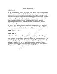
TITLE: Drainage, Better Drainage, and More Drainage ... - AREMA
TITLE: Drainage, Better Drainage, and More Drainage ... - AREMA

Create successful ePaper yourself
Turn your PDF publications into a flip-book with our unique Google optimized e-Paper software.
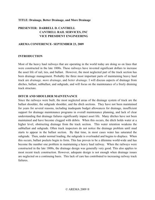
<strong>TITLE</strong>: <strong>Drainage</strong>, <strong>Better</strong> <strong>Drainage</strong>, <strong>and</strong> <strong>More</strong> <strong>Drainage</strong><br />
PRESENTER: DARRELL D. CANTRELL<br />
CANTRELL RAIL SERVICES, INC<br />
VICE PRESIDENT ENGINEERING<br />
<strong>AREMA</strong> CONFERENCE- SEPTEMBER 23, 2009<br />
INTRODUCTION<br />
Most of the heavy haul railways that are operating in the world today are doing so on lines that<br />
were constructed in the late 1800s. These railways have invested significant dollars to increase<br />
the asset life of rail, ties, <strong>and</strong> ballast. However, the most neglected part of the track section has<br />
been drainage management. Probably the three most important parts of maintaining heavy haul<br />
track are drainage, more drainage, <strong>and</strong> better drainage. I will discuss aspects of drainage from<br />
ditches, ballast, subballast, <strong>and</strong> subgrade, <strong>and</strong> will focus on the maintenance of a freely draining<br />
track structure.<br />
DITCH AND SHOULDER MAINTENANCE<br />
Since the railways were built, the most neglected areas of the drainage system of track are the<br />
ballast shoulder, the subgrade shoulder, <strong>and</strong> the ditch sections. They have not been maintained<br />
for years for several reasons, including inadequate budget allowances for drainage, insufficient<br />
support for drainage maintenance programs in overall maintenance planning, <strong>and</strong> lack of clear<br />
underst<strong>and</strong>ing that drainage failures significantly impact asset life. Many ditches have not been<br />
maintained <strong>and</strong> have become clogged with debris. When this occurs, the ditch holds water at a<br />
higher level, obstructing drainage from the track section. This water retention weakens the<br />
subballast <strong>and</strong> subgrade. Often track inspectors do not notice the drainage problem until mud<br />
starts to appear in the ballast section. By that time, in most cases water has saturated the<br />
subgrade. Then, under normal loading, the subgrade is overloaded <strong>and</strong> begins to displace. When<br />
this occurs, ballast pockets begin to form. This has proven to be a dilemma world-wide <strong>and</strong> has<br />
become the number one problem in maintaining a heavy haul railway. When the railways were<br />
constructed in the late 1800s, the drainage design was generally very good. This also applies to<br />
most recent track construction. However, adequate design is not enough when drainage issues<br />
are neglected on a continuing basis. This lack of care has contributed to increasing railway track<br />
failures.<br />
© <strong>AREMA</strong> 2009 ®
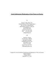
[Figure 1] Neglected drainage on Shoulder<br />
The photo illustrates a track segment where drainage management has been largely neglected.<br />
Twenty years ago when the track was built, most likely the proper drainage system was designed<br />
<strong>and</strong> constructed. Since that time, silt has run into the ditches <strong>and</strong> vegetation has also blocked the<br />
drainage. In addition, the ballast shoulder is extremely wide, <strong>and</strong> that also affects the drainage.<br />
Furthermore, since the shoulder is higher than the bottom of the tie, the track is left in a “bath<br />
tub” situation which causes the track section to remain saturated most of the time. When this<br />
occurs, the ballast breaks down more quickly <strong>and</strong> the resultant residue fouls the ballast section.<br />
It will not be long before the subgrade becomes saturated <strong>and</strong> starts to move, initiating shear.<br />
© <strong>AREMA</strong> 2009 ®
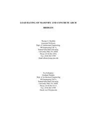
[Figure 2] Subgrade Shear<br />
This photo shows typical subgrade shear. Also, the ballast section is greatly fouled, restricting it<br />
from draining. When the ballast section cannot drain, the subballast or top formation becomes<br />
saturated <strong>and</strong> the subgrade displacement occurs. Also of concern is the fact that the ballast<br />
formation is beginning to shift. During heavy rains, the ballast pocket holds water <strong>and</strong> continues<br />
to get deeper when the track is loaded. Another major problem on heavy haul railways is that<br />
there is often insufficient ballast under the ties.<br />
RECOMMENDED CORRECTION OF<br />
INFERIOR DRAINAGE OUTSIDE THE TRACK SECTION<br />
It is highly recommended that the drainage system as originally designed <strong>and</strong> constructed be<br />
maintained. Likewise, it is very important that any vegetation on the subgrade shoulder be<br />
controlled, since it hinders proper drainage. Over time, the shoulders get higher <strong>and</strong> further<br />
block the drainage. The same thing occurs with vegetation in the ditch sections, causing them to<br />
silt in <strong>and</strong> restrict the water runoff.<br />
© <strong>AREMA</strong> 2009 ®
It is very important that the shoulders are kept sloped so the water will drain away from the<br />
track. This can be accomplished with a variety of mechanized equipment. One such machine,<br />
the Jordan Spreader, is popular in the USA, because it does a high-quality job of maintaining the<br />
proper shoulder. To provide proper drainage, the subgrade should fall a minimum of 100 mm (4<br />
in) from the toe of the ballast section to the outside edge of the subgrade shoulder. If the slope<br />
is too steep, the shoulder will start to erode. Where there is adequate width, a motor grader can<br />
be used to maintain the shoulders as well. It is common practice to use the shoulder as a<br />
maintenance roadway alongside the track. While the roadway is important in accessing the track<br />
to perform maintenance activities, it is very important to keep the roadway sloped away from the<br />
track so that the water will not run back into the track section.<br />
There are various pieces of equipment, such as the Badger ditcher <strong>and</strong> slot train that can be used<br />
to maintain the ditch line <strong>and</strong> grade for proper drainage. It is recommended that all ditches be<br />
maintained so the water will flow away from the track. However, in heavy haul operations, it is<br />
difficult to gain track occupancy in order to operate on-track equipment. In these cases, off-track<br />
equipment like grade-alls <strong>and</strong> excavators can be used to maintain the proper flow. If the proper<br />
drainage outside the ballast section is maintained, most track section drainage problems are<br />
eliminated. Remember, when performing a track inspection, the primary focus must be<br />
drainage, more drainage, <strong>and</strong> better drainage.<br />
SURFACE DRAINAGE<br />
Collecting <strong>and</strong> diverting surface water away from the track structure may be the most costeffective<br />
portion of any subgrade maintenance program. The more water that is intercepted <strong>and</strong><br />
diverted away from the track, the less water available to infiltrate <strong>and</strong> potentially weaken the<br />
track structure.<br />
Recommended maintenance practices include:<br />
• Improve surface drainage – make sure runoff runs off <strong>and</strong> does not pond.<br />
• Divert surface water prior to it reaching problem area.<br />
• Keep surface water as surface water. Do not let it pond or infiltrate the embankment or<br />
ground upslope of the embankment.<br />
• Deepen ditches to 305 mm (12 inches) below the bottom of the subballast (do not over<br />
deepen ditches such that support is lost for the track section).<br />
• Grade ditch bottoms to improve runoff.<br />
• Clean ditches <strong>and</strong> culverts.<br />
© <strong>AREMA</strong> 2009 ®
• Check culverts <strong>and</strong> ensure they are in good condition, have not rusted through, <strong>and</strong> or pulled<br />
apart.<br />
• Replace culverts that are too small with culverts of adequate capacity<br />
• Maintain culvert inlets <strong>and</strong> install systems to reduce potential for the inlet to plug or for<br />
debris to wash into the culvert <strong>and</strong> plug it.<br />
• Remove from embankment shoulders any debris produced by maintenance activities such as<br />
undercutting, shoulder ballast cleaning, <strong>and</strong> ditch cleaning.<br />
• Grade shoulders to drain water over the side of the embankment without restricting the flow.<br />
Erosion protection measures may be required on the slope.<br />
A common misconception with construction of ditches is that deeper is better. This is not always<br />
the case. Ditching too close to the track section or embankments <strong>and</strong> digging too deep can cause<br />
undermining of the track or embankment failure. Care should be taken to properly construct the<br />
ditches so that the ditches serve to drain the track area, not adjacent fields. In some cases,<br />
installation of near-track subsurface drains is more appropriate.<br />
DRAINAGE OF BALLAST AND SUBBALLAST<br />
As mentioned earlier, in heavy haul operations, if the shoulders <strong>and</strong> ditches are properly drained,<br />
they will contribute to better drainage of the ballast <strong>and</strong> subballast. Ballast drainage has to be<br />
maintained to keep the proper resiliency under the tie. This area is affected when there is not<br />
sufficient ballast under the ties. With the heavy axle loads, the ballast breaks down <strong>and</strong> along<br />
with dirt blown into the ballast section, it becomes heavily fouled. Also, it is affected by<br />
improper tamping cycles for heavy haul operations. If the track loses its resiliency, it affects the<br />
asset life of rail, fasteners, ties, <strong>and</strong> ballast. In concrete tie tracks, if the ballast bed is not<br />
resilient, the ties will begin to crack or become center bound more quickly. When this occurs, it<br />
puts excessive force on the pads <strong>and</strong> fasteners. As it starts to affect the rail, spaulding <strong>and</strong><br />
surface cracks appear, reducing the life of the rail.<br />
Every railway has engineering st<strong>and</strong>ards relating to depths of ballast <strong>and</strong> shoulder ballast widths.<br />
A common st<strong>and</strong>ard requires that the ballast shoulder will be 305mm (12 in) wide from the end<br />
of the tie <strong>and</strong> either have a 1 1/2 to 1 or a 2 to 1 slope, although there are some exceptions on<br />
curves. Many heavy haul lines have excessive amounts of ballast on the shoulder. Instead of<br />
providing a benefit, excessive ballast restricts the drainage of the ballast section.<br />
In most heavy haul operations, the expected ballast life is 12 to 18 years. However, this does not<br />
mean that all ballast has to be removed at the end of its expected life. But it does mean that<br />
procedures for maintaining the ballast section must be employed. In order to preserve resiliency<br />
under the ties, the track must be surfaced on repeated cycles. The recommended cycles are more<br />
© <strong>AREMA</strong> 2009 ®
frequent on concrete than they are on wood. Maintenance programs involving shoulder ballast<br />
cleaning as well as full ballast bed cleaning should be planned as well. These cycles can fit well<br />
with the heavy haul ballast life recommendations. When concrete ties are initially placed on<br />
existing mainline track, it is recommended that the full ballast bed be cleaned. Then new ballast<br />
should be added until there is a recommended thickness of 254 to 305 mm (10 to 12 in) under the<br />
ties. It is further recommended that one year following concrete tie installation, the track is<br />
surfaced.<br />
In most heavy haul operations, it is very important to establish surfacing cycles based on gross<br />
tonnage. Tracks with concrete ties should be surfaced every 150 to 200 million gross tons of<br />
traffic. Tracks with wood ties should be surfaced every 200 to 250 million gross tons of traffic.<br />
This will promote resiliency <strong>and</strong> help maintain a high-quality, live ballast bed for the ties.<br />
FOULED BALLAST<br />
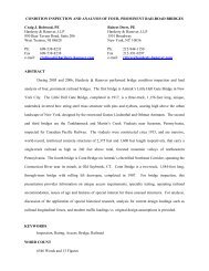
[Figure 3] Fouled Ballast<br />
In many locations, localized stretches of fouled ballast form in the track structure. Fouled ballast<br />
may be caused by a number of sources, including ballast breakdown, contamination by<br />
subballast or subgrade soils, <strong>and</strong> contamination by soils carried into the ballast by wind, water,<br />
© <strong>AREMA</strong> 2009 ®
vehicles crossing the track, materials dropped from train cars, or other sources. Except in heavy<br />
coal dust areas, ballast breakdown is generally the greatest contributor to fouled ballast<br />
conditions.<br />
Ballast breakdown often occurs under track locations where impact loading is most intense.<br />
Problems with impact loading in switches, particularly at the frog, are common. Railhead<br />
imperfections like engine burns <strong>and</strong> battered joints may also cause impact loading under traffic.<br />
Impact loading can lead to accelerated ballast breakdown <strong>and</strong> fouling of the ballast. Fouled<br />
ballast <strong>and</strong> shoulder fouling lead to water retention in the track structure. As the crushing <strong>and</strong><br />
grinding of ballast particles under traffic progresses, drainage from the track structure is<br />
impaired. The water retained in the ballast as a result of this impaired drainage accelerates the<br />
ballast breakdown process. Ballast failure <strong>and</strong> the mud pumping associated with it may cause<br />
loss of tie support.<br />
Traditional maintenance methods such as undercutting <strong>and</strong> shoulder cleaning should generally be<br />
employed to clean <strong>and</strong> replace ballast fouled as a result of ballast breakdown. However, if the<br />
fouling is localized, shallow trench drains cut perpendicular to the track section <strong>and</strong> at relatively<br />
close spacing may be a cost effective temporary means of improving an otherwise deteriorating<br />
situation.<br />
Ballast contamination can also occur as a result of pumping of sub-grade soils into the ballast or<br />
pushing of ballast into the sub-grade. These situations most commonly occur in areas with lack<br />
of a suitable subballast layer.<br />
[Figure 4] Subgrade Pumping<br />
© <strong>AREMA</strong> 2009 ®
BALLAST MAINTENANCE ACTIVITIES TO INCREASE BALLAST DRAINAGE<br />
An out-of-face surfacing cycle should be established based on gross tonnage. Tracks with<br />
concrete ties should be surfaced out-of-face every 150 to 200 million gross tons <strong>and</strong> those with<br />
wood ties every 200 to 250 million gross tons. This will promote resiliency <strong>and</strong> help to maintain<br />
a high-quality, live ballast bed for the ties. Where there are concrete ties, it is recommended that<br />
the ballast shoulder be cleaned every other out-of-face surfacing cycle. On wood tie track, run<br />
the shoulder ballast cleaner in advance of wood tie renewals, <strong>and</strong> then every three to four years<br />
following the tie installations.<br />
Assuming the service life of ballast is approximately 12 to 18 years; the full ballast section<br />
should be undercut <strong>and</strong> cleaned every 12 years on concrete tie track. This schedule should keep<br />
the ballast bed clean <strong>and</strong> allow the ties to attain their expected life. It is suggested that wood tie<br />
track in heavy haul operations be undercut <strong>and</strong> cleaned every 15 to 18 years. This will help<br />
maintain the proper ballast drainage <strong>and</strong> extend the life of the wood ties. It is likely that with the<br />
continued increase of axle loads, more railways will enlist the use of subgrade rehabilitation<br />
machines similar to those used in Europe <strong>and</strong> China.<br />
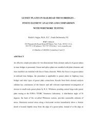
[Figure 5] Subgrade Rehabilitatin<br />
© <strong>AREMA</strong> 2009 ®
The photo shows track that was rehabbed in 1999 in Austria with the AHM 800 subgrade<br />
rehabilitation machine. The different strata layers in the cross section are obvious: The good<br />
ballast section, the protective layer, the geotechnical fabric, <strong>and</strong> the subgrade. The purpose for<br />
cutting the track was in connection with a line change. Note that the subgrade is losing its shape,<br />
but the top of the subballast is not. This particular segment of track has had 1.6 billion gross tons<br />
of traffic since it was rehabbed. There are locations in Europe that were rehabilitated in the mid-<br />
80’s.<br />
SUBSTRUCTURE DRAINAGE<br />
Before failing track areas can be effectively treated, the cause or primary contributors to the track<br />
condition should be identified. This is sometimes easier said than done. As stated previously,<br />
water is a primary factor in most unstable track situations. However, while water may not have<br />
been the initial cause of a particular situation, the development of the instability generally leads<br />
to the retention of water, which accelerates the problem.<br />
Before water can be drained, potential sources of water must be identified. In general, there are<br />
four principal sources of water to consider:<br />
• Rainfall or snowmelt directly on the track structure<br />
• Surface water flowing toward <strong>and</strong> infiltrating the track structure<br />
• Water flowing within the track structure, e.g., within ballast pockets or fill used to construct<br />
the embankment<br />
• Groundwater<br />
Techniques used to reduce infiltration when constructing new track include sloping the upper<br />
surface of the subgrade <strong>and</strong> subballast, placement of clean ballast, construction of ditches below<br />
the bottom of the subballast, <strong>and</strong> shaping embankment shoulders so that water flows away from<br />
the track. Periodically regrading the top of the subgrade <strong>and</strong> subballast is not a practical track<br />
maintenance operation. However, ballast <strong>and</strong> embankment drainage are areas that can be<br />
addressed by maintenance programs. Maintenance personnel can make a difference by:<br />
• Maintaining ditch bottoms at least 305 mm (12 in) below the bottom of subballast<br />
• Keeping ditches clean <strong>and</strong> properly graded<br />
Keeping embankment shoulders clean <strong>and</strong> sloped to drain<br />
© <strong>AREMA</strong> 2009 ®
TRACK SUBSURFACE DRAINAGE<br />
Excluding erosion by surface waters, water generally causes the most problems after it infiltrates<br />
railroad embankments <strong>and</strong> track structures. Water in the soil <strong>and</strong> in cracks that have opened in<br />
the ground can destabilize embankments or decrease soil strength. This water is often a major<br />
contributor to track failure conditions. Draining this water from the track section <strong>and</strong><br />
embankment is fundamental to improving track <strong>and</strong> embankment performance.<br />
Water tends to accumulate in track locations where the drainage is impaired such as road<br />
crossing approaches, bridge approaches, low points in vertical curves, <strong>and</strong> at other locations<br />
where track settlement has occurred <strong>and</strong> the track has been raised on additional ballast.<br />
Typical places within an embankment where water may be expected to accumulate or become<br />
trapped, <strong>and</strong> from which it should be drained, include:<br />
• Ballast pockets<br />
• Cracks in embankments<br />
• At the contact between the subgrade <strong>and</strong> a relatively rigid slab that overlies the subgrade, but<br />
below the ballast.<br />
• At the contact of more permeable rock or soil with less permeable materials.<br />
A method commonly employed to drain water from track sections <strong>and</strong><br />
embankments is to construct gravel-filled trench drains.<br />
NON-TRACK GROUNDWATER INTERCEPTION AND DRAINAGE<br />
Groundwater in soils below embankments, flowing toward embankments from upslope areas, or<br />
flowing toward track constructed in cuts can lead also to unstable track conditions. Interception<br />
<strong>and</strong> removal of this water <strong>and</strong> lowering of the water table to a satisfactory depth below the<br />
embankment or track substructure may improve the performance of embankments <strong>and</strong> track<br />
sections. Collection <strong>and</strong> removal of this groundwater may also improve stability of the slope<br />
through which the water is flowing, whether located above or below the track.<br />
Some indicators of high groundwater conditions are:<br />
• The presence of springs on slopes above or below the track<br />
• Ground that is wet even during extended dry periods<br />
• Vegetation normally associated with wetl<strong>and</strong>s growing on nearby slopes<br />
• Green vegetation growing in ditches or on slopes during dry times of the year, especially in<br />
regions of the country with dry climates.<br />
© <strong>AREMA</strong> 2009 ®
Gravel-filled trench drains may be constructed to intercept <strong>and</strong> drain near-surface groundwater<br />
flowing toward the track. These drains may be constructed parallel to <strong>and</strong> relatively near the<br />
track or at some distance upslope from the track. Shallow drains with pipes are sometimes<br />
installed parallel <strong>and</strong> near the track to improve subgrade performance. The most effective <strong>and</strong><br />
most practical location to install trench drains to intercept off-alignment groundwater depends on<br />
a number of factors, including the source of the water, depth, site topography, site geology,<br />
access considerations, <strong>and</strong> property ownership. In the vast majority of situations, a geotechnical<br />
professional should be consulted to assist with locating <strong>and</strong> installation of these trench drains.<br />
Depending on the groundwater depth, topography, <strong>and</strong> geology, other drainage systems may be<br />
required. Horizontal drains, small diameter perforated pipes installed in holes drilled into the<br />
ground, are one common alternative. The holes are drilled at a slight upward inclination so that<br />
water that infiltrates the pipe will flow to the pipe outlet at the slope face. This technique gained<br />
wide acceptance along some railways for l<strong>and</strong>slide stabilization in some locations of the USA<br />
during the 1960s <strong>and</strong> 1970s. The assistance of a geotechnical professional is recommended for<br />
horizontal drain applications.<br />
High groundwater conditions <strong>and</strong> springs are also common contributors to l<strong>and</strong>slides. In<br />
l<strong>and</strong>slide susceptible terrain, trench drains, horizontal drains, or other subsurface drainage<br />
methods may be components of a l<strong>and</strong>slide stabilization program. However, because many<br />
factors may affect ground instability, the assistance of a geotechnical professional is<br />
recommended.<br />
© <strong>AREMA</strong> 2009 ®