
You also want an ePaper? Increase the reach of your titles
YUMPU automatically turns print PDFs into web optimized ePapers that Google loves.
1<br />
<strong>LCLS</strong>-<strong>TN</strong>-<strong>02</strong>-4<br />
7 December 2001<br />
Revised 14 July 20<strong>02</strong><br />
Maximum Beam Power and Nominal Beam Losses at S-20<br />
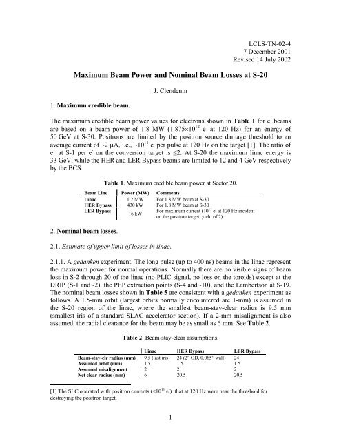
1. Maximum credible beam.<br />
J. Clendenin<br />
The maximum credible beam power values for electrons shown in Table 1 for e - beams<br />
are based on a beam power of 1.8 MW (1.87510 12 e - at 120 Hz) for an energy of<br />
50 GeV at S-30. Positrons are limited by the positron source damage threshold to an<br />
average current of ~2 A, i.e., ~10 11 e - per pulse at 120 Hz on the target [1]. The ratio of<br />
e + at S-1 per e - on the conversion target is ≤2. At S-20 the maximum linac energy is<br />
33 GeV, while the HER and LER Bypass beams are limited to 12 and 4 GeV respectively<br />
by the BCS.<br />
Table 1. Maximum credible beam power at Sector 20.<br />
Beam Line Power (MW) Comments<br />
Linac 1.2 MW For 1.8 MW beam at S-30<br />
HER Bypass 430 kW For 1.8 MW beam at S-30<br />
LER Bypass<br />
16 kW<br />
For maximum current (10 11 e - at 120 Hz incident<br />
on the positron target, yield of 2)<br />
2. Nominal beam losses.<br />
2.1. Estimate of upper limit of losses in linac.<br />
2.1.1. A gedanken experiment. The long pulse (up to 400 ns) beams in the linac represent<br />
the maximum power for normal operations. Normally there are no visible signs of beam<br />
loss in S-2 through 20 of the linac (no PLIC signal, no loss on the toroids) except at the<br />
DRIP (S-1 and -2), the PEP extraction points (S-4 and -10), and the Lambertson at S-19.<br />
The nominal beam losses shown in Table 5 are consistent with a gedanken experiment as<br />
follows. A 1.5-mm orbit (largest orbits normally encountered are 1-mm) is assumed in<br />
the S-20 region of the linac, where the smallest beam-stay-clear radius is 9.5 mm<br />
(smallest iris of a standard SLAC accelerator section). If a 2-mm misalignment is also<br />
assumed, the radial clearance for the beam may be as small as 6 mm. See Table 2.<br />
Table 2. Beam-stay-clear assumptions.<br />
Linac HER Bypass LER Bypass<br />
Beam-stay-clr radius (mm) 9.5 (last iris) 24 (2” OD, 0.065” wall) 24<br />
Assumed orbit (mm) 1.5 1.5 1.5<br />
Assumed misalignment 2 2 2<br />
Net clear radius (mm) 6 20.5 20.5<br />
[1] The SLC operated with positron currents (
The methodology adopted here is to choose a beam size that is realistic, then calculate the<br />
expected beam loss based on a simple model of the charge distribution in the beam.<br />
The lattice is designed for =50 m, and the projected, measured, normalized rms<br />
emittance for the long pulse beam is n=2010 -5 m. This yields 0.<br />
4 mm at S-<br />
20 (=610 4 ). There are at least two ways a larger could occur. If there is a factor of f<br />
-mismatch, or if n grows by f (which might be due to large tails), or if there is the<br />
appropriate combination of these two, then will be larger. A value of f=8 is chosen,<br />
resulting in a value of =1.2 mm.<br />
If the spatial distribution of particles in the beam is assumed to be Gaussian with an rms<br />
radius of , then the fraction, F, of beam outside n can be approximated by<br />
2 <br />
<br />
1<br />
1<br />
2<br />
<br />
<br />
n<br />
e<br />
2<br />
1<br />
2<br />
<br />
<br />
<br />
<br />
F . (1)<br />
Values of F for various values of n are compiled in Table 3 using Eq. (1).<br />
Table 3. Interpretation of Eq. (1).<br />
n 0 1 2 3 4 5 6 <br />
F 1 3.710 -1<br />
710 -2<br />
5.610 -3<br />
1.710 -4<br />
1.910 -6<br />
7.610 -9 0<br />
For a of 1.2 mm and radial clearance of 6 mm, n~5.2, which by Eq. (1) implies<br />
F~6.710 -7 . Thus for a 600 kW beam [2], a loss of 0.4 W is expected.<br />
The upper limit on the nominal loss for high-intensity long-pulse beams at section 20-8C<br />
(at 33 GeV) is estimated to be 610 5 e - per pulse (0.4 W at 120 Hz).<br />
2.1.2. Comparison with PLIC. At 33 GeV, a loss of 0.4 W at 120 Hz corresponds to<br />
~610 5 e - per pulse. If one assumes that this loss is the type described by the gedanken<br />
experiment above and that it repeats itself at the output coupler of each 3-m section, then<br />
the loss in the S-20 area should be no more than ~210 5 e - per m, 610 5 e - per 3-m<br />
section, or 210 7 e - per pulse for all of S-20. Can such a loss be detected by the PLIC?<br />
For a high-intensity long-pulse beam, no PLIC signal above noise can be seen at Sector<br />
20. In Fig. 1, the only discrete losses that can be seen are a 20 mV peak at the S-1<br />
[2] For a beam of 1×10 12 e - at 120 Hz, the beam power at 33 GeV is ~600 kW.
chicane (early in S-1) and also at the DRIP (end of S-1, beginning of S-2), a 3 mV peak<br />
at S-4, 2 mV at S-10, and 8 mV at the S-19 Lambertson, and then a small loss at about S-<br />
25. (There is evidence on the S-19 pulse of a shoulder at ~2.5 mV that is located very<br />
close to S-20.) The discrete losses are characterized by a relatively fast risetime followed<br />
by a slower tail. The FWHM of a discrete PLIC pulse for the long-pulse beam is about<br />
600 ns, which also corresponds to about 1 sector or 100 m. The height of the PLIC noise<br />
is no more than 2 mV. A 2 mV discrete pulse every 100 m will appear to be a fairly<br />
uniform 2 mV signal. Thus the noise can be considered equivalent to a maximum<br />
uniform loss of 0.<strong>02</strong> mV per m.<br />
Fig. 1. Linac PLIC signal on Jan. 16, 20<strong>02</strong>, at 11:36 for a bunch of 610 11 e - with a bunch length<br />
of 320 ns. (eoicdesk pc: P1161136.jpg). The units are 5 mV/cm and 2 s/cm for the vertical and<br />
horizontal axes respectively. Photo by Paul Miller.<br />
Recently the PLIC signal for a 28 GeV beam was variously calibrated to be 4.710 6 e - per<br />
mV (Paul Miller directed a known beam intensity into the ST960 stopper [3]) or 510 7 e -<br />
per mV (Mike Stanek scrapped the tails of the beam by a known amount using the<br />
moveable collimator at 29-1 [4]). Thus the PLIC noise corresponds to an upper limit on a<br />
uniform loss of 10 5 to 10 6 e - per m or 310 5 to 310 6 e - per 3-m section (0.19 to 1.9 W<br />
per section at 120 Hz and 33 GeV).<br />
At the suggestion of Marc Ross, the raw PLIC signal was examined. This increases the<br />
PLIC sensitivity by about an order of magnitude. The results are shown in Fig. 2. Due to<br />
the change in the scope scale, the S-19 signal now appears just to the right of the scope<br />
center and is 108 mV, a factor of 13.5 greater than in Fig. 1. The noise is ~10 mV or only<br />
a factor of ~5 greater than in Fig. 1. The noise in Fig. 2 implies the upper limit on a<br />
uniform loss derived from Fig. 1 should be a factor of 2 lower, corresponding to a loss of<br />
[3] M. Saleski email to J. Clendenin, Jan. 23, 20<strong>02</strong>, 4:34 PM.<br />
[4] M. Stanek email to R. Nelson, Oct. 22, 2001, 12:18:54.<br />
3
0.1 to 1 W per 3-m section at 120 Hz and 33 GeV. The shoulder at S-20, if it represents<br />
real beam loss, would add another 0.1 to 1 W for the entire sector.<br />
Thus the upper limit on the loss predicted in section 2.1.1 (610 5 e - in a 3-m section) is<br />
consistent with the observed PLIC signal for a high-intensity long-pulse linac beam.<br />
Fig. 2. Raw linac PLIC signal on Feb. 25, 20<strong>02</strong>, at about 09:55 for a bunch of 5.9×10 11 e - . The<br />
units are 50 mV/cm and 4 s/cm. Photo by Paul Miller.<br />
2.1.3. Comparison with the “1% rule.” The loss per section derived from the gedanken<br />
experiment is less than 4% of the 10-W loss per section assumed by the traditional “1%<br />
rule” for losses in the linac [5]. The 1% rule assumes uniform losses along the linac,<br />
whereas most of the losses should occur at the low-energy end when the beam size is<br />
larger.<br />
2.2. Nominal losses in HER and LER Bypass lines.<br />
There are likewise no visible signs of beam loss in the HER/LER Bypass lines. The linac<br />
beam is monitored fairly carefully, so the losses due to large orbits, mismatch, and<br />
emittance growth are minimal. However, the HER/LER Bypass lines are not so closely<br />
monitored. To account for this situation, the beta mismatch factor in the Bypass lines is<br />
assumed to be 50% larger than in the linac, i.e., f=12 is assumed. This leads to =3.2 mm<br />
in the HER Bypass. See Table 4. The beam pipe has an inner radius of 24 mm. Again<br />
assuming a 1.5 mm orbit and 2 mm misalignment, the radial clearance for the beam may<br />
[5] For a beam of 1×10 12 e - at 120 Hz, the beam power at 50 GeV is ~1 MW, 1% of which is 10 kW.<br />
Assuming a uniform loss along the linac, this corresponds to 10 W per 3-m section.<br />
4
e as low as 20.5 mm. See Table 2. Consequently, n=6.4 and the expected losses are 10 -6<br />
W.<br />
On the other hand, in the LER Bypass the positron beam size for the same conditions as<br />
in HER, because of the lower energy, is significantly larger, i.e., =5.9 mm. Then the<br />
vacuum pipe is only 3.5 away, thus F~10 -3 . For a nominal beam power of 1.5 kW, this<br />
is a loss of 1.5 W.<br />
Table 4. Comparison of Linac and HER /LER Bypass beams.<br />
Design<br />
(m)<br />
Linac 50 8 2010 -5<br />
HER Bypass 350 12 510 -5<br />
LER Bypass 350 12 510 -5<br />
2.3. Summary.<br />
f n (m) (mm) n Nominal S-20<br />
beam power<br />
5<br />
Nominal<br />
S-20 beam<br />
loss<br />
610 4 1.15 5.2 600 kW [2] (120 Hz) 0.4 W<br />
210 4 3.2 6.4 5 kW (60 Hz) 1 W<br />
610 3 5.9 3.5 1.5 kW (60 Hz) 1.5 W<br />
The upper limit for the nominal beam losses expected at Sector 20 are summarized in<br />
Table 5.<br />
Table 5. Summary of beam losses at Sector 20 for corresponding nominal beam power.<br />
Beam Line Beam loss (W) Corresponding nominal beam power<br />
Linac 0.4 1×10 12 e - at 33 GeV and 120 Hz→600 kW<br />
HER Bypass 10 -6<br />
4×10 10 e - at 12 GeV and 60 Hz→5 kW<br />
LER Bypass 1.5 4×10 10 e - at 4 GeV and 60 Hz→1.5 kW<br />
Acknowledgements: F.-J. Decker suggested many of the scenarios discussed here. Paul Miller<br />
organized the PLIC measurements for the high power linac beam. Mike Saleski contributed many<br />
useful comments.
From: Saleski, E. Michael<br />
Sent: Wednesday, January 23, 20<strong>02</strong> 4:34 PM<br />
To: Clendenin, James<br />
Cc: Miller, Paul; Stanek, Michael; Nelson, W. Ralph; Prinz, Alyssa A.<br />
Subject: Loss Estimate using PLIC<br />
Jim,<br />
Unfortunately, I don't think that PLIC has enough resolution for your<br />
needs. You want to claim/verify that the average loss from the main linac<br />
is 0.4W in the vicinity of the <strong>LCLS</strong> injector. This is average power, and PLIC<br />
looks at power/pulse; in other words, it is repetition rate independent. So,<br />
assuming 120Hz rep rate for the 0.4W loss, that gives us 7.3e5 particles/pulse<br />
that we are trying to verify is the normal loss for the beam in that region.<br />
Paul's December ST950 and ST960 calibrations also gave us fiducials for the PLIC.<br />
He ran 2e10 electrons/pulse at 28.5 GeV into the stoppers (90W at 1Hz) and the<br />
PLIC signal achieved 3.0V and 4.25V for stoppers 950 and 960, respectively.<br />
Let's consider ST960's 4.25V, as it turns out that sensitive PLIC would be<br />
favorable for this measurement. Also, let's forget about scaling the PLIC readings<br />
with energy and assume that the Linac beam will be at 28.5 GeV as it passes the<br />
<strong>LCLS</strong> injector; it's a close enough approximation. So the ST960 PLIC signal corresponds<br />
to 4.7e6 electrons/mV of PLIC signal. Also, I spoke with Mike Stanek, and he told me<br />
that he found a 10 mV PLIC reading with 5e8 electrons as best estimated with<br />
torroids for beam loss with the sector 30 collimators (also at 28.5 GeV); this is<br />
5e7 electrons/mV of PLIC signal.<br />
Now, to find 7.3e5 particles on the PLIC scope, I need to look for 0.11mV signal<br />
(Paul's calibration) or a 0.015mV signal (Stanek's calibration). When I go look<br />
at the PLIC scope, I observe that there is 1mV or more of noise! We can't measure<br />
better than 1e7 electrons (plus or minus, depending which calibration you<br />
believe), which is unfortunate.<br />
However, I do remember some years ago when I was a new OP at MCC and Marc Ross<br />
actually found a kimwipe left in the beampipe using PLIC (we knew that something<br />
was blowing up the emittance). It seems to me that a kimwipe would cause less<br />
than 1e7 electrons/pulse loss. I would talk to Marc Ross on this one. Regardless,<br />
he would be an excellent source of estimating the losses along the linac, and<br />
he's a member of the RSC, so he'll certainly carefully scrutinize your estimation<br />
eventually, anyway.<br />
As far as the old OPS at most 1% is lost, the '1% rule,' goes... If we assume that<br />
normal beam loss occurs on the smallest aperture on each accelerating structure, as<br />
designed, we find that just over 1e-3 of the loss occurs at each structure (about<br />
950 structures), or 1e-5 of the beam is lost at each structure (an order of magnitude<br />
6
larger than you assertion). This 1e-5 agrees with the PLIC limit: If we consider<br />
a 6.5e11 p/p beam (the 550kW E158 beam), then 1e-5 loss at each accelerator structure<br />
is 6.5e6 p/p. This is just at the limit of the sensitivity of the PLIC system; we may<br />
or may not be able to see this. That's probably where the 1% rule came from.<br />
Nonetheless, I will only be able to confirm that normal beam loss does not exceed 1%<br />
with PLIC. For <strong>LCLS</strong>, you really need to demonstrate that you meet the 0.1% rule,<br />
it seems.<br />
Mike Saleski<br />
7
Date: Mon, 22 Oct 2001 12:18:54 -0700<br />
From: "Stanek, Michael" <br />
To: "Nelson, W. Ralph" <br />
Subject: Possible beam power loss at 20-9<br />
Ralph,<br />
I did some experiments with the present beam in the Linac on Friday,<br />
and came up with the estimate below.<br />
I tried to mis-steer a ~28 GeV beam at 20-9, and was not able to<br />
generate any PLIC signal or noticeble beam loss with dipoles in that<br />
viscinity. I was able to make some loss further downstream, probably<br />
at ~25-9, with a several mm oscillation starting in Sector 20. If I<br />
were to interrupt the PEP beams, I could probably generate loss at 20-9<br />
by steering upstream of the Scavenger line. I was not able to do that<br />
last week.<br />
So to get a more controlled estimate, I used the moveable collimator<br />
at 29-1, and scraped the beam tails until I measured a PLIC signal ~10%<br />
of the trip threshold (10 mV, and rate limit starts at 100 mV). This<br />
should replicate an E158 "possible" beam loss at 20-9 that might<br />
persist for some time. I doubt if normal beam tuning would result in<br />
this condition, but it is possible.<br />
The measured beam loss for this 10 mV PLIC signal at 28 GeV is ~5e8<br />
e-/pulse. Projecting this to 120 pulses/sec gives a beam power loss of<br />
~270 Watts.<br />
I hope this is what you are looking for. If you have any questions,<br />
let me know.<br />
Michael Stanek<br />
stanek@slac.stanford.edu<br />
SLAC - phone (650)926-4340<br />
home - (408)255-2311<br />
8