Arbitrary waveform generator & function
Arbitrary waveform generator & function
Arbitrary waveform generator & function

Create successful ePaper yourself
Turn your PDF publications into a flip-book with our unique Google optimized e-Paper software.
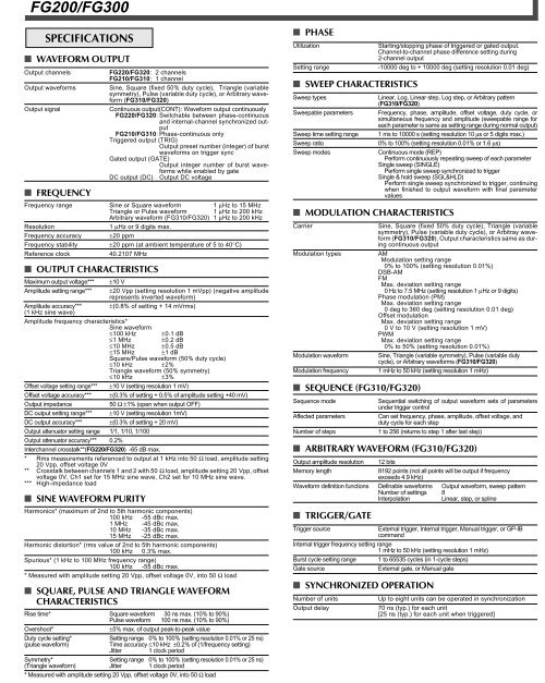
FG200/FG300<br />
SPECIFICATIONS<br />
■ WAVEFORM OUTPUT<br />
Output channels FG220/FG320: 2 channels<br />
FG210/FG310: 1 channel<br />
Output <strong>waveform</strong>s Sine, Square (fixed 50% duty cycle), Triangle (variable<br />
symmetry), Pulse (variable duty cycle), or <strong>Arbitrary</strong> <strong>waveform</strong><br />
(FG310/FG320)<br />
Output signal Continuous output(CONT): Waveform output continuously<br />
FG220/FG320: Switchable between phase-continuous<br />
and internal-channel synchronized output<br />
FG210/FG310: Phase-continuous only<br />
Triggered output (TRIG)<br />
Output preset number (integer) of burst<br />
<strong>waveform</strong>s on trigger sync<br />
Gated output (GATE)<br />
Output integer number of burst <strong>waveform</strong>s<br />
while enabled by gate<br />
DC output (DC) Output DC voltage<br />
■ FREQUENCY<br />
Frequency range Sine or Square <strong>waveform</strong> 1 μHz to 15 MHz<br />
Triangle or Pulse <strong>waveform</strong> 1 μHz to 200 kHz<br />
<strong>Arbitrary</strong> <strong>waveform</strong> (FG310/FG320) 1 μHz to 200 kHz<br />
Resolution 1 μHz or 9 digits max.<br />
Frequency accuracy ±20 ppm<br />
Frequency stability ±20 ppm (at ambient temperature of 5 to 40°C)<br />
Reference clock 40.2107 MHz<br />
■ OUTPUT CHARACTERISTICS<br />
Maximum output voltage*** ±10 V<br />
Amplitude setting range*** ±20 Vpp (setting resolution 1 mVpp) (negative amplitude<br />
represents inverted <strong>waveform</strong>)<br />
Amplitude accuracy*** ±(0.8% of setting + 14 mVrms)<br />
(1 kHz sine wave)<br />
Amplitude frequency characteristics*<br />
Sine <strong>waveform</strong><br />
≤100 kHz ±0.1 dB<br />
≤1 MHz ±0.2 dB<br />
≤10 MHz ±0.5 dB<br />
≤15 MHz ±1 dB<br />
Square/Pulse <strong>waveform</strong> (50% duty cycle)<br />
≤10 kHz ±2%<br />
Triangle <strong>waveform</strong> (50% symmetry)<br />
≤10 kHz ±3%<br />
Offset voltage setting range*** ±10 V (setting resolution 1 mV)<br />
Offset voltage accuracy*** ±(0.3% of setting + 0.5% of amplitude setting +40 mV)<br />
Output impedance 50 Ω ±1% (open when output OFF)<br />
DC output setting range*** ±10 V (setting resolution 1mV)<br />
DC output accuracy*** ±(0.3% of setting + 20 mV)<br />
Output attenuator setting range 1/1, 1/10, 1/100<br />
Output attenuator accuracy*** 0.2%<br />
Interchannel crosstalk**(FG220/FG320) -65 dB max.<br />
* Rms measurements referenced to output at 1 kHz into 50 Ω load, amplitude setting<br />
20 Vpp, offset voltage 0V<br />
** Crosstalk between channels 1 and 2 with 50 Ω load, amplitude setting 20 Vpp, offset<br />
voltage 0V, Ch1 set for 15 MHz sine wave, Ch2 set for 10 MHz sine wave.<br />
*** High-impedance load<br />
■ SINE WAVEFORM PURITY<br />
Harmonics* (maximum of 2nd to 5th harmonic components)<br />
100 kHz -55 dBc max.<br />
1 MHz -45 dBc max.<br />
10 MHz -35 dBc max.<br />
15 MHz -25 dBc max.<br />
Harmonic distortion* (rms value of 2nd to 5th harmonic components)<br />
100 kHz 0.3% max.<br />
Spurious* (1 kHz to 100 MHz frequency range)<br />
100 kHz -55 dBc max.<br />
* Measured with amplitude setting 20 Vpp, offset voltage 0V, into 50 Ω load<br />
■ SQUARE, PULSE AND TRIANGLE WAVEFORM<br />
CHARACTERISTICS<br />
Rise time* Square <strong>waveform</strong> 030 ns max. (10% to 90%)<br />
Pulse <strong>waveform</strong> 100 ns max. (10% to 90%)<br />
Overshoot* ±5% max. of output peak-to-peak value<br />
Duty cycle setting* Setting range 0% to 100% (setting resolution 0.01% or 25 ns)<br />
(pulse <strong>waveform</strong>) Time accuracy ≤10 kHz ±0.2% of (1/frequency setting)<br />
Jitter 1 clock period<br />
Symmetry* Setting range 0% to 100% (setting resolution 0.01% or 25 ns)<br />
(Triangle <strong>waveform</strong>) Jitter 1 clock period<br />
* Measured with amplitude setting 20 Vpp, offset voltage 0V, into 50 Ω load<br />
■ PHASE<br />
Utilization Starting/stopping phase of triggered or gated output.<br />
Channel-to-channel phase difference setting during<br />
2-channel output<br />
Setting range -10000 deg to + 10000 deg (setting resolution 0.01 deg)<br />
■ SWEEP CHARACTERISTICS<br />
Sweep types Linear, Log, Linear step, Log step, or <strong>Arbitrary</strong> pattern<br />
(FG310/FG320)<br />
Sweepable parameters Frequency, phase, amplitude, offset voltage, duty cycle, or<br />
simultaneous frequency and amplitude (sweepable range for<br />
each parameter is same as setting range during normal output)<br />
Sweep time setting range 1 ms to 10000 s (setting resolution 10 μs or 5 digits max.)<br />
Sweep ratio 0% to 100% (setting resolution 0.01% or 1.6 μs)<br />
Sweep modes Continuous mode (REP)<br />
Perform continuously repeating sweep of each parameter<br />
Single sweep (SINGLE)<br />
Perform single sweep synchronized to trigger<br />
Single & hold sweep (SGL&HLD)<br />
Perform single sweep synchronized to trigger, continuing<br />
when finished to output <strong>waveform</strong> with final parameter<br />
values<br />
■ MODULATION CHARACTERISTICS<br />
Carrier Sine, Square (fixed 50% duty cycle), Triangle (variable<br />
symmetry), Pulse (variable duty cycle), or Arbitray <strong>waveform</strong><br />
(FG310/FG320), Output characteristics same as during<br />
continuous output<br />
Modulation types AM<br />
Modulation setting range<br />
0% to 100% (setting resolution 0.01%)<br />
DSB-AM<br />
FM<br />
Max. deviation setting range<br />
0 Hz to 7.5 MHz (setting resolution 1 μHz or 9 digits)<br />
Phase modulation (PM)<br />
Max. deviation setting range<br />
0 deg to 360 deg (setting resolution 0.01 deg)<br />
Offset modulation<br />
Max. deviation setting range<br />
0 V to 10 V (setting resolution 1 mV)<br />
PWM<br />
Max. deviation setting range<br />
0% to 50% (setting resolution 0.01%)<br />
Modulation <strong>waveform</strong> Sine, Triangle (variable symmetry), Pulse (variable duty<br />
cycle), or <strong>Arbitrary</strong> <strong>waveform</strong>s (FG310/FG320)<br />
Modulation frequency 1 mHz to 50 kHz (setting resolution 1 mHz)<br />
■ SEQUENCE (FG310/FG320)<br />
Sequence mode Sequential switching of output <strong>waveform</strong> sets of parameters<br />
under trigger control<br />
Affected parameters Can set frequency, phase, amplitude, offset voltage, and<br />
duty cycle for each step<br />
Number of steps 1 to 256 (returns to step 1 after last step)<br />
■ ARBITRARY WAVEFORM (FG310/FG320)<br />
Output amplitude resolution 12 bits<br />
Memory length 8192 points (not all points will be output if frequency<br />
exceeds 4.9 kHz)<br />
Waveform definition <strong>function</strong>s Definable <strong>waveform</strong>s Output <strong>waveform</strong>, sweep pattern<br />
Number of settings 8<br />
Interpolation Linear, step, or spline<br />
■ TRIGGER/GATE<br />
Trigger source External trigger, Internal trigger, Manual trigger, or GP-IB<br />
command<br />
Internal trigger frequency setting range<br />
1 mHz to 50 kHz (setting resolution 1 mHz)<br />
Burst cycle setting range 1 to 65535 cycles (in 1-cycle steps)<br />
Gate source External gate, or Manual gate<br />
■ SYNCHRONIZED OPERATION<br />
Number of units Up to eight units can be operated in synchronization<br />
Output delay 70 ns (typ.) for each unit<br />
[25 ns (typ.) for each unit when triggered]
FG200/FG300<br />
■ OTHER FUNCTIONS<br />
Setup data retention 10 sets of parameters can be saved to and recalled from<br />
non-volatile memory<br />
Preset TTL Sets amplitude 5 V, offset voltage 2.5 V<br />
(with high-impedance load)<br />
Waveform output ON/OFF Output can be switched ON/OFF independently for each<br />
channel<br />
Parameter copy Copies setup parameters between channels<br />
(FG220/FG320) (CH1→CH2/CH2→CH1)<br />
Dual setup Setup parameters can be changed simultaneously on<br />
(FG220/FG320) both channels<br />
■ BUILT-IN FLOPPY DISK DRIVE (FG310/FG320)<br />
Drive type 3.5" floppy disk drive<br />
Number of drives 1<br />
Formats MS-DOS: 640 KB, 720 KB, 1.2 MB, and 1.44 MB<br />
■ GP-IB COMMUNICATION INTERFACE<br />
Electrical & mechanical specifications<br />
Conforms to IEEE St’d 488-1978<br />
Functional specifications SH1, AH1, T6, L4, SR1, RL1, PP0, DC1, DT1, C0<br />
Protocol Conforms to IEEE St’d 488.2-1987<br />
■ GENERAL SPECIFICATIONS<br />
Warm-up time 30 minutes minimum<br />
Operating temperature range 5°C to 40°C<br />
Operating humidity range 20% RH to 80% RH (max. wet bulb temperature 29°C,<br />
non-condensing)<br />
Storage temperature range -20°C to 60°C<br />
Rated power voltage range 100 V AC to 240 V AC<br />
Allowable range of power voltage variation<br />
90 V AC to 264 V AC<br />
Rated power frequency 50 Hz to 60 Hz<br />
Allowable range of power frequency variation<br />
48 Hz to 63 Hz<br />
Power consumption 125 VA max.<br />
Signal grounding Ground sides of all I/O connectors are connected to<br />
case ground<br />
Dimensions Approx. 213(W) × 132(H) × 350(D) mm<br />
(not including projections)<br />
Weight Approx. 5 kg (main unit only)<br />
The above performance is obtained at reference operating conditions after the<br />
specified warm-up time has elapsed.<br />
Reference operating conditions: Ambient temperature 23°C±2°C, ambient humidity<br />
50% RH±10% RH, power voltage 100 V±1%.<br />
Model<br />
706111<br />
706112<br />
706121<br />
706122<br />
Power Cord<br />
Option<br />
AVAILABLE MODELS<br />
Suffix Code<br />
-D<br />
-F<br />
-R<br />
-J<br />
/R1<br />
■ OPTIONAL ACCESSORIES<br />
Name<br />
Parallel connection cable<br />
BNC cable<br />
BNC cable<br />
BNC-alligator cable<br />
Adapter<br />
Adapter<br />
Adapter<br />
Description<br />
FG210: 1-channel model<br />
FG220: 2-channel model<br />
FG310: 1-channel model (with arbitrary sweep<br />
and simple arbitrary <strong>waveform</strong> <strong>generator</strong> <strong>function</strong>s)<br />
FG320: 2-channel model (with arbitary sweep and<br />
simple arbitary <strong>waveform</strong> geneator <strong>function</strong>s)<br />
UL, CSA Standard<br />
VDE Standard<br />
SAA Standard<br />
BS Standard<br />
External sweep control<br />
Model<br />
705926<br />
366924<br />
366925<br />
366926<br />
366921<br />
366927<br />
366928<br />
Description<br />
26-pin (1 m)<br />
BNC-BNC (1 m)<br />
BNC-BNC (2 m)<br />
BNC-alligator clip (1 m)<br />
BNC plug to banana jack<br />
BNC plug to RCA jack<br />
BNC plug to RCA plug<br />
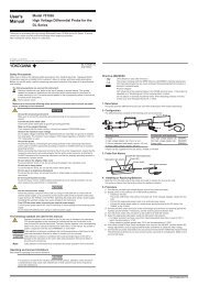
DIMENSIONS<br />
13 213<br />
(1/2) (8-3/8)<br />
132<br />
(5-1/4)<br />
21<br />
(7/8)<br />
Unit: mm(inch)<br />
18.5 350 27<br />
(3/4) (13-3/4) (1-1/8)