Double-Width Centrifugal Fan Performance Supplement - Greenheck
Double-Width Centrifugal Fan Performance Supplement - Greenheck
Double-Width Centrifugal Fan Performance Supplement - Greenheck

Create successful ePaper yourself
Turn your PDF publications into a flip-book with our unique Google optimized e-Paper software.
Turning<br />
Turning<br />
Vanes<br />
Vanes<br />
Effect of Installation on <strong>Performance</strong><br />
Ratings presented in the performance tables and curves of this<br />
catalog were derived from tests made in accordance with AMCA<br />
Standard 210 — “Laboratory Methods of Testing <strong>Fan</strong>s for Ratings.”<br />
The AMCA test procedure utilizes an open inlet and a straight<br />
outlet duct to assure maximum static regain.<br />
Any installation with One inlet or discharge configurations that deviate<br />
from this standard fan may result in reduced fan performance.<br />
Restricted or unstable wheel Oneflow<br />
at the fan inlet can cause pre-rotation<br />
of incoming air diameter or uneven fan loading of the fan wheel yielding large<br />
system losses and wheel increased sound levels. Free discharge or<br />
turbulent flow in the diameter discharge ductwork will also result in system<br />
effect losses.<br />
Static pressure losses due to inlet and discharge conditions can<br />
be expressed in terms of system effect factors. The static pressure<br />
for selection of the fans equals the system static pressure plus the<br />
system effect factor.<br />
Some common inlet and discharge conditions which affect fan<br />
performance are:<br />
Non-Ducted Inlet Clearance<br />
One<br />
One fan<br />
fan wheel<br />
wheel diameter<br />
diameter<br />
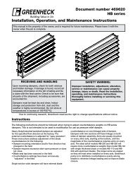
Installation of a fan with an open inlet too close to a wall or<br />
bulkhead will cause reduced fan performance. It is desirable to<br />
have one fan wheel diameter between the fan inlet and the wall.<br />
System effect Curve #2 depicts the pressure loss for one-half<br />
wheel diameter clearance.<br />
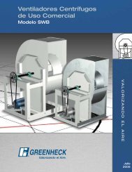
Free Discharge<br />
One fan<br />
wheel<br />
diameter One fan<br />
wheel<br />
diameter<br />
Turning<br />
Vanes Turning<br />
Free or abrupt discharge into a plenum results in a reduction in fan<br />
Vanes<br />
performance. The GOOD effect of static regain in discharge POOR is not realized.<br />
System effect Curve GOOD #1 depicts the pressure POOR loss for free or abrupt<br />
discharge.<br />
One fan<br />
wheel<br />
One fan<br />
diameter<br />
wheel<br />
diameter<br />
GOOD POOR<br />
GOOD POOR<br />
Static Pressure Loss<br />
7<br />
POOR<br />
GOOD<br />
Engineering Data<br />
POOR<br />
GOOD<br />
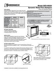
Duct turns located near the fan discharge should always be in the<br />
direction of the fan rotation.<br />
<strong>Fan</strong> performance is reduced when duct turns are made immediately<br />
off the fan discharge. To achieve cataloged fan performance there<br />
should be at least three equivalent duct diameters of straight<br />
ductwork between the POOR fan discharge and any duct turns. Curve #3<br />
shows the system POOR effect factor for two diameters of straight<br />
ductwork and Curve #1 for one diameter.<br />
Length of Straight Duct<br />
System Effect Length Factor of Straight Curves Duct<br />
Additional information on system effect factors can be found<br />
in AMCA Publication 201 — “<strong>Fan</strong>s and Systems” and ASHRAE<br />
Handbooks. System Effect Factor Curves<br />
1.2<br />
1.2<br />
1.0<br />
1.0<br />
0.8<br />
0.8<br />
0.6<br />
0.6<br />
0.4<br />
0.4<br />
0.2<br />
System GOODEffect<br />
Factor Curves<br />
GOOD<br />
0.2<br />
1.2<br />
0.0<br />
1.20.0<br />
0<br />
0<br />
System Effect Factor Curves<br />
System 5 10 Effect 15 Factor 20 Curves 25 30 35<br />
5 10 15 20 25 30 35<br />
Outlet Velocity (FPM x 100)<br />
40<br />
40<br />
45<br />
45<br />
1.0<br />
0.8<br />
0.6<br />
0.4<br />
0.2<br />
1.0<br />
0.8<br />
0.6<br />
0.4<br />
0.2<br />
0.0<br />
Outlet Velocity (FPM x 100)<br />
0.0 0 5 10 15 20 25 30 35 40 45<br />
0 5 10 15 20 25 30 35<br />
Outlet Velocity (FPM x 100)<br />
40 45<br />
Outlet Velocity (FPM x 100)<br />
Static Static Pressure Loss Loss<br />
Static Pressure Loss<br />
Rotation<br />
Rotation<br />
Rotation<br />
Rotation<br />
Rotation<br />
Rotation<br />
Rotation<br />
POOR<br />
Discharge Duct Turns<br />
Rotation<br />
Rotation<br />
Rotation<br />
POOR<br />
POOR<br />
Turning<br />
Turning<br />
Vanes<br />
Vanes<br />
POOR<br />
Length of Straight Duct<br />
Length of Straight Duct<br />
GOOD<br />
GOOD<br />
GOOD<br />
®<br />
Rotation<br />
Curve 1<br />
Curve 1Curve<br />
1<br />
GOOD<br />
Rotation<br />
Curve 1<br />
Curve 2<br />
Curve 2<br />
Curve 3<br />
Curve 2Curve<br />
2<br />
Curve 3<br />
Curve 3<br />
Curve 3