
You also want an ePaper? Increase the reach of your titles
YUMPU automatically turns print PDFs into web optimized ePapers that Google loves.
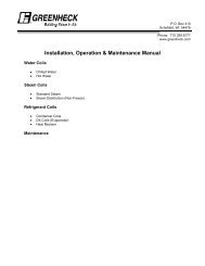
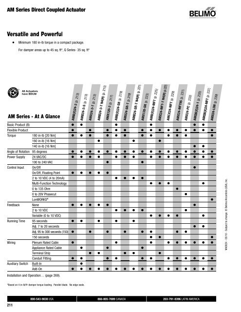
AM <strong>Series</strong> Direct Coupled ActuatorVersatile and Powerful●Minimum 180 in-lb torque in a compact package.For damper areas up to 45 sq. ft*, Q <strong>Series</strong>- 35 sq. ft*All Actuatorshave BDCMAM <strong>Series</strong> - At A Glance<strong>AMB</strong>(X)24-3 (p. 213)<strong>AMB</strong>24-3-S (p. 213)AMX24-3-T (p. 213)<strong>AMB</strong>24-3-T N4(H) (p. 215)AMX120-3 (p. 217)<strong>AMB</strong>(X)24-SR (p. 219)AMX24-SR-T (p. 219)<strong>AMB</strong>24-SR-T N4(H) (p. 221)AMX120-SR (p. 223)<strong>AMB</strong>(X)24-MFT (p. 225)AMX24-MFT-T N4(H) (p. 227)AMCX24-MFT (p. 229)AMX24-MFT95 (p. 231)AMX24-PC (p. 233)AMQB(X)24-1 (p. 235)AMQB(X)24-MFT (p. 237)AMX24-LON (p. 239)Basic Product (B) ● ● ● ● ● ●Flexible Product ● ● ● ● ● ● ● ● ● ● ● ● ● ●Torque 180 in-lb [20 Nm] ● ● ● ● ● ● ● ● ● ● ● ●160 in-lb [16 Nm] ● ● ●140 in-lb [16 Nm] ● ●Angle of Rotation 95 degrees ● ● ● ● ● ● ● ● ● ● ● ● ● ● ● ● ●Power Supply 24 VAC/DC ● ● ● ● ● ● ● ● ● ● ● ● ● ● ●100 to 240 VAC ● ●Control Input On/Off ●On/Off, Floating Point ● ● ● ● ●2 to 10 VDC (4 to 20mA) ● ● ● ●Multi-Function Technology ● ● ● ●0 to 135 Ohm ●0 to 20V Phasecut ●LonWORKS ®●Feedback None ● ● ● ● ● ●2 to 10 VDC ● ● ● ● ●Variable (0 to 10 VDC) ● ● ● ● ●Running Time 95 seconds ● ● ● ● ●Adj. 7 to 20 seconds ● ●Adj. 95 to 300 seconds (150) ● ● ● ● ● ● ● ●150 seconds ● ● ●Wiring Plenum Rated Cable ● ● ● ● ● ● ● ● ●Appliance Rated Cable ● ● ●Terminal Strip ● ● ● ● ●Conduit Fitting ● ● ● ● ● ● ● ● ● ● ● ●Auxiliary Switch Built-In ●Add-On ● ● ● ● ● ● ● ● ● ● ● ● ● ● ● ● ●M40024 - 05/10 - Subject to change. © Belimo Aircontrols (USA), Inc.Installation and Operation… (page 269).*Based on 4 in-lb/ft 2 damper torque loading. Parallel blade. No edge seals.211800-543-9038 USA 866-805-7089 CANADA 203-791-8396 LATIN AMERICA
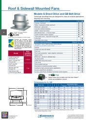
AM <strong>Series</strong> Direct Coupled ActuatorA CLOSER LOOK…●●Brushless DC Motor for Added Accuracy and Controllability.Cut Labor Costs with Simple Direct Coupling.● Self-Centers on 1/2",3/4", and 1.05"Jackshafts with Standard Clamp.●●●●●●●●Check Damper Position with Clear Position Indicator.Don’t Worry about Actuator Burn-Out; Belimo is Overload Proofthroughout Rotation.Enjoy Added Flexibility with Easy Mechanical Stopsto Adjust Angle of Rotation.Need to Change Control Direction?Do it easily with a Simple Switch.Easily Accessible Manual Override Button helpsyou Pre-Tension Damper Blades.Fully Adjustable Built-In Auxiliary Switch (<strong>AMB</strong>24-3-S).Auxiliary Switch and Feedback Potentiometer Add-Ons MountDirectly on Clamp, Includes Conduit Connector.Standard 3ft Plenum Rated Cable and Conduit Connector Providedon Basic Models.M40024 - 05/10 - Subject to change. © Belimo Aircontrols (USA), Inc.●Added Flexibility to Select Clamp, Electrical Connection, andRunning Time to fit your Specific Application with Belimo’s NewFlexible Line of Actuators.The Belimo Difference●●Customer Commitment.Extensive product range. Application assistance.Same-day shipments. Free technical support. Five year warranty.Low Installation and Life-Cycle Cost.Easy installation. Accuracy and repeatability.Low power consumption. No maintenance.●Long Service Life.Components tested before assembly. Every product tested before shipment.30+ years direct coupled actuator design.800-543-9038 USA 866-805-7089 CANADA 203-791-8396 LATIN AMERICA212
<strong>AMB</strong>(X)24-3(-S)(-T)On/Off, Floating Point, Non-Spring Return, 24 VAccessoriesK-SAReversible ClampZG-100Universal Mounting BracketZG-101Universal Mounting BracketZG-103Universal Mounting BracketZG-104Universal Mounting BracketZ-SMAAM/SM to AM Retrofit Mounting BracketZG-NMA Crank arm Adaptor KitAV8-25Universal Shaft ExtensionZG-JSA (-1, 2,3) Jackshaft Adaptors for Hollow JackshaftsZS-T Terminal Cover for NEMA 2ZS-100Weather Shield - SteelZS-150Weather Shield - PolycarbonateZS-260Explosion Proof HousingZS-300 (-1) (-5) NEMA 4X HousingTool-068 mm & 10 mm WrenchPS-100Actuator Power Supply SimulatorS1A, S2A Auxiliary Switch (es)P370Shaft Mount Auxiliary SwitchP…AFeedback PotentiometersNOTE: When using AM...24-3… actuators, only use accessories listed on this page.Typical SpecificationFloating point, on/off control damper actuators shall be electronic direct-coupled type,which require no crank arm and linkage and be capable of direct mounting to a shaftup to 1.05” diameter. Actuators shall have brushless DC motor technology and beprotected from overload at all angles of rotation. Actuators shall have reversing switchand manual override on the cover. If required, actuators shall be provided with oneadjustable SPDT auxiliary switch. Actuators with auxiliary switches must beconstructed to meet the requirements for double insulation so an electrical ground isnot required to meet agency listings. If required, actuators will be provided with ascrew terminal strip for electrical connections (AMX24-3-T). Run time shall beconstant and independent of torque. Actuators shall be cULus listed, have a 5-yearwarranty, and be manufactured under ISO 9001 International Quality ControlStandards. Actuators shall be as manufactured by Belimo.Wiring Diagrams1 Provide overload protection and disconnect as required.3 Actuators may also be powered by 24 VDC.For end position indication, interlock control, fan startup, etc.,<strong>AMB</strong>24-3-S incorporates one built-in auxiliary switches:1 x SPDT, 3A (0.5A) @250 VAC, UL Approved, adjustable 0 to 95.Meets cULus or UL and CSA Standard requirements without theneed of an electrical ground connection.WARNING Live Electrical Components!During installation, testing, servicing and troubleshooting of this product, it may benecessary to work with live electrical components. Have a qualifi ed licensed electrician or otherindividual who has been properly trained in handling live electrical components perform thesetasks. Failure to follow all electrical safety precautions when exposed to live electrical componentscould result in death or serious injury.On/Off controlW259_08M40024 - 05/10 - Subject to change. © Belimo Aircontrols (USA), Inc.Floating Point or On/Off controlW260_08W258_08Auxiliary Switch800-543-9038 USA 866-805-7089 CANADA 203-791-8396 LATIN AMERICA214
<strong>AMB</strong>24-3-T N4, <strong>AMB</strong>24-3-T N4HNEMA 4X, On/Off, Floating Point Control, Non-Spring Return, Direct Coupled, 24VTorque min. 160 in-lb for control of damper surfaces up to 40 sq ft.Technical Data<strong>AMB</strong>24-3-T N4, <strong>AMB</strong>24-3-T N4HPower supply24 VAC ± 20% 50/60 Hz24 VDC ± 10%Power consumption2.5 W (0.5 W) / heater 23 WTransformer sizing5.5 VA (Class 2 power source) / heater 20.5 VAElectrical connection screw terminal (for 26 to 14 GA wire [heater 15GA wire])1/2” conduit connectorOverload protectionelectronic throughout 0 to 95° rotationControlon/off, floating pointInput impedance600 ΩAngle of rotationmax. 95°, adjust. with mechanical stopTorque160 in-lb [16 Nm]Direction of rotation reversible with switchPosition indicationpointerManual overrideexternal push buttonRunning time95 secondsconstant independent of loadHumidity 5 to 95% RH non condensing (EN 60730-1)Ambient temperature -22°F to 122°F [-30°C to 50°C]Storage temperature -40°F to 176°F [-40°C to 80°C]HousingUL Type 4X, NEMA 4X, IP66/67Housing materialUL94-5VAAgency listings†ccULus acc. to UL 60730-1A/-2-14,CAN/CSA E60730-1, CSA C22.2 No. 24-93,CE acc. to 89/336/EECNoise level
AMX120-3On/Off, Floating Point, Non-Spring Return, 100 to 240 VACTorque min. 180 in-lb for control of damper surfaces up to 45 sq ft.Technical DataAMX120-3Power supply100 to 240 VAC, 50/60 Hz (nominal)85 to 265 VAC, 50/60 Hz (tolerance)Power consumption 3 W (0.6 W)Transformer sizing7 VA (Class 2 power source)Electrical connection 18 GA appliance rated cable1/2” conduit connectorprotected NEMA 2 (IP54)3 ft [1m] 10 ft [3m] 16 ft [5m]Overload protectionelectronic throughout 0 to 95° rotationControlon/off, floating pointInput impedance600 ΩAngle of rotationmax. 95°, adjust. with mechanical stopTorque180 in-lb [20 Nm]Direction of rotation reversible with switchPosition indicationreflective visual indicator (snap-on)Manual overrideexternal push buttonRunning time300 seconds 150 seconds 95 secondsconstant independent of loadHumidity 5 to 95% RH non condensing (EN 60730-1)Ambient temperature -22°F to 122°F [-30°C to 50°C]Storage temperature -40°F to 176°F [-40°C to 80°C]HousingNEMA 2/IP54Housing material NEMA 2, IP54, UL enclosure type 2Agency listings†cULus acc. to UL 60730-1A/-2-14,CAN/CSA E60730-1:02,CE acc. to 2004/108/EEC and 2006/95/ECNoise level
AMX120-3On/Off, Floating Point, Non-Spring Return, 100 to 240 VACAccessoriesK-SAReversible ClampZG-100Universal Mounting BracketZG-101Universal Mounting BracketZG-103Universal Mounting BracketZG-104Universal Mounting BracketZ-SMAAM/SM to AM Retrofit Mounting BracketZG-NMA Crank arm Adaptor KitAV8-25Universal Shaft ExtensionZG-JSA (-1, 2,3) Jackshaft Adaptors for Hollow JackshaftsZS-100Weather Shield - SteelZS-150Weather Shield - PolycarbonateZS-260Explosion Proof HousingZS-300 (-1) (-5) NEMA 4X HousingTool-068 mm & 10 mm WrenchPS-100Actuator Power Supply SimulatorS1A, S2A Auxiliary Switch (es)P370Shaft Mount Auxiliary SwitchP…AFeedback PotentiometersNOTE: When using AMX120-3 actuators, only use accessories listed on this page.Wiring Diagrams1 Provide overload protection and disconnect as required.2 CAUTION Equipment Damage!Actuators may be connected in parallel.Power consumption and input impedance must be observed.Meets cULus or UL and CSA Standard requirements without theneed of an electrical ground connection.WARNING Live Electrical Components!During installation, testing, servicing and troubleshooting of this product, it may benecessary to work with live electrical components. Have a qualifi ed licensed electrician or otherindividual who has been properly trained in handling live electrical components perform thesetasks. Failure to follow all electrical safety precautions when exposed to live electrical componentscould result in death or serious injury.Typical SpecificationFloating point, on/off control damper actuators shall be electronic direct-coupled type,which require no crank arm and linkage and be capable of direct mounting to a shaftup to 1.05” diameter. Actuators shall have brushless DC motor technology and beprotected from overload at all angles of rotation. Actuators shall have reversing switchand manual override on the cover. Run time shall be constant and independent oftorque. Actuators shall be cULus listed, have a 5-year warranty, and be manufacturedunder ISO 9001 International Quality Control Standards. Actuators shall be asmanufactured by Belimo.On/Off controlM40024 - 05/10 - Subject to change. © Belimo Aircontrols (USA), Inc.Floating Point or On/Off control800-543-9038 USA 866-805-7089 CANADA 203-791-8396 LATIN AMERICA218
<strong>AMB</strong>(X)24-SR(-T)Proportional, Non-Spring Return, 24 V, for 2 to 10 VDC or 4 to 20 mATorque min. 180 in-lb for control of damper surfaces up to 45 sq ft.Technical Data<strong>AMB</strong>(X)24-SR(-T)Power supply24 VAC ± 20% 50/60 Hz24 VDC ± 10%Power consumption 2.5 W (0.4 W)Transformer sizing5 VA (Class 2 power source)Electrical connection 18 GA plenum rated cable1/2” conduit connectorprotected NEMA 2 (IP54)3 ft [1m] 10 ft [3m] 16 ft [5m]Overload protectionelectronic throughout 0 to 95° rotationOperating range Y2 to 10 VDC, 4 to 20 mAInput impedance100 kΩ (0.1 mA), 500 ΩFeedback output U2 to 10 VDC (max 0.5 mA)Angle of rotationmax. 95°, adjust. with mechanical stopTorque180 in-lb [20 Nm]Direction of rotation reversible with switchactuator will move:=CCW with decreasing control signal (10 to 2V)=CW with decreasing control signal (10 to 2V)Position indicationreflective visual indicator (snap-on)Manual overrideexternal push buttonRunning time300 seconds 150 seconds 95 secondsconstant independent of loadHumidity 5 to 95% RH non condensing (EN 60730-1)Ambient temperature -22°F to 122°F [-30°C to 50°C]Storage temperature -40°F to 176°F [-40°C to 80°C]Housing NEMA 2, IP54, UL enclosure type 2Housing materialUL94-5VAAgency listings†cULus acc. to UL 60730-1A/-2-14,CAN/CSA E60730-1:02,CE acc. to 2004/108/EEC and 2006/95/ECNoise level
<strong>AMB</strong>(X)24-SR(-T)Proportional, Non-Spring Return, 24 V, for 2 to 10 VDC or 4 to 20 mAAccessoriesK-SAReversible ClampZG-100Universal Mounting BracketZG-101Universal Mounting BracketZG-103Universal Mounting BracketZG-104Universal Mounting BracketZ-SMAAM/SM to AM Retrofit Mounting BracketZG-NMA Crank arm Adaptor KitAV8-25Universal Shaft ExtensionZG-JSA (-1, 2, 3) Jackshaft Adaptors for Hollow JackshaftsZS-T Terminal Cover NEMA 2ZS-100Weather Shield - SteelZS-150Weather Shield - PolycarbonateZS-260Explosion Proof HousingZS-300 (-1) (-5) NEMA 4X HousingTool-068 mm & 10 mm WrenchS1A, S2A Auxiliary Switch (es)P370Shaft Mount Auxiliary SwitchP…AFeedback PotentiometersSGA24Min positioners in NEMA 4 housingSGF24Min positioners for flush panel mountingPTA-250 Pulse Width Modulation InterfaceIRM-100 Input Rescaling ModuleADS-100 Analog to Digital SwitchZG-R01Resistor for 4 to 20 mA ConversionNSV24 US Battery Back-Up ModuleZG-X40TransformerNOTE: When using <strong>AMB</strong>(X)24-SR… actuators, only use accessories listed on this page.Wiring Diagrams1 Provide overload protection and disconnect as required.2 CAUTION Equipment Damage!Actuators may be connected in parallel.Power consumption and input impedance must be observed.3 Actuators may also be powered by 24 VDC.5 Only connect common to neg. (–) leg of control circuits.The ZG-R01 500 Ω resistor converts the 4 to 20 mA control signal to2 to 10 VDC, up to 2 actuators may be connected in parallel.WARNING Live Electrical Components!During installation, testing, servicing and troubleshooting of this product, it may benecessary to work with live electrical components. Have a qualifi ed licensed electrician or otherindividual who has been properly trained in handling live electrical components perform thesetasks. Failure to follow all electrical safety precautions when exposed to live electrical componentscould result in death or serious injury.W257_08Typical SpecificationM40024 - 05/10 - Subject to change. © Belimo Aircontrols (USA), Inc.Proportional control damper actuators shall be electronic direct-coupled type, whichrequire no crank arm and linkage and be capable of direct mounting to a shaft up to1.05” diameter. Actuators must provide proportional damper control in response to a 2to 10 VDC or, with the addition of a 500 Ω resistor, a 4 to 20 mA control input from anelectronic controller or positioner. Actuators shall have brushless DC motor technologyand be protected from overload at all angles of rotation. Actuators shall have reversingswitch and manual override on the cover. If required, actuator will be provided withscrew terminal strip for electrical connections (AMX24-SR-T). Run time shall beconstant and independent of torque. A 2 to 10 VDC feedback signal shall be providedfor position indication. Actuators shall be cULus listed, have a 5-year warranty, and bemanufactured under ISO 9001 International Quality Control Standards. Actuators shallbe as manufactured by Belimo.2 to 10 VDC control4 to 20 mA controlW257_08800-543-9038 USA 866-805-7089 CANADA 203-791-8396 LATIN AMERICA220
<strong>AMB</strong>24-SR-T N4, <strong>AMB</strong>24-SR-T N4HNEMA 4X, Proportional Control, Non-Spring Return, Direct Coupled, 24V, for 2 to 10 VDC and 4 to 20 mATorque min. 160 in-lb for control of damper surfaces up to 40 sq ft.Technical Data<strong>AMB</strong>24-SR-T N4, <strong>AMB</strong>24-SR-T N4HPower supply24 VAC ± 20% 50/60 Hz24 VDC ± 10%Power consumption2.5 W (0.4 W) / heater 23 WTransformer sizing5 VA (Class 2 power source) / heater 20 VAElectrical connection screw terminal (for 26 to 14 GA wire [heater 15GA wire])1/2” conduit connectorOverload protectionelectronic throughout 0 to 95° rotationOperating range Y2 to 10 VDC, 4 to 20 mAInput impedance100 kΩ (0.1 mA), 500 ΩFeedback output U2 to 10 VDC (max 0.5 mA)Angle of rotationmax. 95°, adjust. with mechanical stopTorque160 in-lb [16 Nm]Direction of rotation reversible with switchPosition indicationpointerManual overrideexternal push buttonRunning time95 seconds, constant independent of loadHumidity 5 to 95% RH non condensing (EN 60730-1)Ambient temperature -22°F to 122°F [-30°C to 50°C]Storage temperature -40°F to 176°F [-40°C to 80°C]HousingUL type 4X, NEMA 4X, IP66/67Housing materialUL94-5VAAgency listings†cULus acc. to UL 60730-1A/-2-14,CAN/CSA E60730-1, CSA C22.2 No. 24-93,CE acc. to 89/336/EECNoise level
AMX24-SR-T N4, AMX24-SR-T N4HNEMA 4X, Proportional Control, Non-Spring Return, Direct Coupled, 24V, for 2 to 10 VDC and 4 to 20 mAAccessoriesS1A, S2AP…ASGA24SGF24PTA-250IRM-100ADS-100ZG-R01NSV24 USZG-X40Auxiliary Switch (es)Feedback PotentiometersMin positioners for surface mountingMin positioners for flush panel mountingPulse Width Modulation InterfaceInput Rescaling ModuleAnalog to Digital SwitchResistor for 4 to 20 mA ConversionBattery Back-Up ModuleTransformerWiring Diagram1 Provide overload protection and disconnect as required.2 CAUTION Equipment damage!Actuators may be connected in parallel.Power consumption and input impedance must be observed.3 Actuators may also be powered by 24 VDC.5 Only connect common to neg. (–) leg of control circuits.Typical SpecificationProportional control damper actuators shall be electronic direct-coupled type, whichrequire no crank arm and linkage and be capable of direct mounting to a shaft up to¾” diameter. Actuators must provide proportional damper control in response to a 2 to10 VDC or, with the addition of a 500 Ω resistor, a 4 to 20 mA control input from anelectronic controller or positioner. Actuators shall have brushless DC motor technologyand be protected from overload at all angles of rotation. Actuators shall have reversingswitch and manual override on the cover. Run time shall be constant and independentof torque. A 2 to 10 VDC feedback signal shall be provided for position indication.Actuators shall be cULus listed, have a 5-year warranty, and be manufactured underISO 9001 International Quality Control Standards. Actuators shall be as manufacturedby Belimo.Wiring DiagramThe ZG-R01 500 Ω resistor converts the 4 to 20 mA control signal to2 to 10 VDC, up to 2 actuators may be connected in parallel.WARNING Live Electrical Components!During installation, testing, servicing and troubleshooting of this product, it may benecessary to work with live electrical components. Have a qualified licensed electricianor other individual who has been properly trained in handling live electricalcomponents perform these tasks. Failure to follow all electrical safety precautionswhen exposed to live electrical components could result in death or serious injury.ith actuator types ..-SR or MFTN L1 2 3 5 1 2TNLLegend:M = actuatorT (°C) = ThermostatH = HeatingT(°C)H<strong>AMB</strong>24-SR-T N4M40024 - 05/10 - Subject to change. © Belimo Aircontrols (USA), Inc.MHeater wiring12NoteThe following points must be taken into accountwith independent, external wiring:• All contact between the cables or wires thatare introduced and the heating element is to beavoided.• Where necessary, use cables with sufficientnumbers of wires, e.g. so that the heating and theactuator can be supplied separately with voltage.2 to 10 VDC control4 to 20 mA control<strong>AMB</strong>24-SR-T N4800-543-9038 USA 866-805-7089 CANADA 203-791-8396 LATIN AMERICA222
AMX120-SRProportional, Non-Spring Return, 100 to 240 VAC, for 2 to 10 VDC or 4 to 20 mATorque min. 180 in-lb for control of damper surfaces up to 45 sq ft.Technical DataAMX120-SRPower supply100 to 240 VAC, 50/60 Hz (nominal)85 to 265 VAC, 50/60 Hz (tolerance)Power consumption 4 W (1 W)Transformer sizing7.5 VA (Class 2 power source)Electrical connection 18 GA appliance rated cable1/2” conduit connectorprotected NEMA 2 (IP54)3 ft [1m] 10 ft [3m] 16 ft [5m]Overload protectionelectronic throughout 0 to 95° rotationOperating range Y2 to 10 VDC, 4 to 20 mAInput impedance100 kΩ (0.1 mA), 500 ΩFeedback output U2 to 10 VDC (max 0.5 mA)Angle of rotationmax. 95°, adjust. with mechanical stopTorque180 in-lb [20 Nm]Direction of rotation reversible with switchactuator will move:=CCW with decreasing control signal (10 to 2V)=CW with decreasing control signal (10 to 2V)Position indicationreflective visual indicator (snap-on)Manual overrideexternal push buttonRunning time300 seconds 150 seconds 95 secondsconstant independent of loadHumidity 5 to 95% RH non condensing (EN 60730-1)Ambient temperature -22°F to 122°F [-30°C to 50°C]Storage temperature -40°F to 176°F [-40°C to 80°C]Housing NEMA 2, IP54, UL enclosure type 2Housing materialUL94-5VAAgency listings†cULus acc. to UL 60730-1A/-2-14,CAN/CSA E60730-1:02,CE acc. to 2004/108/EEC and 2006/95/ECNoise level
AMX120-SRProportional, Non-Spring Return, 100 to 240 VAC, for 2 to 10 VDC or 4 to 20 mAAccessoriesK-SAReversible ClampZG-100Universal Mounting BracketZG-101Universal Mounting BracketZG-103Universal Mounting BracketZG-104Universal Mounting BracketZ-SMAAM/SM to AM Retrofit Mounting BracketZG-NMA Crank arm Adaptor KitAV8-25Universal Shaft ExtensionZG-JSA (-1, 2, 3) Jackshaft Adaptors for Hollow JackshaftsZS-100Weather Shield - SteelZS-150Weather Shield - PolycarbonateZS-260Explosion Proof HousingZS-300 (-1) (-5) NEMA 4X HousingTool-068 mm & 10 mm WrenchS1A, S2A Auxiliary Switch (es)P370Shaft Mount Auxiliary SwitchP…AFeedback PotentiometersSGA24Min positioners in NEMA 4 housingSGF24Min positioners for flush panel mountingPTA-250 Pulse Width Modulation InterfaceIRM-100 Input Rescaling ModuleADS-100 Analog to Digital SwitchZG-R01Resistor for 4 to 20 mA ConversionNSV24 US Battery Back-Up ModuleZG-X40TransformerNOTE: When using AMX120-SR actuators, only use accessories listed on this page.Wiring Diagram1 Provide overload protection and disconnect as required.2 CAUTION Equipment Damage!Actuators may be connected in parallel.Power consumption and input impedance must be observed.5 Only connect common to neg. (–) leg of control circuits.Meets cULus or UL and CSA Standard requirements without theneed of an electrical ground connection.The ZG-R01 500 Ω resistor converts the 4 to 20 mA control signal to2 to 10 VDC, up to 2 actuators may be connected in parallel.WARNING Live Electrical Components!During installation, testing, servicing and troubleshooting of this product, it may benecessary to work with live electrical components. Have a qualifi ed licensed electrician or otherindividual who has been properly trained in handling live electrical components perform thesetasks. Failure to follow all electrical safety precautions when exposed to live electrical componentscould result in death or serious injury.W374_08M40024 - 05/10 - Subject to change. © Belimo Aircontrols (USA), Inc.Typical SpecificationProportional control damper actuators shall be electronic direct-coupled type, whichrequire no crank arm and linkage and be capable of direct mounting to a shaft up to1.05” diameter. Actuators must provide proportional damper control in response to a 2to 10 VDC or, with the addition of a 500 Ω resistor, a 4 to 20 mA control input from anelectronic controller or positioner. Actuators shall have brushless DC motor technologyand be protected from overload at all angles of rotation. Actuators shall have reversingswitch and manual override on the cover. Run time shall be constant and independentof torque. A 2 to 10 VDC feedback signal shall be provided for position indication.Actuators shall be cULus listed, have a 5-year warranty, and be manufactured underISO 9001 International Quality Control Standards. Actuators shall be as manufacturedby Belimo.2 to 10 VDC or 4 to 20 mA control800-543-9038 USA 866-805-7089 CANADA 203-791-8396 LATIN AMERICA224
<strong>AMB</strong>(X)24-MFTProportional, Non-Spring Return, 24 V, Multi-Function Technology ®Torque min. 180 in-lb for control of damper surfaces up to 45 sq ft.Technical Data<strong>AMB</strong>(X)24-MFTPower supply24 VAC ± 20% 50/60 Hz24 VDC ± 10%Power consumption 3.5 W (1.3 W)Transformer sizing6 VA (Class 2 power source)Electrical connection 18 GA plenum rated cable1/2” conduit connectorprotected NEMA 2 (IP54)3 ft [1m] 10 ft [3m] 16 ft [5m]Overload protectionelectronic throughout 0 to 95° rotationOperating range Y2 to 10 VDC, 4 to 20 mA (default)variable (VDC, PWM, floating point, on/off)Input impedance100 kΩ (0.1 mA), 500 Ω1500 W (PWM, floating point, on/off)Feedback output U2 to 10 VDC, 0.5 mA maxVDC variableAngle of rotationmax. 95°, adjustable with mechanical stopelectronically variableTorque180 in-lb [20 Nm]Direction of rotation reversible with switchPosition indicationreflective visual indicator (snap-on)Manual overrideexternal push buttonRunning time150 seconds (default)variable (90 to 350 seconds)Humidity 5 to 95% RH non condensing (EN 60730-1)Ambient temperature -22°F to 122°F [-30°C to 50°C]Storage temperature -40°F to 176°F [-40°C to 80°C]Housing NEMA 2, IP54, UL enclosure type 2Housing materialUL94-5VAAgency listings†cULus acc. to UL 60730-1A/-2-14,CAN/CSA E60730-1:02,CE acc. to 2004/108/EEC and 2006/95/ECNoise level
<strong>AMB</strong>(X)24-MFTProportional, Non-Spring Return, 24 V, Multi-Function Technology ®AccessoriesK-SAReversible ClampZG-100Universal Mounting BracketZG-101Universal Mounting BracketZG-103Universal Mounting BracketZG-104Universal Mounting BracketZ-SMAAM/SM to AM Retrofit Mounting BracketZG-AMACrank arm Adaptor KitAV8-25Universal Shaft ExtensionZG-JSA (-1, 2, 3) Jackshaft Adaptors for Hollow JackshaftsZS-100Weather Shield - SteelZS-150Weather Shield - PolycarbonateZS-260Explosion Proof HousingZS-300 (-1) (-5) NEMA 4X HousingTool-068 mm & 10 mm WrenchS1A, S2A Auxiliary Switch (es)P370Shaft Mount Auxiliary SwitchP…AFeedback PotentiometersSGA24Min positioners in NEMA 4 housingSGF24Min positioners for flush panel mountingADS-100 Analog to Digital SwitchZG-R01Resistor for 4 to 20 mA ConversionNSV24 US Battery Back-Up ModuleZG-X40TransformerNOTE: When using <strong>AMB</strong>(X)24-MFT… actuators, only use accessories listed on this page.WARNING Live Electrical Components!During installation, testing, servicing and troubleshooting of this product, it may benecessary to work with live electrical components. Have a qualifi ed licensed electrician or otherindividual who has been properly trained in handling live electrical components perform thesetasks. Failure to follow all electrical safety precautions when exposed to live electrical componentscould result in death or serious injury.VDC/4-20 mAW399_08W399_08Typical SpecificationM40024 - 05/10 - Subject to change. © Belimo Aircontrols (USA), Inc.Proportional control damper actuators shall be electronic direct-coupled type, whichrequire no crank arm and linkage and be capable of direct mounting to a shaft up to1.05” diameter. Actuators must provide proportional damper control in response to a 2to 10 VDC or, with the addition of a 500 Ω resistor, a 4 to 20 mA control input from anelectronic controller or positioner. Actuators shall have brushless DC motor technologyand be protected from overload at all angles of rotation. Actuators shall have reversingswitch and manual override on the cover. Run time shall be constant and independentof torque. Actuators shall be cULus listed, have a 5-year warranty, and bemanufactured under ISO 9001 International Quality Control Standards. Actuators shallbe as manufactured by Belimo.Wiring Diagrams1 Provide overload protection and disconnect as required.2CAUTION Equipment Damage!Actuators may be connected in parallel if not mechanically mounted to the sameshaft. Power consumption and input impedance must be observed.3 Actuators may also be powered by 24 VDC.4589Position feedback cannot be used with Triac sink controller.The actuator internal common reference is not compatible.Control signal may be pulsed from either the Hot (source)or the Common (sink) 24 VAC line.Contact closures A & B also can be triacs.A & B should both be closed for triac source and open for triac sink.For triac sink the common connection from the actuatormust be connected to the hot connection of the controller.PWMOn/Off Off controlW399_08W399_08The ZG-R01 500 Ω resistor may be used.Floating Point control800-543-9038 USA 866-805-7089 CANADA 203-791-8396 LATIN AMERICA226
AMX24-MFT-T N4, AMX24-MFT-T N4HNEMA 4X, Proportional Control, Non-Spring Return, Direct Coupled, 24V, Multi-Function Technology ®Torque min. 160 in-lb for control of damper surfaces up to 40 sq ft.Technical DataAMX24-MFT-T N4, AMX24-MFT-T N4HPower supply24 VAC ± 20% 50/60 Hz24 VDC ± 10%Power consumption3.5 W (1.25 W) / heater 24 WTransformer sizing6 VA (Class 2 power source) / heater 21 VAElectrical connection screw terminal (for 26 to 14 GA wire [heater 15GA wire])1/2” conduit connectorOverload protectionelectronic throughout 0 to 95° rotationOperating range Y2 to 10 VDC, 4 to 20 mA (default)variable (VDC, PWM, floating point, on/off)Input impedance100 kΩ (0.1 mA), 500 Ω1500 Ω (PWM, floating point, on/off)Feedback output U2 to 10 VDC, 0.5 mA maxVDC variableAngle of rotationmax. 95°, adjustable with mechanical stopelectronically variableTorque160 in-lb [16 Nm]Direction of rotation reversible with switchPosition indicationpointerManual overrideexternal push buttonRunning time150 seconds (default)variable (90 to 300 secondss)Humidity 5 to 95% RH non condensing (EN 60730-1)Ambient temperature -22°F to 122°F [-30°C to 50°C]Storage temperature -40°F to 176°F [-40°C to 80°C]HousingUL type 4X, NEMA 4X, IP66/67Housing materialUL94-5VAAgency listings†cULus acc. to UL 60730-1A/-2-14,CAN/CSA E60730-1, CSA C22.2 No. 24-93,CE acc. to 89/336/EECNoise level
AMX24-MFT-T N4, AMX24-MFT-T N4HNEMA 4X, Proportional Control, Non-Spring Return, Direct Coupled, 24V, Multi-Function Technology ®AccessoriesZS-100S1A, S2AP…ASGA24SGF24ADS-100ZG-R01NSV24 USZG-X40Weather Shield - SteelAuxiliary Switch (es)Feedback PotentiometersMin positioners for surface mountingMin positioners for flush panel mountingAnalog to Digital SwitchResistor for 4 to 20 mA ConversionBattery Back-Up ModuleTransformerW399_08Typical SpecificationProportional control damper actuators shall be electronic direct-coupled type, whichrequire no crank arm and linkage and be capable of direct mounting to a shaft up to¾” diameter. Actuators must provide proportional damper control in response to a 2 to10 VDC or, with the addition of a 500 Ω resistor, a 4 to 20 mA control input from anelectronic controller or positioner. Actuators shall have brushless DC motor technologyand be protected from overload at all angles of rotation. Actuators shall have reversingswitch and manual override on the cover. Run time shall be constant and independentof torque. Actuators shall be cULus listed, have a 5-year warranty, and bemanufactured under ISO 9001 International Quality Control Standards. Actuators shallbe as manufactured by Belimo.Wiring DiagramsPWMW399_08On/Off control1 Provide overload protection and disconnect as required.2CAUTION Equipment damage!Actuators may be connected in parallel if not mechanically mounted to thesame shaft. Power consumption and input impedance must be observed.W399_083 Actuators may also be powered by 24 VDC.M40024 - 05/10 - Subject to change. © Belimo Aircontrols (USA), Inc.4589Position feedback cannot be used with Triac sink controller.The actuator internal common reference is not compatible.Control signal may be pulsed from either the Hot (source)or the Common (sink) 24 VAC line.Contact closures A & B also can be triacs.A & B should both be closed for triac source and open for triac sink.For triac sink the common connection from the actuatormust be connected to the hot connection of the controller.The ZG-R01 500 Ω resistor may be used.WARNING Live Electrical Components!During installation, testing, servicing and troubleshooting of this product,it may be necessary to work with live electrical components. Have a qualifi edlicensed electrician or other individual who has been properly trained in handlinglive electrical components perform these tasks. Failure to follow all electrical safetyprecautions when exposed to live electrical components could result in death orserious injury.W399_08Floating Point controlith actuator types ..-SR or MFTN L1 2 3 5 1 2MTHeater wiringNL12T(°C)HLegend:M = actuatorT (°C) = ThermostatH = HeatingNoteThe following points must be taken into accountwith independent, external wiring:• All contact between the cables or wires thatare introduced and the heating element is to beavoided.• Where necessary, use cables with sufficientnumbers of wires, e.g. so that the heating and theactuator can be supplied separately with voltage.VDC/4-20 mA800-543-9038 USA 866-805-7089 CANADA 203-791-8396 LATIN AMERICA228
AMCX24-MFTProportional, Non-Spring Return, 24 V, Multi-Function Technology ®Torque min. 180 in-lb for control of damper surfaces up to 45 sq ft.Technical DataAMCX24-MFTPower supply24 VAC ± 20% 50/60 Hz24 VDC ± 10%Power consumption 4 W (1.25 W)Transformer sizing6 VA (Class 2 power source)Electrical connection 18 GA plenum rated cable1/2” conduit connectorprotected NEMA 2 (IP54)3 ft [1m] 10 ft [3m] 16 ft [5m]Overload protectionelectronic throughout 0 to 95° rotationOperating range Y2 to 10 VDC, 4 to 20 mA (default)variable (VDC, PWM, floating point, on/off)Input impedance100 kΩ (0.1 mA), 500 Ω1500 W (PWM, floating point, on/off)Feedback output U2 to 10 VDC, 0.5 mA maxVDC variableAngle of rotationmax. 95°, adjustable with mechanical stopelectronically variableTorque180 in-lb [20 Nm]Direction of rotation reversible with switchPosition indicationreflective visual indicator (snap-on)Manual overrideexternal push buttonRunning time35 seconds (default)variable (35 to 120 seconds)Humidity 5 to 95% RH non condensing (EN 60730-1)Ambient temperature -22°F to 122°F [-30°C to 50°C]Storage temperature -40°F to 176°F [-40°C to 80°C]Housing NEMA 2, IP54, UL enclosure type 2Housing materialUL94-5VAAgency listings†cULus acc. to UL 60730-1A/-2-14,CAN/CSA E60730-1:02,CE acc. to 2004/108/EEC and 2006/95/ECNoise level
AMCX24-MFTProportional, Non-Spring Return, 24 V, Multi-Function Technology ®AccessoriesK-SAReversible ClampZG-100Universal Mounting BracketZG-101Universal Mounting BracketZG-103Universal Mounting BracketZG-104Universal Mounting BracketZ-SMAAM/SM to AM Retrofit Mounting BracketZG-AMACrank arm Adaptor KitAV8-25Universal Shaft ExtensionZG-JSA (-1, 2, 3) Jackshaft Adaptors for Hollow JackshaftsZS-100Weather Shield - SteelZS-150Weather Shield - PolycarbonateZS-260Explosion Proof HousingZS-300 (-1) (-5) NEMA 4X HousingTool-068 mm & 10 mm WrenchS1A, S2A Auxiliary Switch(es)P370Shaft Mount Auxiliary SwitchP…AFeedback PotentiometersSGA24Min positioners in NEMA 4 housingSGF24Min positioners for flush panel mountingADS-100 Analog to Digital SwitchZG-R01Resistor for 4 to 20 mA ConversionNSV24US Battery Back-Up ModuleZG-X40TransformerNote: When using AMCX24-MFT… actuators, only use accessories listed on this page.WARNING Live Electrical Components!During installation, testing, servicing and troubleshooting of this product, it may benecessary to work with live electrical components. Have a qualifi ed licensed electrician or otherindividual who has been properly trained in handling live electrical components perform thesetasks. Failure to follow all electrical safety precautions when exposed to live electrical componentscould result in death or serious injury.VDC/4-20 mAW399_08W399_08Typical SpecificationM40024 - 05/10 - Subject to change. © Belimo Aircontrols (USA), Inc.Proportional control damper actuators shall be electronic direct coupled type, whichrequire no crank arm and linkage and be capable of direct mounting to a shaft upto 1.05” diameter. Actuators must provide proportional damper control in responseto a 2 to 10 VDC or, with the addition of a 500 Ω resistor, a 4 to 20 mA control inputfrom an electronic controller or positioner. Actuators shall have brushless DC motortechnology and be protected from overload at all angles of rotation. Actuators shallhave reversing switch and manual override on the cover. Run time shall be constantand independent of torque. Actuators shall be cULus listed, have a 5-year warranty,and be manufactured under ISO 9001 International Quality Control Standards. Actuatorsshall be as manufactured by Belimo.Wiring Diagrams1 Provide overload protection and disconnect as required.2CAUTION Equipment Damage!A ctuators may be connected in parallel if not mechanically mounted to the sameshaft. Power consumption and input impedance must be observed.3 Actuators may also be powered by 24 VDC.4589Position feedback cannot be used with Triac sink controller.The actuator internal common reference is not compatible.Control signal may be pulsed from either the Hot (source)or the Common (sink) 24 VAC line.Contact closures A & B also can be triacs.A & B should both be closed for triac source and open for triac sink.For triac sink the common connection from the actuatormust be connected to the hot connection of the controller.PWMOn/Off Off controlW399_08W399_08The ZG-R01 500 Ω resistor may be used.Floating Point control800-543-9038 USA 866-805-7089 CANADA 203-791-8396 LATIN AMERICA230
AMX24-MFT95Proportional, Non-Spring Return, 24 V, 0 to 135 Ω InputTorque min. 180 in-lb for control of damper surfaces up to 45 sq ft.Technical DataAMX24-MFT95Power supply24 VAC ± 20% 50/60 Hz24 VDC ± 10%Power consumption 3.5 W (1.3 W)Transformer sizing6 VA (Class 2 power source)Electrical connection 18 GA plenum rated cable1/2” conduit connectorprotected NEMA 2 (IP54)3 ft [1m] 10 ft [3m] 16 ft [5m]Overload protectionelectronic throughout 0 to 95° rotationOperating range WRB 135 Ω Honeywell Electronic <strong>Series</strong> 90,0 to 135 Ω inputFeedback output U2 to 10 VDC, 0.5 mA maxAngle of rotationmax. 95°, adjustable with mechanical stopelectronically variableTorque180 in-lb [20 Nm]Direction of rotation reversible with switchPosition indicationreflective visual indicator (snap-on)Manual overrideexternal push buttonRunning time150 seconds (default)variable (90 to 350 seconds)Humidity 5 to 95% RH non condensing (EN 60730-1)Ambient temperature -22°F to 122°F [-30°C to 50°C]Storage temperature -40°F to 176°F [-40°C to 80°C]Housing NEMA 2, IP54, UL enclosure type 2Housing materialUL94-5VAAgency listings†cULus acc. to UL 60730-1A/-2-14,CAN/CSA E60730-1:02,CE acc. to 2004/108/EEC and 2006/95/ECNoise level
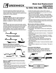
AMX24-MFT95Proportional, Non-Spring Return, 24 V, 0 to 135 Ω InputM40024 - 05/10 - Subject to change. © Belimo Aircontrols (USA), Inc.AccessoriesK-SAReversible ClampZG-100Universal Mounting BracketZG-101Universal Mounting BracketZG-103Universal Mounting BracketZG-104Universal Mounting BracketZ-SMAAM/SM to AM Retrofit Mounting BracketZG-AMACrank arm Adaptor KitAV8-25Universal Shaft ExtensionZG-JSA (-1, 2, 3) Jackshaft Adaptors for Hollow JackshaftsZS-100Weather Shield - SteelZS-150Weather Shield - PolycarbonateZS-260Explosion Proof HousingZS-300 (-1) (-5) NEMA 4X HousingTool-068 mm & 10 mm WrenchS1A, S2A Auxiliary Switch (es)P370Shaft Mount Auxiliary SwitchP…AFeedback PotentiometersNSV24 US Battery Back-Up ModuleZG-X40TransformerNOTE: When using AMX24-MFT95… actuators, only use accessories listed on this page.Typical SpecificationProportional control damper actuators shall be electronic direct-coupled type, whichrequire no crank arm and linkage and be capable of direct mounting to a shaft up to1.05” diameter. Actuators must provide proportional damper control in response to0 to 135 Ω control input from an electronic controller or positioner. Actuators shallhave brushless DC motor technology and be protected from overload at all angles ofrotation. Actuators shall have reversing switch and manual override on the cover. Runtime shall be constant and independent of torque. Actuators shall be cULus listed,have a 5-year warranty, and be manufactured under ISO 9001 International QualityControl Standards. Actuators shall be as manufactured by Belimo.Wire Colors1 = Black2 = RedOverride21LineVolts21LineVoltsLineVolts223 = White4 = Pink24 VAC Transformer135 ΩAB24 VAC TransformerWRBControllerAB5 = Gray6 = Orange5Blk (1) CommonRed (2) + Hot23Pnk (4) W 24Wht (3) RGry (5) BOrg (6) ‘U5’ Output 2 to 10 VDC-MFT95Blk (1) CommonRed (2) + Hot23Pnk (4) W 24Wht (3) RGry (5) BOrg (6) ‘U5’ Output 2 to 10 VDC-MFT95Wnew60408_6Wiring Diagrams5Actuators with plenum rated cable do not have numbers on wires; usecolor codes instead. Actuators with appliance cables are numbered.21 Provide overload protection and disconnect as required.22 Actuators and controller must have separate transformers.23 Consult controller instruction data for more detailed information.Resistor value depends on the type of controller and the number of24 actuators. No resistor is used for one actuator. Honeywell ® resistor kitsmay also be used.25 To reverse control rotation, use the reversing switch.LineVolts<strong>Series</strong> 90ControllerB2421ShuntingResistorB21LineVolts2224 VAC TransformerRWRWR22B23WH205 ChangeoverController OccupiedContactTo otheractuatorsS963AMinimum PositionPotentiometerWiring multiple actuators to a <strong>Series</strong> 90 controllerusing a minimum position potentiometer.Low Limit ControlHigh Limit Control21LineVolts24 VAC Transformer22<strong>Series</strong> 90Controller21LineVoltsWRBWRB<strong>Series</strong> 90 low limit control135 Ω for 0 to 50% control280 Ω for 0 to 100% control24 VAC Transformer22<strong>Series</strong> 90ControllerWRBW<strong>Series</strong> 90 high limit control - 280 ΩRB5Blk (1) CommonRed (2) + Hot25Pnk (4) WWht (3) RGry (5) BOrg (6) ‘U5’ Output 2 to 10 VDC-MFT95Blk (1) CommonRed (2) + Hot23Pnk (4) W 25Wht (3) RGry (5) BOrg (6) ‘U5’ Output 2 to 10 VDC-MFT955Blk (1) CommonRed (2) + Hot23Pnk (4) W 24Wht (3) RGry (5) BOrg (6) ‘U5’ Output 2 to 10 VDC-MFT955Blk (1) CommonRed (2) + Hot23Pnk (4) W 24Wht (3) RGry (5) BOrg (6) ‘U5’ Output 2 to 10 VDC-MFT95WWnew60408_6W016Wnew60408_6W017Wnew60408_6800-543-9038 USA 866-805-7089 CANADA 203-791-8396 LATIN AMERICA232
AMX24-PCProportional, Non-Spring Return, 24 V, 0 to 20V PhasecutTorque min. 180 in-lb for control of damper surfaces up to 45 sq ft.Technical DataAMX24-PCPower supply24 VAC ± 20% 50/60 Hz24 VDC ± 10%Power consumption 3.5 W (1.3 W)Transformer sizing5.5 VA (Class 2 power source)Electrical connection 18 GA plenum rated cable1/2” conduit connectorprotected NEMA 2 (IP54)3 ft [1m] 10 ft [3m] 16 ft [5m]Overload protectionelectronic throughout 0 to 95° rotationOperating range Y0 to 20 V phasecutControl is only for the postiive part of the sinewave (max of 10 volts)Input impedance8 kΩ (50 mW)Feedback output U2 to 10 VDC, 0.5 mA maxVDC variableAngle of rotationmax. 95°, adjustable with mechanical stopelectronically variableTorque180 in-lb [20 Nm]Direction of rotation reversible with switchPosition indicationreflective visual indicator (snap-on)Manual overrideexternal push buttonRunning time150 seconds (default)Humidity 5 to 95% RH non condensing (EN 60730-1)Ambient temperature -22°F to 122°F [-30°C to 50°C]Storage temperature -40°F to 176°F [-40°C to 80°C]Housing NEMA 2, IP54, UL enclosure type 2Housing materialUL94-5VAAgency listings†cULus acc. to UL 60730-1A/-2-14,CAN/CSA E60730-1:02,CE acc. to 2004/108/EEC and 2006/95/ECNoise level
AMX24-PCProportional, Non-Spring Return, 24 V, 0 to 20V PhasecutAccessoriesK-SAReversible ClampZG-100Universal Mounting BracketZG-101Universal Mounting BracketZG-103Universal Mounting BracketZG-104Universal Mounting BracketZ-SMAAM/SM to AM Retrofit Mounting BracketZG-AMACrank arm Adaptor KitAV8-25Universal Shaft ExtensionZG-JSA (-1, 2, 3) Jackshaft Adaptors for Hollow JackshaftsZS-100Weather Shield - SteelZS-150Weather Shield - PolycarbonateZS-260Explosion Proof HousingZS-300 (-1) (-5) NEMA 4X HousingTool-068 mm & 10 mm WrenchS1A, S2A Auxiliary Switch (es)P370Shaft Mount Auxiliary SwitchP…AFeedback PotentiometersNSV24 US Battery Back-Up ModuleZG-X40TransformerNOTE: When using AMX24-PC… actuators, only use accessories listed on this page.Typical SpecificationProportional control damper actuators shall be electronic direct-coupled type, whichrequire no crank arm and linkage and be capable of direct mounting to a shaft up to1.05” diameter. Actuators must provide proportional damper control in response to 0to 20V phasecut control input from an electronic controller or positioner. Actuatorsshall have brushless DC motor technology and be protected from overload at allangles of rotation. Actuators shall have reversing switch and manual override on thecover. Run time shall be constant and independent of torque. Actuators shall be cULuslisted, have a 5-year warranty, and be manufactured under ISO 9001 InternationalQuality Control Standards. Actuators shall be as manufactured by Belimo.Wiring Diagram1 Provide overload protection and disconnect as required.2CAUTION Equipment Damage!Actuators may be connected in parallel.Power consumption and input impedance must be observed.3 Actuators may also be powered by 24 VDC.WARNING Live Electrical Components!During installation, testing, servicing and troubleshooting of this product, it may benecessary to work with live electrical components. Have a qualifi ed licensed electrician or otherindividual who has been properly trained in handling live electrical components perform thesetasks. Failure to follow all electrical safety precautions when exposed to live electrical componentscould result in death or serious injury.1LineVolts24 VAC TransformerControl Signal (–)0 to 20 V Phasecut (+)Proportional ControlBlk (1) Common –Red (2) Hot + 3Pnk (6) Y Input, 0 to 20V phasecutOrg (5) U Output, 2 to 10V…PC2W185M40024 - 05/10 - Subject to change. © Belimo Aircontrols (USA), Inc.800-543-9038 USA 866-805-7089 CANADA 203-791-8396 LATIN AMERICA234
AMQB(X)24-1On/Off, Non-Spring Return, 24 VTorque min. 140 in-lb for control of damper surfaces up to 35 sq ft.Technical DataAMQB(X)24-1Power supply24 VAC ±20% 50/60 Hz24 VDC ±10%Power consumption 15 W (1.5 W)Transformer sizing26 VA (Class 2 power source)Electrical connection 3 ft [1m] 10 ft [3m] 16 ft [5m]18 GA plenum rated cableprotected NEMA 2 (IP54)Overload protectionelectronic throughout 0 to 95° rotationControlon/offInput impedance1000 ΩAngle of rotationmin. 30°, max. 95°, adjust. with mechanical stopTorque140 in-lb [16 Nm]Direction of rotation reversible with switchPosition indicationreflective visual indicator (snap-on)Manual overrideexternal push buttonRunning time7, 10, 15 or 20 secondsconstant independent of loadHumidity 5 to 95% RH non-condensing (EN 60730-1)Ambient temperature -22°F to 122°F [-30°C to 50°C]Storage temperature -40°F to 176°F [-40°C to 80°C]Housing NEMA 2, IP54, UL enclosure type 2Housing materialUL94-5VAAgency listingscULus acc. to UL 60730-1A/-2-14,CAN/CSA E60730-1:02,CE acc. to 2004/108/EEC and 2006/95/ECNoise level
AMQB(X)24-1On/Off, Non-Spring Return, 24 VAccessoriesK-GM20½” -1.05” Shaft ClampZG-100Universal Mounting BracketZG-102Universal Mounting BracketZ-GMARetrofit Mounting BracketZG-NMACrank arm Adaptor KitAV8-25Universal Shaft ExtensionZG-JSA (-1, 2, 3) Jackshaft Adaptors for Hollow JackshaftsZS-100Weather Shield - SteelZS-150Weather Shield - PolycarbonateZS-260Explosion Proof HousingZS-300 (-1) (-5) NEMA 4X HousingTool-068 mm & 10 mm WrenchPS-100Actuator Power Supply SimulatorS1A, S2AAuxiliary Switch (es)P370Shaft Mount Auxiliary SwitchP…AFeedback PotentiometersNOTE: When using AMQB(X)24-1 actuators, only use accessories listed on this page.Typical SpecificationOn/Off control damper actuators shall be electronic direct-coupled type, which requireno crank arm and linkage and be capable of direct mounting to a shaft up to 1.05”diameter. Actuators shall have brushless DC motor technology and be protected fromoverload at all angles of rotation. Actuators shall have reversing switch and manualoverride on the cover. Run time shall be constant and independent of torque. Actuatorsshall be cULus listed, have a 5-year warranty, and be manufactured under ISO 9001International Quality Control Standards. Actuators shall be as manufactured by Belimo.Wiring Diagram1 Provide overload protection and disconnect as required.3 Actuators may also be powered by 24 VDC.Meets cULus or UL and CSA Standard requirements without theneed of an electrical ground connection.WARNING Live Electrical Components!During installation, testing, servicing and troubleshooting of this product, it may benecessary to work with live electrical components. Have a qualifi ed licensed electrician or otherindividual who has been properly trained in handling live electrical components perform thesetasks. Failure to follow all electrical safety precautions when exposed to live electrical componentscould result in death or serious injury.W346_08_AMQOn/Off ControlM40024 - 05/10 - Subject to change. © Belimo Aircontrols (USA), Inc.800-543-9038 USA 866-805-7089 CANADA 203-791-8396 LATIN AMERICA236
AMQB(X)24-MFTProportional, Non-Spring Return, 24 V, Multi-Function Technology ®Torque min. 140 in-lb for control of damper surfaces up to 35 sq ft.Technical DataAMQB(X)24-MFTPower supply24 VAC ± 20% 50/60 Hz24 VDC ± 10%Power consumption 15 W (1.5 W)Transformer sizing26 VA (Class 2 power source)Electrical connection 3 ft [1m] 10 ft [3m] 16 ft [5m]18 GA plenum rated cableprotected NEMA 2 (IP54)Overload protectionelectronic throughout 0 to 95° rotationOperating range Y2 to 10 VDC, 4 to 20 mA (default)variable (VDC, on/off)Input impedance100 kΩ (0.1 mA), 500 Ω, 1000 Ω (on/off)Feedback output U2 to 10 VDC, 0.5 mA max, VDC variableAngle of rotationmin. 30°, max. 95°, adjust. with mechanical stopelectronically variableTorque140 in-lb [16 Nm]Direction of rotation reversible with switchPosition indicationreflective visual indicator (snap-on)Manual overrideexternal push buttonRunning time7, 10, 15 or 20 secondsconstant independent of loadHumidity 5 to 95% RH non condensing (EN 60730-1)Ambient temperature -22°F to 122°F [-30°C to 50°C]Storage temperature -40°F to 176°F [-40°C to 80°C]Housing NEMA 2, IP54, UL enclosure type 2Housing materialUL94-5VAAgency listings†cULus acc. to UL 60730-1A/-2-14,CAN/CSA E60730-1:02,CE acc. to 2004/108/EEC and 2006/95/ECNoise level
AMQB(X)24-MFTProportional, Non-Spring Return, 24 V, Multi-Function Technology ®AccessoriesK-GM20½”-1.05 Shaft ClampZG-100Universal Mounting BracketZG-102Universal Mounting BracketZ-GMARetrofit Mounting BracketZG-AMACrank arm Adaptor KitAV8-25Universal Shaft ExtensionZG-JSA (-1, 2, 3) Jackshaft Adaptors for Hollow JackshaftsZS-100Weather Shield - SteelZS-150Weather Shield - PolycarbonateZS-260Explosion Proof HousingZS-300 (-1) (-5) NEMA 4X HousingTool-068 mm & 10 mm WrenchS1A, S2AAuxiliary Switch (es)P370Shaft Mount Auxiliary SwitchP…AFeedback PotentiometersSGA24Min positioners in NEMA 4 housingSGF24Min positioners for flush panel mountingADS-100Analog to Digital SwitchZG-R01Resistor for 4 to 20 mA ConversionNSV24 USBattery Back-Up ModuleZG-X40TransformerNOTE: When using AMQB(X)24-MFT actuators, only use accessories listed on this page.Wiring Diagrams1 Provide overload protection and disconnect as required.2CAUTION Equipment Damage!Actuators may be connected in parallel if not mechanically mounted to the sameshaft. Power consumption and input impedance must be observed.3 Actuators may also be powered by 24 VDC.The ZG-R01 500 Ω resistor may be used.WARNING Live Electrical Components!During installation, testing, servicing and troubleshooting of this product, it may benecessary to work with live electrical components. Have a qualifi ed licensed electrician or otherindividual who has been properly trained in handling live electrical components perform thesetasks. Failure to follow all electrical safety precautions when exposed to live electrical componentscould result in death or serious injury.W399_08Typical SpecificationProportional control damper actuators shall be electronic direct-coupled type, whichrequire no crank arm and linkage and be capable of direct mounting to a shaft up to1.05” diameter. Actuators must provide proportional damper control in response to a 2to 10 VDC or, with the addition of a 500 Ω resistor, a 4 to 20 mA control input from anelectronic controller or positioner. Actuators shall have brushless DC motor technologyand be protected from overload at all angles of rotation. Actuators shall have reversingswitch and manual override on the cover. Run time shall be constant and independentof torque. Actuators shall be cULus listed, have a 5-year warranty, and bemanufactured under ISO 9001 International Quality Control Standards. Actuators shallbe as manufactured by Belimo.VDC/4-20 mAW399_08M40024 - 05/10 - Subject to change. © Belimo Aircontrols (USA), Inc.On/Off Off control800-543-9038 USA 866-805-7089 CANADA 203-791-8396 LATIN AMERICA238
AMX24-LONLonWorks ® , Non-Spring Return, 24 VTorque min. 180 in-lb for control of damper surfaces up to 45 sq ft.Technical DataAMX24-LONPower supply24 VAC ± 20% 50/60 Hz24 VDC ± 10%Power consumption 3.5 W (1.3 W)Transformer sizing6 VA (Class 2 power source)Electrical connection 18 GA plenum rated cable1/2” conduit connectorprotected NEMA 2 (IP54)3 ft [1m]Overload protectionelectronic throughout 0 to 95° rotationAngle of rotationmax. 95°, adjustable with mechanical stopelectronically variableTorque180 in-lb [20 Nm]Direction of rotation reversible with switchPosition indicationreflective visual indicator (snap-on)Manual overrideexternal push buttonRunning time150 seconds (default)Humidity 5 to 95% RH non condensing (EN 60730-1)Ambient temperature -22°F to 122°F [-30°C to 50°C]Storage temperature -40°F to 176°F [-40°C to 80°C]Housing NEMA 2, IP54, UL enclosure type 2Housing materialUL94-5VAAgency listings†cULus acc. to UL 60730-1A/-2-14,CAN/CSA E60730-1:02,CE acc. to 2004/108/EEC and 2006/95/ECNoise level
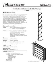
AMX24-LONLonWorks ® , Non-Spring Return, 24 VAccessoriesK-SAReversible ClampZG-100Universal Mounting BracketZG-101Universal Mounting BracketZG-103Universal Mounting BracketZG-104Universal Mounting BracketZ-SMAAM/SM to AM Retrofit Mounting BracketZG-AMACrank arm Adaptor KitAV8-25Universal Shaft ExtensionZG-JSA (-1, 2, 3) Jackshaft Adaptors for Hollow JackshaftsZS-100Weather Shield - SteelZS-150Weather Shield - PolycarbonateZS-260Explosion Proof HousingZS-300 (-1) (-5) NEMA 4X HousingTool-068 mm & 10 mm WrenchS1A, S2A Auxiliary Switch (es)P370Shaft Mount Auxiliary SwitchP…AFeedback PotentiometersSGA24Min positioners in NEMA 4 housingSGF24Min positioners for flush panel mountingADS-100 Analog to Digital SwitchNSV24 US Battery Back-Up ModuleZG-X40TransformerNOTE: When using AMX24-LON… actuators, only use accessories listed on this page.T–1T–~+2~+35 6 7MFTLONLONSensor scaling:The sensors can be scaled with the sensor plug-in (sensor table).Sensor Temperature range Resistance range ResolutionNi1000 –28 ... +98°C 850 ... 1600 Ω 1 ΩPT1000 –35 ... +155°C 850 ... 1600 Ω 1 ΩNTC–10 ... +160°C(depending on type)200 ... 60 kΩ 1 ΩSchema_LON_02M40024 - 05/10 - Subject to change. © Belimo Aircontrols (USA), Inc.Typical SpecificationProportional control damper actuators shall be electronic direct-coupled type, whichrequire no crank arm and linkage and be capable of direct mounting to a shaft up to1.05” diameter. Actuators shall have brushless DC motor technology and be protectedfrom overload at all angles of rotation. Actuators shall have reversing switch andmanual override on the cover. Run time shall be constant and independent of torque.Actuators shall be cULus listed, have a 5-year warranty, and be manufactured underISO 9001 International Quality Control Standards. Actuators shall be as manufacturedby Belimo.Wiring DiagramsVT–1T–~+2~+35 6 7MFTConnection without SensorLONLONVPossible connection of avoltmeter for checkingthe position feedback U.Schema_LON_01Connection with Passive Sensor, e.g. Pt1000, Ni1000, NTCT–1T–~+2~+35 6 7MFTLONLONRequirements forswitching contact:The switching contact must beable to accurately switch a currentof 16 mA @ 24 V.Connection with Switching Contact, e.g. Δp-monitorT–1~+235 6 7Possible input voltage range:0 ... 32 V (resolution 30 mV)Sensor scaling:The sensors can be scaled with thesensor plug-in (sensor table)Schema_LON_03Schema_LON_04T–~+MFTLONLONConnection with Active Sensor, e.g. 0...10 V @ 0...50° C800-543-9038 USA 866-805-7089 CANADA 203-791-8396 LATIN AMERICA240
AMX24-LONLonWorks ® , Non-Spring Return, 24 VFunctional Profile according to LonMARK ®The LON-capable damper actuator is certified by LonMARK ® . The actuator functionsare supplied with the LonWorks ® network as standardized network variablesaccording to LonMARK ® . The Node Object #0, the Damper Actuator Object #8110and the Open Loop SensorObject #1 are implemented in the actuator.Node object #0The node object contains the object status and object request functions.nviRequest SNVT_obj_requestInput variable for requesting the status of a particular object in the node.nvoStatusSNVT_obj_statusOutput variable that outputs the current status of a particular object in the node.nvoFileDirectory SNVT_addressOutput variable that shows information in the address range of the Neuron chip.Damper actuator object #8110The actuator object is used to map the functions of the MP actuators to theLONWORKS® network.nviRelStptSNVT_lev_percentThe nominal position is assigned to the actuator via this input variable. This variable isnormally linked to the output variable of an HVAC controller.nviActuateState SNVT_switchA preset position is assigned to the actuator via this input variable. Note on priority:The last variable that was active, either nviActuatorState or nviRelStpt, has priority.nviManOvrd SNVT_hvac_overidThese input variables can be used to manually override the actuator into a particularposition.nvoActualValue SNVT_lev_percentThis output variable shows the current actual position of the actuator and can be usedfor control circuit feedback or for displaying positions.nvoAbsAngle SNVT_angle_degThis output variable shows the current angle of rotation of the actuatoror the valve and can be used to display the position or for service purposes.nvoAbsAirFlow SNVT_flowThis output variable is inactive with the SR24ALON-5 rotary actuator and shows aconstant value of 65535 (this variable is only active in conjunction with LON-capableVAV controllers).Open loop sensor object #1A sensor can be connected to the rotary actuator. A passive resistance sensor (e.g.Ni1000), an active sensor (output 0 ... 32 V) or a switch (on/off) can be connected. Theopen loop sensor object transfers the measured sensor values to the LONWORKS®network.nvoSensorValue SNVT_xxxThis output variable shows the current sensor value. Depending on the connectedsensor, the output variable can be configured via the sensor plug-in and specificallyadapted to the system.The SNVT_... can be configured as:SNVT_temp_p SNVT_lev_percent SNVT_luxSNVT_temp SNVT_abs_humid SNVT_press_pSNVT_switch SNVT_enthalpy SNVT_smo_obscurSNVT_flow SNVT_ppm SNVT_powerSNVT_flow_p SNVT_rpm SNVT_elec_kwhNotesDetailed information on the functional profiles can be found on the website ofLonMARK ® (www.lonmark.org).M40024 - 05/10 - Subject to change. © Belimo Aircontrols (USA), Inc.241800-543-9038 USA 866-805-7089 CANADA 203-791-8396 LATIN AMERICA
AMX24-LONLonWorks ® , Non-Spring Return, 24 V451231 Direction of rotation switchSwitching overDirection of rotation changes2 Pushbutton and green LED displayOffNo voltage supply or malfunctionGreen, onOperationPress buttonSwitches on angle of rotation adaption followedby standard operation3 Service button for commissioning LONWORKS ® andyellow LED display for the LON statusOffThe SR24ALON-5 rotary actuator is connectedand ready for operation in theLONWORKS®network.Yellow, onNo application software is loaded in theSR24ALON-5.Yellow, flashingThe SR24ALON-5 is ready for operation but not(flashing interval 2 seconds) integrated in the LONWORKS ® network(unconfigured).Other flashing codes A fault is present in the SR24ALON-5.Press buttonService Pin Message is sent to theLONWORKS ® network.4 Gear disengagement switchPress buttonGear disengaged, motor stops, manual operationpossibleRelease buttonGear engaged, synchronisation starts, followedby standard operation5 Service plugFor connecting MFT parameterizing and service toolsM40024 - 05/10 - Subject to change. © Belimo Aircontrols (USA), Inc.800-543-9038 USA 866-805-7089 CANADA 203-791-8396 LATIN AMERICA242