Model VCD-43 - Greenheck
Model VCD-43 - Greenheck
Model VCD-43 - Greenheck

Create successful ePaper yourself
Turn your PDF publications into a flip-book with our unique Google optimized e-Paper software.
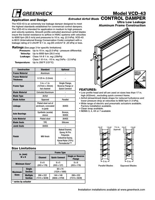
Application and DesignThe <strong>VCD</strong>-<strong>43</strong> is an extremely low leakage damper designed to meetthe highest standards established for commercial control dampers.The <strong>VCD</strong>-<strong>43</strong> is intended for application in medium to high pressureand velocity systems. Smooth profile extruded aluminum airfoil bladesinsure the lowest resistance to airflow in HVAC systems with velocitiesto 6000 fpm (30.5 m/s) and pressures to 10 in. wg. (2.5 kPa). <strong>VCD</strong>-<strong>43</strong>is IECC (International Energy Conservation Code) compliant with aleakage rating of 3 cfm/ft² @ 1 in. wg (55 cmh/m² @ .25 kPa) or less.Ratings (See page 3 for specific limitations)Pressure: Up to 10 in. wg (2.5 kPa) - pressure differential.Velocity: Up to 6000 fpm (30.5 m/s)Leakage: Class 1A @ 1 in. wg (.25kPa)Class 1 @ 4 in. -10 in. wg (1kPa - 2.5 kPa)Temperature: Up to 250°F (121ºC)<strong>Model</strong> <strong>VCD</strong>-<strong>43</strong>Extruded Airfoil Blade control damperUltra Low LeakageAluminum Frame ConstructionConstruction Standard OptionalFrame Material Aluminum -Frame MaterialThickness0.125 in. (3.2mm) -Frame Type5 in. x 1 in.(127mm x 25mm)hat channelSingle Flange,Reverse Flange orQuick ConnectBlade Material Extruded Aluminum -Blade Type Airfoil -Blade Action Opposed ParallelLinkagePlated steel out ofairstream, concealedin jamb304SSAxle BearingsSynthetic (acetal)sleeveBronze,304SSAxle Material Plated steel 304SSBlade Seals TPE SiliconeJamb Seals 304SS -FinishMIll finishBaked Enamel,Epoxy, Hi ProPolyester,Industrial Epoxy,Kynar/Hylar (70%)PermatectorSize Limitationsin. (mm)W x HMinimum Sizes*MaximumSizesSingleSectionMultipleSection* varies by actuatorChannel8 x 6(203 x 178)288 x 222(7315 x 5639)Frame TypeQuick Connect8 x 5(203 x 127)60 x 74(1524 x 1880)144 x 148(3658 x 3759)Single or ReverseFlange8 x 6(203 x 178)288 x 222(7315 x 5639)Features:• Low profile head and sill are used on sizes less than 17 in.high (<strong>43</strong>2mm) , excluding quick connect frame.• Airfoil (streamlined) blade shape for reduced turbulence andlower pressure drop at velocities to 6000 fpm (1.5 kPa).• Wide range of electric and pneumatic actuators available.Factory installation available.• Clean wrap available.• NEMA 3, 4, 4X or 7 available5 in.Parallel Blades1¼ in.(typical)5 in.Opposed BladesInstallation installations available at www.greenheck.com
Frame type optionsChannel FrameSingle Flange<strong>VCD</strong>-<strong>43</strong>Reverse Flange* Width and height is based on outsidedimension. W & H dimensions furnishedapproximately 1/4 in. (6mm) undersize.Quick Connect1 3/8 in.Note: When ordering the Quick Connect Frame, sizeis based on duct size ( or inside dimension of thedamper frame). Quick connect frame is actual size.1 3/8 in.
Pressure Drop Data<strong>VCD</strong>-<strong>43</strong>This pressure drop testing was conducted in accordance with AMCA Standard 500-D using the threeconfigurations shown. All data has been corrected to represent standard air at a density of .075 lb/ft 3 (1.2 kg/m 3 ).Actual pressure drop found in any HVAC system is a combination of many factors. This pressure drop information5D6Dalong with an analysis of other system influences should be used to estimate actual pressure losses for a damperinstalled in a given HVAC system.AMCA Test FiguresFigure 5.2 Illustrates a ducted damper exhausting air into an open area. This configuration has a lower pressuredrop than Figure 5.5 because entrance losses are minimized by a straight duct run upstream of the damper.5DD4 (W) (H)3.14Figure 5.3 Illustrates a fully ducted damper. This configuration has the lowest pressure drop of the three testconfigurations because entrance 5D and exit losses are minimized 6D by straight duct runs upstream and downstream ofthe damper.5D6D5DD 4 (W) (H)Figure 5.5 Illustrates a plenum 5D3.14mounted damper. This configuration has the highest pressure drop because ofextremely high entrance and exit losses due to the sudden changes of area in the system.D4 (W) (H)3.14
AMCA Certified Pressure Drop Data<strong>VCD</strong>-<strong>43</strong>5D<strong>Greenheck</strong> Fan 6D Corporation certifies that the model<strong>VCD</strong>-<strong>43</strong> shown herein is licensed to bear the AMCA Seal.The ratings shown are based on tests and proceduresperformed in accordance with AMCA Publication 511and comply with the requirements of the AMCA CertifiedRatings Programs.The AMCA Certified Ratings Sealapplies to Air Leakage and Air Performance ratings.AMCA 5.25DD4 (W) (H)3.1412 in. x 12 in. (305mm x 305mm) 24 in. x 24 in. (610mm x 610mm) 36 in. x 36 in. (914mm x 914mm)Velocity (fpm)Pressure Drop(in. wg)Velocity (fpm)Pressure Drop(in. wg)Velocity (fpm)Pressure Drop(in. wg)500 0.01 500 0.01 500 0.011000 0.06 1000 0.04 1000 0.031500 0.13 1500 0.10 1500 0.062000 0.23 2000 0.18 2000 0.122500 0.35 2500 0.28 2500 0.183000 0.50 3000 0.40 3000 0.263500 0.68 3500 0.54 3500 0.354000 0.88 4000 0.70 4000 0.4612 in. x 48 in. (305mm x 1219mm)Velocity (fpm)Pressure Drop(in. wg)500 0.011000 0.041500 0.102000 0.172500 0.263000 0.383500 0.524000 0.6848 in. x 12 in. (1219mm x 305mm)Velocity (fpm)Pressure Drop(in. wg)500 0.011000 0.031500 0.062000 0.102500 0.163000 0.233500 0.304000 0.39AMCA 5.35D6D12 in. x 12 in. (305mm x 305mm) 24 in. x 24 in. (610mm x 610mm) 36 in. x 36 in. (914mm x 914mm)Velocity (fpm)Pressure 5D Drop(in. wg)D4 (W) (H)3.141000 5D 0.03 6D 1000 0.02 1000 0.013500 5D 0.39 3500 0.26 3500 0.134000 0.51 4000 0.34 4000 0.17D 4 (W) (H)3.14AMCA 5.5Velocity (fpm)Pressure Drop(in. wg)Velocity (fpm)Pressure Drop(in. wg)500 0.01 500 0.01 500 0.011500 0.07 1500 0.04 1500 0.022000 0.14 2000 0.08 2000 0.042500 0.21 2500 0.13 2500 0.063000 0.29 3000 0.19 3000 0.0912 in. x 48 in. (305mm x 1219mm)Velocity (fpm)Pressure Drop(in. wg)500 0.011000 0.031500 0.062000 0.112500 0.173000 0.253500 0.344000 0.4548 in. x 12 in. (1219mm x 305mm)Velocity (fpm)Pressure Drop(in. wg)500 0.011000 0.021500 0.042000 0.082500 0.123000 0.183500 0.244000 0.3112 in. x 12 in. (305mm x 305mm) 24 in. x 24 in. (610mm x 610mm) 36 in. x 36 in. (914mm x 914mm)Velocity (fpm)Pressure Drop(in. wg)Velocity (fpm)Pressure Drop(in. wg)Velocity (fpm)Pressure Drop(in. wg)500 0.04 500 0.03 500 0.031000 0.14 1000 0.12 1000 0.101500 0.31 1500 0.27 1500 0.222000 0.55 2000 0.48 2000 0.392500 0.86 2500 0.75 2500 0.613000 1.23 3000 1.07 3000 0.873500 1.67 3500 1.47 3500 1.194000 2.19 4000 1.91 4000 1.5612 in. x 48 in. (305mm x 1219mm)Velocity (fpm)Pressure Drop(in. wg)500 0.031000 0.111500 0.252000 0.462500 0.723000 1.053500 1.<strong>43</strong>4000 1.8748 in. x 12 in. (1219mm x 305mm)Velocity (fpm)Pressure Drop(in. wg)500 0.031000 0.111500 0.262000 0.462500 0.723000 1.023500 1.404000 1.83
leakageselection criteriaAir leakage is based on operation between 32°F (0°C) and 120°F (49°C).Tested for leakage in accordance with ANSI/AMCA Standard 500-D, Figure 5.5.Tested for air performance in accordance with ANSI/AMCA Standard 500-D, Figures 5.2, 5.3 and 5.5.TorqueData are based on a torque of 5.0 in.lb./ft² (0.56 N·m) applied to close and seat the damper during the test.<strong>VCD</strong>-<strong>43</strong>Leakage Class*MaximumDamper Width1 in. wg(0.25 kPa)4 in. wg(1 kPa)8 in. wg(2 kPa)10 in. wg(2.5 kPa)60 in. (1524mm) 1A 1 1 1* applies to opposed blades only<strong>Greenheck</strong> Fan Corporation certifies that the model<strong>VCD</strong>-<strong>43</strong> shown herein is licensed to bear the AMCASeal. The ratings shown are based on tests andprocedures performed in accordance with AMCAPublication 511 and comply with the requirementsof the AMCA Certified Ratings Programs.The AMCACertified Ratings Seal applies to Air Leakage and AirPerformance ratings.*Leakage Class DefinitionsThe maximum allowable leakage is defined as the following:• Leakage Class 1A - 3 cfm/ft 2 @ 1 in. wg (class 1A is onlydefined at 1 in. wg).• Leakage Class 1- 4 cfm/ft 2 @ 1 in. wg- 8 cfm/ft 2 @ 4 in. wg- 11 cfm/ft 2 @ 8 in. wg- 12.6 cfm/ft 2 @ 10 in. wgVelocity Limitations7460Damper Height (in.)4836246000fpm5000fpm4000fpm3500fpm3000fpm1200 12 24 36 48Damper Width (in.)60
assembliesspecificationsMulti-Section AssemblyDampers larger than the maximum single section size, will be made up of a multiple of equal size sections. Multiple sectiondampers can be jackshafted together so that all sections operate together as shown below.NOTE: Dampers larger than 60 in. x74 in. (1524mm x 1880mm) are not intended to be structurally self supporting. Additionalhorizontal bracing is recommended to support the weight of the damper and vertical bracing should be installed asrequired to hold against system pressure.SpecificationsControl dampers meeting the following specifications shallbe furnished and installed where shown on plans and/or asdescribed in schedules.Dampers shall consist of: heavy gauge aluminum frame(0.125 in. [3.2mm] thick) with 5 in. (127mm) depth formedinto a structural hat channel shape; airfoil shaped, extrudedaluminum blades (0.063 in. [1.6mm] thick) with metal bladeto blade overlap (seal to seal only contact is not acceptable);blades shall be completely symmetrical relative to their axlepivot point, presenting identical resistance to airflow andoperation in either direction through the damper (blades thatare non-symmetrical relative to their axle pivot point or utilizeblade stops larger than 1 /2 in. (13mm) are unacceptable); 1 /2in. (13mm) dia. plated steel axles turning in synthetic (acetal)sleeve bearings; TPE blade seals; flexible stainless steel jambseals; and external (out of the airstream) blade-to-bladelinkage.Damper manufacturer's printed application and performancedata including pressure, velocity and temperature limitationsshall be submitted for approval showing damper suitablefor pressures to 10 in. wg (2.5 kPa), velocities to 6000 fpm(30.5m/s) and temperatures to 250°F (121ºC).Damper manufacturer's printed performance data showingstandard air leakage less than 6 cfm/ft 2 @ 4 in. (.003 m 3 /s@ 1 kPa) wg in either direction through the damper shall besubmitted for approval.Testing and ratings shall be developed in accordance withthe latest edition of AMCA Standard 500-D.Basis of design is <strong>Greenheck</strong> <strong>VCD</strong>-<strong>43</strong>.Copyright © 2013 <strong>Greenheck</strong> Fan Corporation<strong>VCD</strong>-<strong>43</strong> Rev. 12 January 2013