Multi-Cyclone Dust Collectors - Clarage
Multi-Cyclone Dust Collectors - Clarage
Multi-Cyclone Dust Collectors - Clarage

You also want an ePaper? Increase the reach of your titles
YUMPU automatically turns print PDFs into web optimized ePapers that Google loves.
<strong>Clarage</strong> <strong>Collectors</strong><br />
inlet guide vanes<br />
The inlet guide vanes (5) are separately<br />
cast and are held in place by support<br />
on the gas outlet tube (6). They fit<br />
securely in place inside the collecting<br />
tube keeping the outlet tube centered.<br />
Inlet guide vanes are designed to give<br />
the gas maximum centrifugal action<br />
on its spiraling path down the tube<br />
toward the dust discharge boot (7).<br />
Inlet guide vanes are replaceable by<br />
splitting them in half. Each vane has<br />
two notches for this purpose.<br />
<strong>Dust</strong> Discharge boot<br />
The cast-iron dust discharge boot is<br />
retained at the lower end of the collecting<br />
tube by two boot straps (8).<br />
The boot straps in turn are bolted in<br />
place at the top of the collecting tube<br />
with two of the studs used to connect<br />
the assembly to the bottom tube<br />
sheets. Since the boot is subject to<br />
the greatest wear, it has been designed<br />
for easy replacement. This design<br />
allows greater cost savings than<br />
replacement of the entire collecting<br />
tube, as with competitive designs having<br />
the boot and tube as an integral<br />
assembly. The dust discharge boot has<br />
three peripheral slots where collected<br />
dust is discharged by inertial and<br />
centrifugal force out of the tube,<br />
immediately prior to the vortex<br />
reversal of the gas at the tube bottom.<br />
outlet recovery<br />
vanes<br />
Recovery vanes (9) are used at the<br />
lower end of the gas outlet tube in<br />
certain applications. These vanes are<br />
used to recover the rotational energy<br />
of the exiting gas, thereby increasing<br />
the total capacity of each collecting<br />
tube. Recovery vanes are not recommended<br />
where the incoming gas has<br />
a characteristic, such as heavy oil<br />
or bark-fired combinations. Outlet<br />
recovery vanes have the efficiency<br />
benefits of permitting a smaller<br />
collector for a given gas flow.<br />
outlet tubes<br />
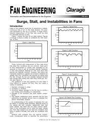
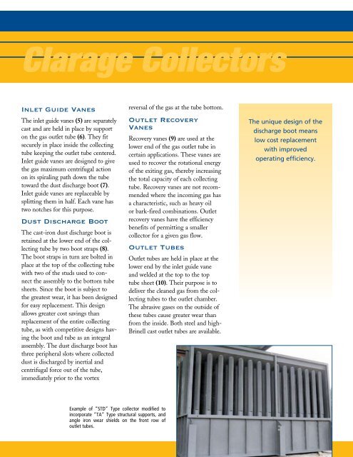
Example of “STD” Type collector modified to<br />
incorporate “TA” Type structural supports, and<br />
angle iron wear shields on the front row of<br />
outlet tubes.<br />
Outlet tubes are held in place at the<br />
lower end by the inlet guide vane<br />
and welded at the top to the top<br />
tube sheet (10). Their purpose is to<br />
deliver the cleaned gas from the collecting<br />
tubes to the outlet chamber.<br />
The abrasive gases on the outside of<br />
these tubes cause greater wear than<br />
from the inside. Both steel and high-<br />
Brinell cast outlet tubes are available.<br />
The unique design of the<br />
discharge boot means<br />
low cost replacement<br />
with improved<br />
operating efficiency.