FAN ENGINEERING - Clarage
FAN ENGINEERING - Clarage
FAN ENGINEERING - Clarage

You also want an ePaper? Increase the reach of your titles
YUMPU automatically turns print PDFs into web optimized ePapers that Google loves.
<strong>FAN</strong> <strong>ENGINEERING</strong><br />
Information and Recommendations for the Engineer<br />
FE-2400<br />
Fan Performance<br />
Characteristics of Centrifugal Fans<br />
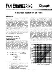
Introduction<br />
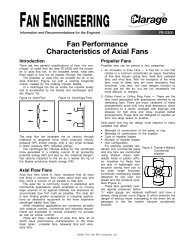
There are two general classifications of fans: the propeller<br />
or axial flow fan (see FE-2300) and the centrifugal or<br />
radial flow fan. In the broadest sense, what sets them<br />
apart is how the air passes through the impeller.<br />
The propeller or axial flow fan propels the air in an<br />
axial direction (Figure 1a) with a swirling tangential<br />
motion created by the rotating impeller blades.<br />
In a centrifugal fan the air enters the impeller axially<br />
and is accelerated by the blades and discharged radially<br />
(Figure 1b). The one exception to this is the tangential/transverse<br />
fan where the air enters and discharges<br />
radially through the impeller.<br />
The axial flow fan increases the air velocity through<br />
rotational or tangential force which produces velocity<br />
pressure (VP), kinetic energy, with a very small increase<br />
in static pressure (SP), potential energy.<br />
The centrifugal fan induces airflow by the centrifugal<br />
force generated in a rotating column of air producing<br />
potential energy (SP) and also by the rotational (tangential)<br />
velocity imparted to the air as it leaves the tip of<br />
the blades producing kinetic energy (VP).<br />
Figure 2 illustrates the components that make up a<br />
typical centrifugal fan and covers the common terminology<br />
of these components.<br />
Figure 1a. Axial Flow<br />
Figure 1b. Centrifugal<br />
Flow<br />
Figure 2. Terminology for Centrifugal Fan Components<br />
Wheel Types<br />
Centrifugal fans may be classified into three basic types<br />
according to blade configuration:<br />
1. Forward curve<br />
2. Backward inclined<br />
3. Radial or straight blade<br />
Each type has its own application range and limits.<br />
Modifications of these basic types include radial tip,<br />
mixed flow, and tangential flow.<br />
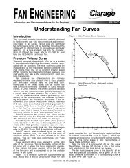
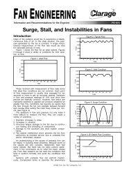
The tip speed required to produce the required air<br />
particle velocity varies substantially with the type of<br />
blade used. Figures 3a, 3b, and 3c (Figure 3) show vector<br />
diagrams of forces in forward curve, backward curve,<br />
and radial blade impellers, respectively. Vector V1 represents<br />
the rotational or tangential velocity, and V2 represents<br />
the radial velocity of the airflow between the<br />
blades with respect to the various blade shapes.<br />
Figure 3. Wheel Vector Diagrams<br />
V1<br />
R<br />
V2<br />
V1<br />
3a. 3b. 3c.<br />
Forward Curve Backward Curve Radial<br />
R<br />
V2<br />
V1<br />
R<br />
V2<br />
Vector R represents the resultant velocity for each of<br />
these blade shapes. Note that R for the forward curve<br />
impeller is the largest with the backward inclined impeller<br />
the smallest, while the radial blade fan lies somewhere<br />
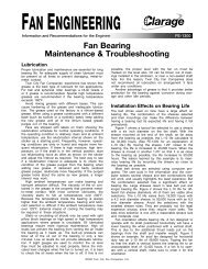
in between. This relationship is best illustrated in<br />
Figure 4, which shows a typical tip speed/static pressure<br />
relationship for various types of centrifugal fans.<br />
©2000 Twin City Fan Companies, Ltd.
Figure 4. Tip Speed/Static Pressure Relationship<br />
RPM — HUNDREDS<br />
STATIC PRESSURE — IN. W.G.<br />
45<br />
40<br />
35<br />
30<br />
25<br />
20<br />
15<br />
10<br />
5<br />
0.9<br />
0.8<br />
0.7<br />
0.6<br />
0.5<br />
0.4<br />
0.3<br />
0.2<br />
0.1<br />
Forward Curve Fans<br />
WHEEL DIA. INCHES<br />
2 3<br />
4<br />
F R B<br />
These fans are sometimes known as “volume,” “squirrel<br />
cage,” or “sirocco” blowers. The impeller blades are<br />
small and numerous with a pronounced curvature and<br />
short chord length. The concave blade curvature faces<br />
the direction of rotation. These fans operate at relatively<br />
low speeds and pressures (reference Figure 4)<br />
which permits light construction of the impeller, shaft,<br />
bearings, and housing.<br />
6<br />
8<br />
10<br />
12<br />
16<br />
20<br />
30<br />
BLADE INCLINATION<br />
F = FORWARD<br />
R = RADIAL<br />
B = BACKWARD<br />
1 2 3 4<br />
TIP SPEED — FPM (THOUSANDS)<br />
The forward curve fan is used to deliver high air volumes<br />
against static pressures up to 6" water gauge.<br />
However, the majority of applications are for pressures of<br />
3" water gauge or less. Note the pronounced dip (stall)<br />
in the static pressure curve (Figure 5b). Any selection to<br />
the left of the 40% free delivery point (peak) will result<br />
in an unstable pulsating airflow that will lead to impeller<br />
and structural damage. Even though good peak efficiencies<br />
are on either side of the peak, selections should be<br />
limited to 45% or greater of free delivery.<br />
Interestingly, in parallel installations, if selected too<br />
close to peak, forward curve fans exhibit a tendency not<br />
to share the load equally and become unstable. These<br />
selections should be limited to 55% or greater of free<br />
delivery.<br />
The advantage of the forward curve fan is its low speed<br />
and quiet operation. The light construction results in a low<br />
cost fan and its relatively high airflow results in a small<br />
fan requiring minimum space, making it ideal for the residential<br />
and commercial heating and cooling market.<br />
Disadvantages are that its high horsepower requirements<br />
at or near free delivery (note the rising power<br />
curve in Figure 5b) and its light construction limit its<br />
suitability for most industrial requirements.<br />
Highly dependent on the housing for performance, the<br />
forward curve impeller is not suitable for plug or plenum<br />
fan applications. Without a housing the forward curve<br />
impeller becomes unstable and exhibits a relatively poor<br />
performance.<br />
Backward Inclined Fans<br />
These are sometimes called “load limiting” or “non-overloading”<br />
fans. The impeller blades are larger and heavier<br />
than forward curve blades, usually number from eight to<br />
twelve, and are inclined away from the direction of rotation.<br />
They are standardly offered in three blade shapes:<br />
1. Flat single thickness (Figure 6a)<br />
2. Curved single thickness (Figure 6b)<br />
3. Curved airfoil (Figure 6c)<br />
Figure 6. Backward Inclined Fans<br />
Figure 5a. Typical Forward Curve Fan<br />
6a. Flat Single Thickness, BI<br />
Figure 5b. Characteristic Performance of Forward Curve Fans<br />
100<br />
PERCENT OF NO FLOW STATIC PRESSURE<br />
HORSEPOWER AND EFFICIENCY<br />
90<br />
80<br />
70<br />
60<br />
50<br />
40<br />
30<br />
20<br />
10<br />
HORSEPOWER<br />
STATIC EFFICIENCY<br />
TOTAL PRESSURE<br />
TOTAL EFFICIENCY<br />
STATIC PRESSURE<br />
6b. Curved Single Thickness, BC<br />
0<br />
0 10 20 30 40 50 60 70 80 90 100<br />
PERCENT OF FREE DELIVERY<br />
6c. Curved Airfoil, BIA<br />
2 Fan Engineering FE-2400
Backward inclined fans are used to deliver medium<br />
to high airflow at static pressures up to 20" water<br />
gauge. Pressures up to 40" water gauge are attainable<br />
with special construction.<br />
The normal selection range for quiet, efficient performance<br />
is from 40% to 85% of free delivery (Figure 7).<br />
While these fans do not exhibit a deep stall range like<br />
the forward curve fan, there is a range of instability left<br />
of peak. The single thickness blades are more sensitive<br />
to the breakaway airflow in this area than the airfoil and<br />
should be selected to the right of peak.<br />
Figure 7 shows the characteristic of a flat blade<br />
design; however, it typifies the characteristics of the<br />
entire family of backward inclined blade shapes. Only<br />
subtle differences exist between their static pressure<br />
curves.<br />
Figure 7. Characteristic Performance of Backward Inclined<br />
Flat Blade Fans<br />
Radial Blade Fans<br />
“Steel plate” or “paddle wheel” are two of the common<br />
names for radial blade fans. The impeller blades are<br />
generally narrower, deeper and heavier than forward<br />
curve and backward inclined blades. A radial blade<br />
impeller usually comprises six to twelve equally spaced<br />
flat blades extending radially from the center of the hub.<br />
These impellers are generally of simple design that lends<br />
itself to rugged construction and offers a minimum of<br />
ledges, etc., for the accumulation of dust or sticky materials.<br />
There are more variations of the radial blade fans<br />
than the forward curve and backward inclined types.<br />
Three of the more common impellers are illustrated in<br />
Figure 8.<br />
Figure 8. Common Radial Blade Impellers<br />
100<br />
PERCENT OF NO FLOW STATIC PRESSURE<br />
HORSEPOWER AND EFFICIENCY<br />
90<br />
80<br />
70<br />
60<br />
50<br />
40<br />
30<br />
20<br />
10<br />
HORSEPOWER<br />
TOTAL EFFICIENCY<br />
TOTAL PRESSURE<br />
STATIC PRESSURE<br />
STATIC EFFICIENCY<br />
0<br />
0 10 20 30 40 50 60 70 80 90 100<br />
PERCENT OF FREE DELIVERY<br />
An attractive feature of the backward inclined types<br />
is the non-overloading characteristic of their horsepower<br />
curves. As Figure 7 illustrates, the horsepower increases<br />
to a maximum as airflow increases, and then drops off<br />
again toward free delivery. This means that a motor<br />
selected to accommodate the peak horsepower will not<br />
overload, despite variations in the system resistance or<br />
airflow, as long as the fan speed remains constant.<br />
Typically the flat bladed design has efficiencies of<br />
about 82%, while the curved blade and airfoil designs<br />
approach 86% and 90%, respectively.<br />
The backward inclined “family” of fans has the highest<br />
operating speeds of all the centrifugal fans (Figure<br />
4). While this is a desirable feature for direct connection<br />
to modern “high speed” motor or turbine drives, it<br />
comes with a price. Their high operating speed requires<br />
heavier construction and precision balancing, making<br />
them fairly expensive compared to forward curve fans.<br />
Also, the close running clearances required to maintain<br />
fan performance makes them unsuitable for material<br />
handling. However, in single thickness blade construction<br />
they can be used in light dust and corrosive air.<br />
These fans are used primarily in the industrial market<br />
for ventilation, clean side of commercial air cleaning<br />
devices, furnace draft and large commercial heating and<br />
cooling units. The air leaving the backward inclined<br />
impeller has less of its total energy in the form of velocity<br />
pressure than does the air leaving a forward curve<br />
impeller. Because more of its energy is in the form of<br />
static pressure, a backward inclined impeller loses less<br />
energy in the process of converting from velocity pressure<br />
to static pressure in the housing. Therefore, a<br />
backward inclined impeller can operate quite satisfactorily<br />
without a housing, making it suitable for specialty<br />
fans such as plug fans, plenum fans, and in-line centrifugal<br />
fans, whose characteristics are all similar to<br />
Figure 7, just slightly less efficient.<br />
8a. 8b. 8c.<br />
OW/BW AW RT<br />
Radial Blade Air Wheel Radial Tip<br />
The open wheel (OW), paddle wheel; and the backplate<br />
wheel (BW), steel plate, are the most common of<br />
the radial blade impellers, and their typical performance<br />
characteristics are shown in Figure 9. These fans are<br />
generally selected to operate from 35% to 80% of free<br />
delivery. However, it should be noted that these fans<br />
can, and do, operate quite successfully left of peak,<br />
down to approximately 20% of free delivery.<br />
Figure 9. Characteristic Performance of Radial Blade Fans<br />
PERCENT OF NO FLOW STATIC PRESSURE<br />
HORSEPOWER AND EFFICIENCY<br />
100<br />
90<br />
80<br />
70<br />
60<br />
50<br />
40<br />
30<br />
20<br />
10<br />
STATIC EFFICIENCY<br />
HORSEPOWER<br />
TOTAL PRESSURE<br />
TOTAL EFFICIENCY<br />
STATIC PRESSURE<br />
0<br />
0 10 20 30 40 50 60 70 80 90 100<br />
PERCENT OF FREE DELIVERY<br />
From Figure 4 it can be seen that these are medium<br />
speed fans and are used to deliver low air volumes at<br />
medium to high pressure. The main advantage of the<br />
radial blade fan lies in its simple but rugged construction.<br />
They are ideal for high static pressure applications<br />
and for handling airstreams containing a high level of<br />
particulate.<br />
Some of the disadvantages are that they generate<br />
more noise than forward curve and backward inclined<br />
fans, primarily because of the impeller design and high<br />
operating velocities and they exhibit the same rising<br />
horsepower characteristic as the forward curve fans.<br />
Because they are low volume fans, larger sizes are<br />
generally required, taking up a larger installation space.<br />
Fan efficiencies are lower than both the forward curve<br />
and backward inclined type, but this is generally offset<br />
by their ability to adapt to harsh environments.<br />
3 Fan Engineering FE-2400
For higher efficiencies most manufacturers offer some<br />
variation of the air wheel (AW) impeller, Figure 8b, to<br />
operate in the same housing as the straight radial blade<br />
impellers. For even higher efficiencies and airflow, manufacturers<br />
also offer a radial tip (RT) impeller; however,<br />
in most cases the radial tip impeller operates in a housing<br />
similar to the backward inclined design. The radial<br />
tip design fills the gap between the clean air backward<br />
inclined fans and the more rugged radial blade fans.<br />
Both the air wheel and the radial tip impellers are<br />
ideal for contaminated airstreams but neither is intended<br />
for bulk material handling. Both impellers have pressure<br />
characteristics similar to the backward inclined impellers<br />
and a horsepower characteristic similar to the radial<br />
blade and forward curve impellers. Unlike the straight<br />
radial blade impellers these two impeller designs do<br />
exhibit some instability left of peak and should always<br />
be selected to the right of peak.<br />
By and large, the radial blade series of fans are used<br />
exclusively in the industrial market for handling and conveying<br />
various process materials and gases. They are<br />
used for “high pressure” air systems and for combustion<br />
air. Generally speaking, they are furnished in belt drive<br />
arrangements due to the high shock loads and harsh<br />
environments to which they are exposed.<br />
CLARAGE | www.CLARAGE.com<br />
2335 Columbia Highway | Pulaski, TN 38478 | Phone: 931-363-2667 | Fax: 931-363-3155