FAN ENGINEERING - Clarage
FAN ENGINEERING - Clarage
FAN ENGINEERING - Clarage

You also want an ePaper? Increase the reach of your titles
YUMPU automatically turns print PDFs into web optimized ePapers that Google loves.
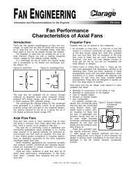
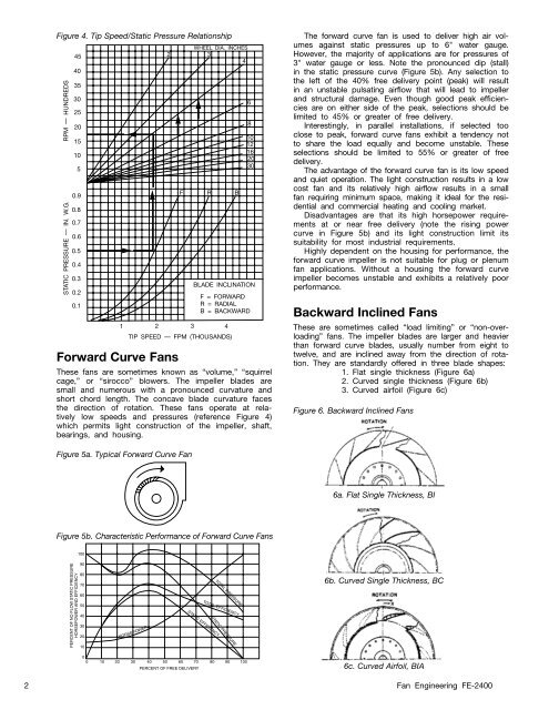
Figure 4. Tip Speed/Static Pressure Relationship<br />
RPM — HUNDREDS<br />
STATIC PRESSURE — IN. W.G.<br />
45<br />
40<br />
35<br />
30<br />
25<br />
20<br />
15<br />
10<br />
5<br />
0.9<br />
0.8<br />
0.7<br />
0.6<br />
0.5<br />
0.4<br />
0.3<br />
0.2<br />
0.1<br />
Forward Curve Fans<br />
WHEEL DIA. INCHES<br />
2 3<br />
4<br />
F R B<br />
These fans are sometimes known as “volume,” “squirrel<br />
cage,” or “sirocco” blowers. The impeller blades are<br />
small and numerous with a pronounced curvature and<br />
short chord length. The concave blade curvature faces<br />
the direction of rotation. These fans operate at relatively<br />
low speeds and pressures (reference Figure 4)<br />
which permits light construction of the impeller, shaft,<br />
bearings, and housing.<br />
6<br />
8<br />
10<br />
12<br />
16<br />
20<br />
30<br />
BLADE INCLINATION<br />
F = FORWARD<br />
R = RADIAL<br />
B = BACKWARD<br />
1 2 3 4<br />
TIP SPEED — FPM (THOUSANDS)<br />
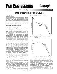
The forward curve fan is used to deliver high air volumes<br />
against static pressures up to 6" water gauge.<br />
However, the majority of applications are for pressures of<br />
3" water gauge or less. Note the pronounced dip (stall)<br />
in the static pressure curve (Figure 5b). Any selection to<br />
the left of the 40% free delivery point (peak) will result<br />
in an unstable pulsating airflow that will lead to impeller<br />
and structural damage. Even though good peak efficiencies<br />
are on either side of the peak, selections should be<br />
limited to 45% or greater of free delivery.<br />
Interestingly, in parallel installations, if selected too<br />
close to peak, forward curve fans exhibit a tendency not<br />
to share the load equally and become unstable. These<br />
selections should be limited to 55% or greater of free<br />
delivery.<br />
The advantage of the forward curve fan is its low speed<br />
and quiet operation. The light construction results in a low<br />
cost fan and its relatively high airflow results in a small<br />
fan requiring minimum space, making it ideal for the residential<br />
and commercial heating and cooling market.<br />
Disadvantages are that its high horsepower requirements<br />
at or near free delivery (note the rising power<br />
curve in Figure 5b) and its light construction limit its<br />
suitability for most industrial requirements.<br />
Highly dependent on the housing for performance, the<br />
forward curve impeller is not suitable for plug or plenum<br />
fan applications. Without a housing the forward curve<br />
impeller becomes unstable and exhibits a relatively poor<br />
performance.<br />
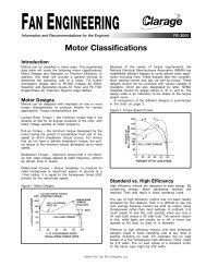
Backward Inclined Fans<br />
These are sometimes called “load limiting” or “non-overloading”<br />
fans. The impeller blades are larger and heavier<br />
than forward curve blades, usually number from eight to<br />
twelve, and are inclined away from the direction of rotation.<br />
They are standardly offered in three blade shapes:<br />
1. Flat single thickness (Figure 6a)<br />
2. Curved single thickness (Figure 6b)<br />
3. Curved airfoil (Figure 6c)<br />
Figure 6. Backward Inclined Fans<br />
Figure 5a. Typical Forward Curve Fan<br />
6a. Flat Single Thickness, BI<br />
Figure 5b. Characteristic Performance of Forward Curve Fans<br />
100<br />
PERCENT OF NO FLOW STATIC PRESSURE<br />
HORSEPOWER AND EFFICIENCY<br />
90<br />
80<br />
70<br />
60<br />
50<br />
40<br />
30<br />
20<br />
10<br />
HORSEPOWER<br />
STATIC EFFICIENCY<br />
TOTAL PRESSURE<br />
TOTAL EFFICIENCY<br />
STATIC PRESSURE<br />
6b. Curved Single Thickness, BC<br />
0<br />
0 10 20 30 40 50 60 70 80 90 100<br />
PERCENT OF FREE DELIVERY<br />
6c. Curved Airfoil, BIA<br />
2 Fan Engineering FE-2400