download - MPW MED. INSTRUMENTS Spółdzielnia Pracy
download - MPW MED. INSTRUMENTS Spółdzielnia Pracy
download - MPW MED. INSTRUMENTS Spółdzielnia Pracy

You also want an ePaper? Increase the reach of your titles
YUMPU automatically turns print PDFs into web optimized ePapers that Google loves.
centrifuge - Cat. No.:<br />
user manual - Cat. No.:<br />
10380, 10380R<br />
20380/R/ENG<br />
1<br />
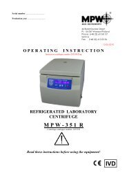
U S E R M A N U A L<br />
LABORATORY CENTRIFUGE<br />
<strong>MPW</strong>-380/R<br />
Read this before use!<br />
<strong>MPW</strong> Med. instruments, 46 Boremlowska Street, 04-347 Warsaw/Poland<br />
tel. +48 22 610 81 07 (service), fax +48 22 610 55 36<br />
mpw@mpw.pl, www.mpw.pl<br />
2012-06-12
Warning sings and hazard icons.<br />
WARNING!<br />
Warning of potential injury or health risk.<br />
DANGER!<br />
Risk of electric shock with potential for severe injury or death as a consequence.<br />
DANGER!<br />
Biohazard with potential for risk to health or death as a consequence.<br />
DANGER!<br />
Risk of explosion with potential for severe injury or death as a consequence.<br />
Statement of Conformity:<br />
The following machine is in accordance with the regulations of the EU Directive 98/79/EC and with the<br />
harmonized standards PN-EN 61010-1 and PN-EN 61010-2-020.<br />
2
Contents<br />
1. APPLICATION. ..................................................................................................................................................................... 5<br />
2. TECHNICAL DATA. .............................................................................................................................................................. 5<br />
2.1. ACCESSORIES. ................................................................................................................................................................... 6<br />
2.1.1. Basic accessories (delivered with every centrifuge). ................................................................................................. 6<br />
2.1.2. Optional accessories. ................................................................................................................................................. 6<br />
2.2. EXPLOITATION MATERIALS. ............................................................................................................................................. 9<br />
3. INSTALLATION. .................................................................................................................................................................. 10<br />
3.1. UNPACKING OF THE CENTRIFUGE. ................................................................................................................................. 10<br />
3.2. LOCATION. ....................................................................................................................................................................... 10<br />
3.3. CONNECTION TO MAINS. ................................................................................................................................................. 10<br />
3.4. CURRENT PROTECTION. .................................................................................................................................................. 10<br />
4. DESCRIPTION OF THE CENTRIFUGE. ......................................................................................................................... 11<br />
4.1. GENERAL DESCRIPTION. ................................................................................................................................................. 11<br />
4.2. SERVICE ELEMENTS. ....................................................................................................................................................... 11<br />
5. SAFE WORKING CONDITIONS. ...................................................................................................................................... 12<br />
5.1. SERVICING PERSONNEL. .................................................................................................................................................. 12<br />
5.2. GUARANTEE AND OPERATIONAL USE PERIOD. ............................................................................................................... 12<br />
5.3. SAFEKEEPING PERIOD. .................................................................................................................................................... 12<br />
5.4. HINTS ON CENTRIFUGING. .............................................................................................................................................. 12<br />
5.5. HAZARDS AND PRECAUTIONS .......................................................................................................................................... 13<br />
6. OPERATION OF THE CENTRIFUGE. ............................................................................................................................. 14<br />
6.1. MOUNTING OF THE ROTOR AND ACCESSORIES. ............................................................................................................. 14<br />
6.2. CONSTRUCTION AND SAFETY MEASURES. ...................................................................................................................... 15<br />
6.3. DRIVE. .............................................................................................................................................................................. 15<br />
6.4. DATA INPUT AND OUTPUT. .............................................................................................................................................. 15<br />
6.5. CONTROLS. ...................................................................................................................................................................... 15<br />
6.6. SAFETY DEVICES. ............................................................................................................................................................ 16<br />
6.6.1. Cover lock. ............................................................................................................................................................... 16<br />
6.6.2. Unbalanced load checking system. ......................................................................................................................... 16<br />
6.6.3. Rotor installation and software compatibility verification unit. ............................................................................ 16<br />
6.6.4. Rest state inspection. ............................................................................................................................................... 16<br />
6.6.5. Checking of excessive temperature. ........................................................................................................................ 16<br />
7. DESCRIPTION OF THE CENTRIFUGE OPERATING ELEMENTS. .......................................................................... 17<br />
7.1. CONTROL PANEL. ............................................................................................................................................................ 17<br />
7.2. DISPLAY. .......................................................................................................................................................................... 18<br />
7.2.1. Variations of the main screen ................................................................................................................................. 19<br />
7.3. SETTING UP PARAMETERS ............................................................................................................................................... 19<br />
7.4. DESCRIPTION OF ZONES .................................................................................................................................................. 21<br />
7.4.1. Speed ........................................................................................................................................................................ 21<br />
7.4.2. Rcf ............................................................................................................................................................................ 21<br />
7.4.3. Time ......................................................................................................................................................................... 22<br />
7.4.4. Temp (Temperature) ............................................................................................................................................... 23<br />
7.4.5. Prog (User’s programs) ........................................................................................................................................... 23<br />
7.4.6. List of the user programs ........................................................................................................................................ 24<br />
7.4.7. Program of preliminary refrigerating .................................................................................................................... 25<br />
7.4.8. Changing acceleration/deceleration characteristics (numbers ACC/DEC 10 19) ............................................. 26<br />
7.4.9. Rotor/ Bucket ........................................................................................................................................................... 26<br />
7.4.10. List of rotors .......................................................................................................................................................... 26<br />
7.5. PARA – ZONE OF SETUP OF OPERATIONS’ PARAMETERS ................................................................................................ 27<br />
7.5.1. Description of the function in the Para fold ........................................................................................................... 28<br />
7.5.2. Acceleration and Deceleration characteristics. ...................................................................................................... 28<br />
7.5.3. Radius ...................................................................................................................................................................... 29<br />
7.5.4. Densi – sample density ............................................................................................................................................ 29<br />
7.5.5. Cooling – refrigerating of the centrifuge chamber ................................................................................................ 30<br />
3
7.5.6. Open lid after run – Automatic opening of the cover after the centrifuging is finished ....................................... 31<br />
7.5.7. Start Delay – delayed start of centrifuging ............................................................................................................. 31<br />
7.6. CONFIG – CONFIGURATION MENU OF THE CENTRIFUGE ................................................................................................ 31<br />
7.6.1. Code ......................................................................................................................................................................... 32<br />
7.6.2. Language – choice of the language ........................................................................................................................ 34<br />
7.6.3. Screen – choice of the mode of the basic screen .................................................................................................... 34<br />
7.6.4. Time / Date – setting the time and date ................................................................................................................... 34<br />
7.6.5. Cycles ....................................................................................................................................................................... 35<br />
7.6.6. Rotating time – parameters of the centrifuging time.............................................................................................. 36<br />
7.6.7. Buzzer ....................................................................................................................................................................... 36<br />
7.6.8. Sensor – diagnostics of sensors and components errors ........................................................................................ 36<br />
7.6.9. Reset – deleting all programs, the user settings and restoring of the default settings ........................................... 38<br />
7.6.10. Curves – acceleration and deceleration curves ..................................................................................................... 39<br />
7.6.11. Rotor Runtime – preview of the quantity of the working cycles and the centrifuging time for each rotor ........ 44<br />
7.6.12. 10 – Cycles – preview of spinning parameters of 10 last cycles ........................................................................... 44<br />
7.6.13. Contact Us – fold with data of the <strong>MPW</strong> company .............................................................................................. 45<br />
7.7. STARTING OF CENTRIFUGING.......................................................................................................................................... 45<br />
7.7.1. Errors screens .......................................................................................................................................................... 46<br />
7.7.2. Stabilization of the temperature of the centrifuge .................................................................................................. 48<br />
7.7.3. Screens informing about the end of centrifuging ................................................................................................... 48<br />
7.7.4. Additional messages ................................................................................................................................................ 49<br />
7.8. CHANGE OF SETTINGS IN ZONES ..................................................................................................................................... 49<br />
7.9. UNBALANCE ..................................................................................................................................................................... 50<br />
7.10. EMERGENCY STOP ......................................................................................................................................................... 50<br />
7.11. COMPLETION OF THE CENTRIFUGING .......................................................................................................................... 50<br />
7.12. MATHEMATICAL RELATIONS. ....................................................................................................................................... 50<br />
7.12.1. RCF – relative centripetal force. ........................................................................................................................... 50<br />
7.12.2. Nomograph of relationship - rotational speed/centrifuging radius/RCF – Drawing No. 5. ............................... 50<br />
7.12.3. Maximum load. ...................................................................................................................................................... 50<br />
7.13. TEMPERATURE IN ROTATIONAL CHAMBER. ................................................................................................................. 51<br />
8. CLEANING, DISINFECTION, MAINTENANCE. ............................................................................................................ 52<br />
8.1. CLEANING OF THE CENTRIFUGE. .................................................................................................................................... 52<br />
8.2. CLEANING OF THE ACCESSORIES. ................................................................................................................................... 52<br />
8.3. LUBRICATION. ................................................................................................................................................................. 52<br />
8.4. GLASS TUBE CRACKING. .................................................................................................................................................. 52<br />
8.5. STERILIZATION AND DISINFECTIONS OF THE ROTATING CHAMBER AND ACCESSORIES. .............................................. 53<br />
9. EMERGENCY CONDITIONS – SERVICE. ...................................................................................................................... 54<br />
9.1. FAULT FINDING. ............................................................................................................................................................... 54<br />
9.2. WORK SAFETY INSPECTION............................................................................................................................................. 56<br />
9.3. INSPECTION PROCEDURES CARRIED OUT BY THE OPERATOR. ....................................................................................... 56<br />
10. REPAIR CONDITIONS. ..................................................................................................................................................... 57<br />
11. DISPOSAL........................................................................................................................................................................... 57<br />
12. MANUFACTURER’S DATA. ........................................................................................................................................... 57<br />
13. DISTRIBUTOR INFORMATION. .................................................................................................................................... 57<br />
14. APPENDIX. .......................................................................................................................................................................... 58<br />
14.1. NOMOGRAPH. ................................................................................................................................................................ 58<br />
14.2. TABLE OF CHEMICAL RESISTANCE TO THE INTERACTION OF VARIOUS CATEGORIES OF REAGENTS OF PLASTICS ... 59<br />
14.3. PRINTING OF CENTRIFUGATION PARAMETERS PROTOCOL THROUGH RS 232 PORT ................................................ 60<br />
Annexes:<br />
Statement of conformity<br />
Declaration of decontamination (repair)<br />
Declaration of decontamination (returning device)<br />
4
1. Application.<br />
The <strong>MPW</strong>-380/R centrifuges are table top laboratory centrifuges for in vitro diagnostic (IVD). <strong>MPW</strong>-380R is<br />
equipped with cooled rotating chamber, used to separation of samples took from people's, animal’s and plant’s<br />
components with different densities, under the influence of the centrifugal force, to provide information about their<br />
biological state (<strong>MPW</strong>-380 – without cooling). Its construction ensures easy operation, safe work and wide range<br />
of applications at laboratories engaged in routine medical analyses, biochemical research works etc. This<br />
centrifuge is not biotight and therefore during centrifugation of preparations requiring biotightness one has to use<br />
closed and sealed containers and rotors. In the centrifuge, it is prohibited to centrifuge caustic, inflammable and<br />
explosive preparations.<br />
2. Technical data.<br />
manufacturer<br />
<strong>MPW</strong> Med. instruments<br />
46 Boremlowska Street, 04-347 Warsaw, Poland<br />
type <strong>MPW</strong> - 380 <strong>MPW</strong> - 380R<br />
cat no. 10380 10380R<br />
mains voltage 230V 115 V 230 V 230 V 115 V<br />
mains frequency 50/60 Hz 50 Hz 60 Hz 60 Hz<br />
connected load 0,8 kW 1,3 kW<br />
current protection 10 A 12 A 14 A 14 A 16 A<br />
cooling medium --- R507*<br />
capacity (max.) 1600 ml<br />
speed – RPM 100 18000 (10s resolution)<br />
force – RCF 31150 x g<br />
kinetic energy (max.) 19559 Nm<br />
5 s 9 min 59 s (1s resolution),<br />
10 min 9 godz 59 min (1min resolution)<br />
running time counting till start,<br />
effective centrifuging time calculation<br />
short-time operation mode yes<br />
continuous operation mode yes<br />
operation programs 99<br />
operating temperature … ÷ 40ºC -20 ÷ 40ºC<br />
precooling** no yes, 2500 RPM, 4ºC<br />
cooling without no yes<br />
acceleration curves 10 (linear)<br />
deceleration curves<br />
adjustable curves:<br />
10 (linear)<br />
acceleration 10 curves (4 points)<br />
deceleration 10 curves (4 points)<br />
USB interface yes***<br />
EMC PN-EN 55011<br />
ambient conditions (PN-EN 61010-1<br />
1.4.1)<br />
set-up site indoors only<br />
ambient temperature 5º ÷ 40ºC<br />
humidity (maximum relative humidity) < 80%<br />
excess-voltage category II (PN-EN 61010-1)<br />
pollution degree 2 (PN-EN 61010-1)<br />
safety area 300 mm<br />
dimensions<br />
width<br />
depth<br />
height<br />
515 mm<br />
650 mm<br />
455 mm<br />
5<br />
715 mm<br />
650 mm<br />
455 mm<br />
noise level 56 dB<br />
weight ~ 74 kg ~ 112 kg<br />
* CFC, HCFC free<br />
** program no. 1<br />
*** option
2.1. Accessories.<br />
2.1.1. Basic accessories (delivered with every centrifuge).<br />
2.1.2. Optional accessories.<br />
Depending on customer’s needs the <strong>MPW</strong>-380/R centrifuge can be provided with below specified accessories:<br />
ANGLE ROTORS<br />
Cat. No Type of rotor Angle Rotor capacity<br />
11761<br />
11762<br />
11763<br />
11765<br />
11766<br />
11767<br />
11769<br />
11770<br />
11772<br />
11773<br />
11775<br />
11776<br />
11777<br />
11778<br />
11779<br />
11780<br />
11784<br />
11785<br />
Cat. No. Accessories<br />
17798 Complete clamp pcs 1<br />
17799 Spanner for the rotor pcs 1<br />
17642 Spanner for emergency opening of the cover pcs 1<br />
17009 Power cord 230 V pcs 1 or<br />
17010 Power cord 115 V (optionally) pcs 1<br />
20380/R/ENG User manual pcs 1<br />
Angle rotor HSL<br />
Angle rotor HSL<br />
Angle rotor HSL<br />
Angle rotor HSL<br />
Angle rotor HSL<br />
Angle rotor HSL<br />
Angle rotor HSL<br />
Angle rotor HSL<br />
Angle rotor HSL<br />
Angle rotor HSL<br />
Angle rotor HSL<br />
Angle rotor HSL<br />
Angle rotor HSL<br />
Angle rotor HSL<br />
Angle rotor HSL<br />
Angle rotor<br />
Angle rotor<br />
Angle rotor<br />
HS – hermetically sealed<br />
45 o<br />
45 o<br />
45 o<br />
45 o<br />
45 o<br />
30 o<br />
45 o<br />
30 o<br />
30 o<br />
30 o<br />
30 o<br />
30 o<br />
25 o<br />
30 o<br />
45 o<br />
30 o<br />
30 o<br />
30 o<br />
HS accessories maintenance.<br />
30 x 2,0/1,5 ml<br />
36 x 2,0/1,5 ml<br />
48 x 2,0/1,5 ml<br />
12 x 8 x 0,2 ml PCR strip<br />
12 x 10 ml/81 mm<br />
12 x 10 ml/100 mm<br />
60 x 2,0/1,5 ml<br />
12 x 15 ml Falcon<br />
8 x 30 ml Nalgene (25x98)<br />
6 x 50 ml Nalgene (28x106)<br />
8 x 50 ml Nalgene<br />
8 x 50 ml Falcon<br />
4 x 250 ml<br />
6 x 94/85 ml Nalgene<br />
36 x 2,0 ml Filter<br />
12 x 50 ml Falcon<br />
36 x 15 ml Falcon<br />
48 x 15 ml Falcon<br />
6<br />
Max<br />
rpm RCF<br />
16400 29168<br />
18000<br />
16400<br />
16400<br />
18000<br />
14000<br />
16400<br />
14000<br />
17500<br />
14500<br />
14000<br />
14000<br />
10000<br />
12000<br />
15000<br />
4500<br />
5000<br />
4700<br />
30065<br />
28265<br />
28566<br />
31150<br />
20598<br />
29168<br />
23227<br />
29787<br />
21625<br />
21255<br />
23666<br />
14086<br />
17710<br />
22136<br />
3328<br />
3996<br />
4025<br />
rmax<br />
[cm]<br />
9,7<br />
8,3<br />
9,4<br />
9,5<br />
8,6<br />
9,4<br />
9,7<br />
10,6<br />
8,7<br />
9,2<br />
9,7<br />
10,8<br />
12,6<br />
11,0<br />
8,8<br />
14,7<br />
14,3<br />
16,3<br />
rmin<br />
[cm]<br />
6,5<br />
Make sure that rubber O-rings are lightly coated with silicone grease. Use high vacuum grease,<br />
e.g. type „C” by LUBRINA.<br />
5,0<br />
6,2<br />
8,4<br />
5,0<br />
5,0<br />
6,5<br />
4,6<br />
3,2<br />
3,0<br />
5,0<br />
5,0<br />
5,7<br />
4,0<br />
5,0<br />
8,3<br />
6,0<br />
8,0
SWING-OUT ROTORS<br />
Cat. No Type of rotor Rotor capacity<br />
12768<br />
12786<br />
12787<br />
12788<br />
12791<br />
12830*<br />
Swing-out drum<br />
rotor<br />
Swing-out rotor<br />
Swing-out rotor<br />
Swing-out rotor<br />
Swing-out rotor<br />
Swing-out rotor<br />
* - 4000 rpm, RCF = 3309 for <strong>MPW</strong>-380<br />
6 adapters 20 x 0,4/0,2 ml<br />
or 10 x 2,0/1,5ml<br />
4 x 250 ml<br />
2 x 3 micro titer plates and blocks<br />
4 x 4 micro titer plates and blocks<br />
4 x ASTM<br />
4x400ml, (48x15ml, 48x15ml<br />
Falcon, 8x100 ml)<br />
7<br />
Max<br />
rpm RCF<br />
14500 16450<br />
5000<br />
4300<br />
4000<br />
2500<br />
4500<br />
4724<br />
2398<br />
2826<br />
1292<br />
4188<br />
rmax<br />
[cm]<br />
7,0<br />
BUCKETS<br />
Catalog no Application<br />
13080 Bucket 17,7x87 mm for15/10/7/6 ml test tubes for rotor 11784, 11785;<br />
13081 Bucket 17,7x65 for 10/6/5 ml test tubes for rotor 11784, 11785;<br />
13174 Round bucket 62x107 mm for 250 ml bottles for rotor 12786;<br />
13178c Round bucket 62x107 mm for 250 ml bottles with cap 17179 for rotor 12786;<br />
13180 Bucket 30x99 mm for 2 x 50 ml Falcon test tubes for rotor 12786;<br />
13275c Bucket 30x99 mm for 50/30/25 ml Falcon test tubes with cap 17151 for rotor 11780;<br />
13276 Bucket 30x96 mm for 50/30/25 ml Falcon test tubes without thread for rotor 11780;<br />
13580 Bucket 45x116 mm for 2 glass test tubes 50ml for rotor 12786;<br />
13286 Bucket 85x130x60 mm for 2-5 microtiter plates and block for rotor 12787;<br />
13789 Bucket 85x130x60 mm for 1-4 microtiter plates and block for rotor 12788;<br />
13792c Bucket for ASTM with cap 17792 for rotor 12791;<br />
13831c Rectangular bucket with cap 17832 for rotor 12830;<br />
13833c Round bucket 400 ml with cap 17834 for rotor 12830;<br />
13865 Bucket for 7 test tubes 50 ml Falcon for rotor 12830;<br />
13866 Bucket for 6 test tubes 50 ml Falcon for rotor 12830;<br />
16,9<br />
11,6<br />
15,8<br />
18,5<br />
18,5<br />
rmin<br />
[cm]<br />
3,0<br />
ROUND CARRIERS<br />
Catalog no. Application<br />
14000 Adapter 20x0,4 ml for rotor 12768;<br />
14002 Adapter 10x2,0/1,5 ml for rotor 12768;<br />
14017 Pad for 250 ml round-bottom bottles for rotor 12177 and buckets 13174, 13178;<br />
14036 Round carrier 28,5 special test tube ml (13,5x92 mm) for rotor 11469, 11773, 11775<br />
14043 Round carrier 29 for test tubes 5 ml (13x85) for rotor 11457, 11776;<br />
14047 Round carrier 16,8 for test tubes 5 ml (13x85) for rotor 11466, 11770;<br />
14071 Round carrier for 30 ml test tubes nr 15055 ( 25x100 mm) for rotor 11776;<br />
14082 Round carrier 17,6 for 7/5 ml test tubes ( 13,3x100 mm) for bucket 13080 and 13081;<br />
14084 Round carrier 11,0 for 0,5 ml test tubes ( 8,0x30 mm) for rotor 11761, 11762, 11763;<br />
14089 Round carrier 29,0 for 15 ml Falcon test tubes ( 17x120 mm) for rotor 11780 and bucket<br />
13275, 13276;<br />
14126 Round carrier 11 for 0,4 ml test tubes (5,8x46 mm) for rotor 11761, 11762, 11763;<br />
14133 Round carrier 10,8 for 0,2 ml test tubes (6,2x21 mm) for rotor 11761, 11762, 11763;<br />
14151 Round carrier 61 for 1x100 ml test tubes ( 46x100 mm) for bucket 13174, 13178;<br />
14152 Round carrier 61 for 1x50 ml Falcon test tubes ( 30x120 mm) for bucket 13174, 13178;<br />
14153 Round carrier 61 for 5x15 ml Falcon test tubes ( 17/22x120 mm) for bucket 13174, 13178;<br />
14154 Round carrier 61 for 9x 5 ml test tubes ( 13,5/17x81 mm) for bucket 13174, 13178;<br />
14155 Round carrier 61 for 12x7/5 ml test tubes ( 13/14,5x100 mm) for bucket 13174, 13178;<br />
14156 Round carrier 61 for 8x14/10 ml test tubes ( 17/17,7x113 mm) for bucket 13174, 13178;<br />
12,4<br />
5,5<br />
10,0<br />
4,0<br />
8,5
14157 Round carrier 61 for 4x15 ml test tubes ( 17/22x120 mm) for bucket 13174, 13178;<br />
14158 Round carrier 61 for 12x2,0 ml Eppendorf test tubes ( 11x43 mm) for bucket 13174, 13178;<br />
14159 Round carrier 45 for 1x50 ml test tubes ( 35,5x100 mm) for bucket 13833 and round carrier<br />
14850 and buckets 13174, 13178 and round carrier 14151;<br />
14160 Round carrier 61 for 3x30/25 ml test tubes ( 25,5x100 mm) for bucket 13174, 13178;<br />
14188 Pad for 100/50 ml test tubes for round carrier 14841;<br />
14248 Round carrier 29,8 for 30/25 ml test tubes ( 26x100 mm) for bucket 13275 and 13276;<br />
14793 Round carrier 83x95 mm test tubes 13x15 ml Falcon ( 17x120 mm) for bucket 13831;<br />
14794 Round carrier for ASTM laboratory ware of 160 mm lengths 15797;<br />
14795 Round carrier for ASTM laboratory ware of 167 mm lengths 15796;<br />
14836 Round carrier 83x95 mm for 24x5 ml test tubes ( 13x75 mm) for bucket 13831;<br />
14837 Round carrier 83x95 mm for 16x10 ml test tubes ( 17x100 mm) for bucket 13831;<br />
14838 Round carrier 83x95 mm for 12x15 ml test tubes ( 17x120 mm) for bucket 13831;<br />
14839 Round carrier 83x95 mm for 8x30 ml test tubes ( 26x102 mm) for bucket 13831;<br />
14840 Round carrier 83x95 mm for 5x50 ml test tubes ( 30x120 mm) for bucket 13831;<br />
14841 Round carrier 83x95 mm for 2x100 ml test tubes ( 45x103 mm) for bucket 13831;<br />
14842 Round carrier 83x95 mm for 250 ml bottle ( 62x135 mm) for bucket 13831;<br />
14844 Round carrier 83x95 mm for 26x2,0 ml test tubes ( 11x43 mm) for bucket 13831;<br />
14845 Round carrier 84 mm for 18x5 ml test tubes ( 13,5x75 mm) for bucket 13833;<br />
14846 Round carrier 84 mm for 12x10 ml test tubes ( 17x100 mm) for bucket 13833;<br />
14847 Round carrier 84 mm for 12x15 ml test tubes ( 17x120 mm) for bucket 13833;<br />
14848 Round carrier 84 mm for 5x30 ml test tubes ( 26x102 mm) for bucket 13833;<br />
14849 Round carrier 84 mm for 4x50 ml test tubes ( 30x120 mm) for bucket 13833;<br />
14850 Round carrier 84 mm for 100 ml test tubes ( 45x103 mm) for bucket 13833;<br />
14851 Round carrier 84 mm for 250 ml bottle ( 62x135 mm) for bucket 13833;<br />
14853 Round carrier 84 mm for 24x2,0 ml test tubes ( 11x43 mm) for bucket 13833;<br />
14854 Round carrier 84 mm for 200 ml bottle ( 57x113 mm) for bucket 13833;<br />
14855 Round carrier 38 mm for 50 ml Falcon test tubes ( 30x120 mm) for rotor 11778;<br />
14856 Round carrier 38 mm for 15 ml Falcon test tubes ( 17x120 mm) for rotor 11778,<br />
14859 Round carrier 84 for test tubes 3x50 ml ( 35x100 mm) for bucket 13833;<br />
14860 Round carrier 83x95 for test tubes 28x1,2 ml S-Monovette ( 9x82,3 mm) for bucket<br />
13831;<br />
14862 Round carrier 83x95 for test tubes 25x5 ml ( 13,1x100 mm) for bucket 13831;<br />
14864 Round carrier 38 for test tubes 24x1,2 ml S-Monovette ( 9x82,3 mm) for bucket 13833;<br />
TEST TUBES<br />
Catalog no Specification<br />
15011 Polypropylene round-bottom test tube 2 ml with cap ( 10,8x40 mm);<br />
15016 Polypropylene test tube 1,2 ml s-Monovette ( 8,8/13,3x82,3 mm);<br />
15017 Polycarbonate round-bottom bottle 250 ml (62x122 mm);<br />
15015 Polypropylene test tube 2 ml with cap ( 10,8x41,2 mm);<br />
15040 Polypropylene test tube 100 ml with cap ( 44,5x103 mm);<br />
15046 Polypropylene test tube 14 ml with cap ( 16,8x113 mm);<br />
15048 Polypropylene test tube 15 ml Nalgene ( 16x113 mm);<br />
15050 Polypropylene test tube 15 ml Falcon ( 17/21x120 mm);<br />
15051 Polypropylene test tube 50 ml Nalgene ( 28,8x106,7 mm);<br />
15052 Polypropylene test tube 50 ml Falcon ( 30/35x120 mm);<br />
15053 Polypropylene test tube 10 ml with cap ( 16/19x100 mm);<br />
15054 Polypropylene test tube 6 ml with cap ( 11,5x92 mm);<br />
15055 Polypropylene test tube 30 ml with cap ( 24,8x100 mm);<br />
15056 Polycarbonate test tube 30 ml Nalgene with cap ( 25,5x94 mm);<br />
15067 Polycarbonate test tube 85 ml Nalgene with cap ( 37,8x106 mm);<br />
15102 Micro titer plate with cap (85,5x127 mm);<br />
15115 Glass tube 100 ml ( 45x100 mm);<br />
8
15116 Glass tube 50 ml ( 35x100 mm);<br />
15118 Glass tube 10 ml ( 16x100 mm);<br />
15119 Glass tube 7 ml ( 12x100 mm);<br />
15120 Glass tube 5 ml ( 12x75 mm);<br />
15121 Polypropylene test tube 10 ml with stopper ( 17x70 mm);<br />
15122 Polypropylene PCR test tube 8x0,2 ml ( 6x21 mm);<br />
15124 Polypropylene test tube 0,4 ml ( 5,7x46 mm);<br />
15125 Polypropylene test tube 0,2 ml PCR ( 6x21 mm);<br />
15127 Polypropylene test tube 0,5 ml with cap ( 7,8x30 mm);<br />
15128 Polypropylene test tube 1,5 ml with cap ( 10,8x39 mm);<br />
15130 Polypropylene PCR test tube 8x0,2 ml ( 6x21 mm);<br />
15131 Polypropylene PCR test tube 4x0,2 ml ( 6x21 mm);<br />
15175 Polypropylene bottle 250 ml Herolab ( 61,5x125 mm);<br />
15176 Polycarbonate bottle 250 ml Herolab ( 61,5x135 mm);<br />
15419 Polypropylene test tube 5 ml ( 12x75 mm);<br />
15424 Polypropylene test tube 30 ml Nalgene with cap ( 25,5x94 mm);<br />
15440 Polypropylene bottle 200 ml ( 56,5x113 mm);<br />
15796 Glass centrifugal vessel ASTM cylindrical, in the lower part conical lengths 167 mm BRAND no<br />
3623 38;<br />
15797 Glass centrifugal vessel ASTM in the shape of the pear, in the lower part conical lengths 160<br />
mm BRAND no 3621 38;<br />
15852 Polypropylene bottle 400 ml ( 84x135 mm);<br />
OTHER ACCESSORIES<br />
Catalog no Specification<br />
16412 Locker under centrifuge<br />
16594 Data recording set of working parameters by serial RS 232 pin;<br />
16595 Thermal printer of working parameters by serial RS 232 pin;<br />
17151 Polycarbonate cap for bucket No. 13275;<br />
17179 Aluminum cap for bucket No. 13178;<br />
17792 Aluminum cap for bucket No. 13792;<br />
17832 Polycarbonate cap for bucket No. 13831;<br />
17834 Aluminum cap for bucket No. 13833;<br />
CAUTION! “” manufactured for individual order.<br />
2.2. Exploitation materials.<br />
For operating in centrifuge one should use only original company’s buckets comprised in the<br />
specification of accessories as well as test-tubes for centrifuges of proper diameter, length and<br />
strength. Utilization of test-tubes of other makes shall be agreed upon with manufacturer of the<br />
centrifuge. For cleaning and disinfecting one should use agents generally applied in the health<br />
service, such as e.g. Aerodesina-2000, Lysoformin 3000, Melseptol, Melsept SF, Sanepidex,<br />
Cutasept F.<br />
9
3. Installation.<br />
3.1. Unpacking the centrifuge.<br />
Open the package. Take out the cardboard box containing the accessories. Take out the centrifuge from the<br />
package. Keep the package and packing materials at hand for service transport.<br />
3.2. Location.<br />
The centrifuge shall not be located near the radiators and shall not be subjected to direct sunlight.<br />
The table for the centrifuge shall be stable and shall have flat-levelled table top. It is necessary to<br />
ensure a safety zone of the minimum 30 cm round the centrifuge from every direction. Normal<br />
operating conditions ambient temperature is from 15 C to 35 C. Passed parameters of the<br />
centrifuge are referring to the above named temperatures. At the change of the place from cold to<br />
warm one, condensation of water will occur inside the centrifuge. It is important then that sufficient<br />
time be provided for drying the centrifuge prior to starting the centrifuge again (minimum 4 hours).<br />
3.3. Connection to mains.<br />
Supply voltage given on the rating plate has to be consistent with local supply voltage. <strong>MPW</strong> Med.<br />
instruments laboratory centrifuges are 1 st safety class devices and they are provided with the threecore<br />
cable with the plug resistant to dynamic loadings. Mains socket shall be provided with the<br />
safety pin. It is recommended to install emergency cut-out that shall be located far from the<br />
centrifuge, near the exit or beyond the room.<br />
Supply voltage 230 V 50 Hz, optionally 230 V 60 Hz, 115 V 60 Hz.<br />
Before switching on, check whether the centrifuge is connected to power supply correctly.<br />
Check centrifuge before usage whether she is installed correctly.<br />
3.4. Current protection.<br />
The centrifuge has thermal current protection of 14 A values 230V (TA 45 A124 L140U3), optionally 16A<br />
115V (TA 45 A124 L160U4) is situated in the power switch on the left side of the centrifuge.<br />
10
4. Description of the centrifuge.<br />
4.1. General description.<br />
New generation of <strong>MPW</strong> Med. instruments laboratory centrifuges is provided with state-of-the-art<br />
microprocessor control systems, very durable and quiet asynchronous brushless motors and accessories consistent<br />
with requirements of the present-day user.<br />
4.2. Service elements.<br />
1. Cover<br />
2. Inspection glass<br />
3. Control panel<br />
4. Emergency cover open place<br />
5. Power switch<br />
4<br />
3<br />
2<br />
1<br />
<strong>MPW</strong>-380<br />
<strong>MPW</strong>-380R<br />
1. Motor axle<br />
2. Rotor<br />
3. Rotor cover<br />
4. Complete clamp<br />
11<br />
Drawing 1. General view<br />
1 2<br />
1. RS 232 socket<br />
2. Plug-in socket<br />
Drawing 3. Unit elements of the angle rotor Drawing 2. Back of the centrifuge
5. Safe working conditions.<br />
5.1. Servicing personnel.<br />
The <strong>MPW</strong>-380/R laboratory centrifuge can be operated by laboratory personnel after getting acquainted<br />
with User manual.<br />
User manual shall be held all the time near the centrifuge.<br />
User manual must be kept always at hand!!!<br />
5.2. Guarantee and operational use period.<br />
Guarantee period amounts to minimum 24 months.<br />
Principles are specified in guarantee certificate. The service life of the centrifuge specified by the manufacturer<br />
amounts to 10 years.<br />
After termination of guarantee period it is necessary to carry out yearly technical inspections of<br />
the centrifuge. Only service personnel authorized by manufacturer may perform the inspections.<br />
The manufacturer reserves the right to make modifications to produced goods.<br />
5.3. Safekeeping period.<br />
Maximum period of storage of not used centrifuge amounts to 1 year. After this period, a service<br />
authorized by manufacturer should carry out technical inspection of the centrifuge.<br />
5.4. Hints on centrifuging.<br />
Set the centrifuge in horizontal position on rigid base.<br />
Ensure safe positioning location.<br />
Ensure free space around the centrifuge (amounting to at least 30 cm left free).<br />
Ensure sufficient ventilation.<br />
Fix the rotor on the motor axis firmly.<br />
Avoid unbalance.<br />
Load opposite buckets with the same accessories.<br />
Centrifugation of the test tubes of different sizes.<br />
There is a possibility to centrifuge test tubes of different sizes; however, it is absolutely<br />
necessary in such cases that opposite buckets and round carriers be the same.<br />
Not only the test tubes shall be inserted symmetrically, but also round carriers and their<br />
hangers shall be equally loaded. It is e.g. not allowed to operate centrifuge only external<br />
part of reductive insert loaded.<br />
12
It is necessary to insert test tubes symmetrically on the opposite sides.<br />
Fill test tubes outside the centrifuge.<br />
Please pay special attention to the quality and proper thickness of the glass test tubes<br />
walls. Those shall be test tubes for centrifuges, of proper durability up to 5,000 x g.<br />
In order to protect the centrifuge against unbalance, fill in the test tubes up to the same<br />
weight.<br />
Lubricate the swing-out rotor journal pins.<br />
Use only accessories in good condition.<br />
Protect equipment against corrosion using accurate preventive maintenance.<br />
Infectious materials could be processed in closed buckets only.<br />
It is not allowed to centrifuge explosive and inflammable materials.<br />
It is not allowed to centrifuge substances prone to reacting in result of supplying high<br />
energy during centrifugation.<br />
5.5. Hazards and precautions<br />
Prior to switching the centrifuge on, one shall read carefully all sections of this instruction<br />
in order to ensure smooth operation and avoid damages of this device or its accessories.<br />
Centrifuge shall not be operated by unqualified personnel.<br />
Centrifuge must not be transported with the rotor mounted on the shaft.<br />
One must use original rotors, test-tubes and spare parts only.<br />
In the case of faulty operation of the centrifuge one shall ask for assistance of service of<br />
<strong>MPW</strong> Med. instruments Company or its authorized representatives.<br />
It is not allowed to switch the centrifuge on if it is not installed properly or rotor is not<br />
fitted correctly.<br />
The centrifuge must not be operated in places where explosion hazard exists as it is not<br />
explosion-proof.<br />
It is not allowed to centrifuge materials capable of generating inflammable or explosive<br />
mixtures when subjected to air.<br />
It is not allowed to subject to centrifugation toxic or infectious materials with damaged<br />
leak proof seals of the rotor or test-tube. Proper disinfection procedures have to be<br />
carried out when dangerous substances contaminated the centrifuge or its accessories.<br />
13
It isn't allowed to open the cover manually in emergency procedure when rotor is still<br />
turning.<br />
It isn't allowed to exceed load limit set by the manufacturer. Rotors are intended for fluids<br />
of average homogeneous density equal to 1.2 g/cm 3 or smaller when centrifugation is<br />
carried out at maximum speed. When fluids of higher density shall be used, then it is<br />
necessary to enter the value in the PARA fold (see point 7.5.4. “Density” and also<br />
point 7.12.3 “Maximum load”).<br />
It is not allowed to use the rotors and round carriers with signs of corrosion or other<br />
mechanical defects.<br />
It is not allowed to centrifuge highly corrosive substances which may cause material<br />
impairment and lower mechanical properties of rotor and round carriers.<br />
It isn’t allowed to use rotors and accessories not admitted by the manufacturer. Let to use<br />
commercial glass and plastic test tubes, which are destined to centrifuging in this<br />
laboratory centrifuge. One should absolutely not use poor quality elements. Cracking of<br />
glass vessels and test tubes could result in dangerous vibration of the centrifuge.<br />
It is not allowed to carry out centrifugation with the rotor caps taken off or not driven<br />
tight.<br />
It is not allowed to lift or shift the centrifuge during operation, and rest on it.<br />
It is not allowed to stay in the safety zone within 30 cm distance around the centrifuge<br />
neither leave within this zone some things, e.g. glass vessels.<br />
It is not allowed to put any objects on the centrifuge.<br />
6. Operation of the centrifuge.<br />
6.1. Mounting of the rotor and accessories.<br />
1. Connect the centrifuge to the mains (master switch on left side of the centrifuge).<br />
2. Open the cover of the centrifuge by pressing the COVER key. Prior to putting the rotor in, one has to<br />
check if the rotating chamber is free of impurities, e.g. such as dust, glass splinters, residues of fluids that<br />
must be taken away.<br />
3. One shall fit the rotor on the motor shaft driving it home on the cone.<br />
Caution! Fitting the rotor too shallow will result in lack of identification of the rotor after start<br />
of the centrifuge, displaying the error message (see p. 7.7.1.) and stopping the centrifuge.<br />
4. Screw-in the bolt for fixing the rotor (clockwise) and screw it tightly home with the supplied spanner for<br />
the rotor.<br />
5. Swing-out rotors have to be provided with the buckets in all seats. One should remember that every<br />
buckets swings individually. Bucket suspension studs should be lubricated periodically with technical<br />
petroleum jelly.<br />
6. In the case of rotors designed with the cover they must not be used without it. Rotor covers must be closed<br />
exactly. Rotor covers ensure smaller drags of the rotors, proper setting of the test-tubes and airtight<br />
sealing.<br />
7. One should use only buckets intended for selected types of the rotor – see p. 2.1. “Accessories”.<br />
8. Fill test tubes outside the centrifuge.<br />
9. Put on or screw the caps on vessels and rotors (if applicable).<br />
10. In the case of centrifuging in an angle rotor, test tubes (buckets) have to be filled properly in order to<br />
avoid overflows.<br />
11. CAUTION: Centrifuge will tolerate small weight differences occurring during loading of<br />
rotors. However it is recommended to equalize vessels loads as much as possible in order to<br />
ensure minimal vibrations during operation. When the centrifuge is started with large<br />
imbalance, the unbalance control system will switch-off the drive system and error signal will<br />
be transmitted. On the monitoring panel, error message will be displayed (see p. 7.7.1.).<br />
12. In order to prolong lifetime of the rotor and gaskets rotors shall be lubricated with the maintenance oil,<br />
while gaskets and threaded parts shall be lubricated with the technical petroleum jelly.<br />
13. For replacement of the rotor one shall unscrew clamping and then grab the rotor with both hands at<br />
opposite sides, taking it away from drive shaft by pulling it up.<br />
14
6.2. Construction and safety measures.<br />
The centrifuge has rigid self-supporting structure. Housing was made of sheet aluminium, back made of<br />
steel sheet. Front and cover was made of ABS type plastic. Cover is fixed on steel axles of hinges and from the<br />
front it is locked with two electromagnetic locks blocking possible opening during centrifugation. Rotation<br />
chamber casing was made of thick steel sheet. The rotation chamber bowl is made of stainless steel sheet. Rotors<br />
and containers are from aluminium, lids from polycarbonate and reductive inserts from the polypropylene.<br />
6.3. Drive.<br />
Low noise induction motor constitutes the drive.<br />
6.4. Data input and output.<br />
Data setting and read-out system forms hermetically closed keyboard with distinctly accessible operation<br />
points. Easily readable displays signalling individual performed operations facilitate operator’s programming and<br />
recording of parameters and condition of the centrifuge.<br />
The centrifuge is provided with the RS 232 serial interface that enables connection of the centrifuge to external PC<br />
unit with the printer and recording the centrifugation parameters.<br />
6.5. Controls.<br />
The microprocessor control unit of the centrifuge ensures broad possibilities of providing, realisation and<br />
reading of work parameters, that is:<br />
selection of the spin program from the list 1÷99 (looking through of programs);<br />
selection of the rotor and containers tied with him according to the accession number from the list (looking<br />
through of rotors and their parameters);<br />
setting the rotational speed within 100 18,000 rpm at 10 rpm interval;<br />
setting the RCF with automatic calculation of the rotation speed with 10 rpm accuracy.<br />
setting centrifugation time: 5 sec ÷ 9 min. 59 sec. (resolution 1 sec.)<br />
10 min. ÷ 9 h 59 min. (resolution 1 min.)<br />
or continuous running HOLD<br />
selection of SHORT – short duration operation,<br />
Stand By function – display unit blanking after 10 seconds of idle,<br />
counting the time of the START key pressing or of the set speed reached;<br />
displaying the increasing or reducing time by the choice,<br />
selecting acceleration characteristics from 0 – quickest to 9 – slowest with displaying the time in [s],<br />
selecting deceleration characteristics from 0 – quickest to 8 – slowest; deceleration characteristics number 9 is<br />
subterfuge characteristics (with time of free stopping of the rotor in [s]),<br />
programming of optional acceleration and deceleration time,<br />
programming of multi-segment characteristics of the working cycle with graphical visualisation,<br />
setting the rotation chamber temperature: - 20° ÷ + 40° C (reached temperature -13C +40C)<br />
<strong>MPW</strong>-380R<br />
selection of the COOLING option – cooling the rotation chamber after the end of centrifuging <strong>MPW</strong>-380R ,<br />
selection of the program no. 1 – cooling the rotation chamber and accessories before start of centrifuging,<br />
selecting the AUTO COVER function – automatic opening of the cover after centrifuging is finished,<br />
setting the START DELAY option (time settings),<br />
setting the RADIUS option – changing of rotor radius [mm],<br />
setting the DENSITY option – changing of sample density [g/cm 3 ],<br />
15
setting the configuration menu access code,<br />
selection of menu language (polish, english, spanish)<br />
selection of the primary screen mode (display SPEED+RCF or SPEED only or RCF only),<br />
setting the DATE and TIME,<br />
preview of spinning parameters of 10 last cycles,<br />
preview of the total working time and quantity of the full working performed cycles,<br />
preview of the quantity of the working cycles and the centrifuging time for each rotors,<br />
possibility to switch the key signals on/off,<br />
possibility to register the centrifuging parameters by connecting the centrifuge to a PC with a printer or<br />
“Kawka” thermal printer,<br />
displaying information on emergency states.<br />
6.6. Safety devices.<br />
Apart from the above described passive devices and safety measures there exist as well active devices and<br />
elements as follows:<br />
6.6.1. Cover lock.<br />
The centrifuge can be started only with properly closed cover (the COVER diode is not shining). While,<br />
the cover can be opened only after stopping the rotor. In the case of emergency opening of the cover during<br />
operation, the centrifuge will be immediately switched-off and the rotor will brake till complete stopping. With<br />
opened cover (the COVER diode is shining), the drive is completely disconnected from the power, which makes it<br />
impossible to start the centrifuge.<br />
6.6.2. Unbalanced load checking system.<br />
When loads of opposite buckets or carriers in rotors are unbalanced, the drive will be switched-off during<br />
acceleration or operation of the centrifuge – and the error message will be displayed (see p. 7.7.1.).<br />
6.6.3. Rotor installation and software compatibility verification unit.<br />
Directly after starting centrifuging, a unit verifies the type of the rotor applied and in the case of its<br />
incompatibility with the type indicated in the application or absence of the rotor, the spinning process shall be<br />
stopped with simultaneous displaying the error message (see p. 7.7.1.). The conformity of the type of the rotor is<br />
signalled with a single audible signal.<br />
6.6.4. Rest state inspection.<br />
Opening of the centrifuge’s cover is possible only with the rotor in the state of rest. When the rotor is<br />
being stopped, the STOP diode is on and goes off when it is stopped.<br />
6.6.5. Checking of excessive temperature. <strong>MPW</strong>-380R<br />
If temperature in rotation chamber exceeds 50° C caused by, for example, malfunction of cooling system,<br />
drive will be switched off and error message will be displayed (see p. 7.7.1.). The reboot is only possible after<br />
chilling the device.<br />
16
7. Description of the centrifuge operating elements.<br />
Power switching ON/OFF is carried out with master switch situated on left wall of the centrifuge. All<br />
settings on the centrifuge are done by means of the control panel. Panel comprises control keys, display and<br />
signaling LED’s.<br />
7.1. Control panel.<br />
The control panel placed on the front casing serves the purpose of controlling centrifuge operation.<br />
1 2 3 4 5 6 7<br />
1. COVER diode – is on when the cover is open,<br />
2. COVER key – serves for opening the cover,<br />
Drawing No.4.Control panel<br />
17<br />
<strong>MPW</strong>-380<br />
3. SHORT key – serves for short duration work (the centrifuge is working as long as the key is pressed),<br />
4. START diode – is on of the moment of pressing the START key until pressing the STOP key,<br />
5. START key – starting centrifugation with programmed parameters,<br />
6. STOP diode – is on of the moment of pressing the STOP key until the rotor is stopped,<br />
<strong>MPW</strong>-380R<br />
7. STOP key – serves for centrifuging stopping. Single-time pressing will make stopping centrifuging with<br />
acceleration characteristics set in the software. Pressing and holding it for 1s will make the centrifuging stop<br />
quicker. During setting of the parameters, it serves for exiting zones on the primary screen without introducing<br />
changes.<br />
8. UP key – serves for the zone change on the display or for increasing the edited parameter<br />
9. SET key – serves for entry to the edition of parameters and confirming the set parameter<br />
10. DOWN key – serves for the zone change on the display or for reducing the edited parameter<br />
8<br />
9<br />
10
7.2. Display.<br />
The display is located in the centre of the control panel.<br />
The main screen is presented below for <strong>MPW</strong>-380 and <strong>MPW</strong>-380R.<br />
<strong>MPW</strong>-380<br />
<strong>MPW</strong>-380R<br />
1 2 3 4 5 6 7 8<br />
9 10 11 12 13 14 15<br />
1 2 3 4 5 6 7 8 9 10<br />
11 12 13 14 15 16 17<br />
1. Assigned speed in [rpm]<br />
2. Measured rotor speed in [rpm]<br />
3. Assigned RCF<br />
4. Measured RCF<br />
5. Assigned value of the centrifuging time:<br />
h: min : sec<br />
6. Zone mark of assigning of the centrifuging time:<br />
ZONE 1: 5 sec. – 9 min. 59 sec. [at 1 sec. intervals]<br />
ZONE 2: 10 min. – 9 h 59 min. [at 1 min. intervals]<br />
7. Centrifuging time (cursor ↑) or time remaining to end of centrifuging (cursor ↓)<br />
8. Cursor of counting of the centrifuging time:<br />
↑ : displaying the centrifuging time (counting upwards)<br />
↓ : displaying the time remaining to end of centrifuging<br />
9. Assigned temperature: <strong>MPW</strong>-380R<br />
-20 o C do +40 o C<br />
10. Measured temperature <strong>MPW</strong>-380R<br />
18
11. Number of the user's program<br />
12. List of the user's programmes<br />
13. Number of the rotor / Number of the bucket<br />
14. List of the rotors and buckets<br />
15. Setting of work parameters of the centrifuge<br />
16. Cursor of counting of the centrifuging time: the flashing dots mean counting pending<br />
17. Configuration menu<br />
7.2.1. Variations of the main screen<br />
Beside displaying the mode SPEED+RCF there is a possibility to set 2 extra modes of work: displaying<br />
only SPEED or only RCF. Switching to the suitable mode takes place on the CONFIG→ SCREEN fold.<br />
<strong>MPW</strong>-380 <strong>MPW</strong>-380R<br />
only SPEED only RCF<br />
only SPEED only RCF<br />
7.3. Setting up parameters<br />
On the main screen, it is possible to set:<br />
SPEED,<br />
RCF,<br />
TIME,<br />
Temperature – TEMP <strong>MPW</strong>-380R ,<br />
Selection of user’s program – PROG,<br />
Selection of user’s program from list (programmes browsing),<br />
Selection of rotor and bucket,<br />
Selection of rotor from list (browsing of rotors and their parameters),<br />
Assigning of PARA work parameters and CONFIG configuration of centrifuge.<br />
Assigning settings takes place in two stages:<br />
It is necessary in the first place to choose the zone, in which the parameters will be set.<br />
Available zones: SPEED, RCF, TIME, TEMP, PROG, PROG LIST, ROTOR NUMBER/BUCKET<br />
NUMBER, ROTORS LIST, PARA, CONFIG.<br />
The zone is selected by pressing the SET key (first from chosen zones will begin to blink; it is SPEED or RCF<br />
depending on the mode of work of the screen), and choosing the suitable zone with UP or DOWN keys.<br />
After choosing the zone, pressing the SET key again will cause proceeding to parameters setup. The<br />
settings may be changed with keys UP and DOWN accordingly. Pressing the SET key ends the setting and causes<br />
the chosen value to be entered to the driver’s register.<br />
19
Exemplary change of TIME settings:<br />
a) press the SET key<br />
b) press the UP key two times (selection of TIME zone)<br />
c) press the SET key (starting the change setup in the TIME zone)<br />
The SET inscription is highlighted:<br />
mode of programming setups in the<br />
chosen zone<br />
First zone (SPEED) will<br />
begin to blink<br />
Blinking TIME zone<br />
Blinking altarpiece<br />
undergoing a change<br />
20
d) increase or decrease the setup value with UP and DOWN keys. Pressing in and supporting the key longer<br />
than the second makes switching on repetition of key. If the key is still pressed for another 3 seconds, the<br />
speed of repetition is growing three times.<br />
e) pressing the SET key ends setting the new value of the centrifuge time<br />
7.4. Description of zones<br />
New value of TIME setup<br />
e.g. 4min.12sec.<br />
New value of the centrifuge time<br />
is entered to the time-meter<br />
7.4.1. Speed<br />
Rotational speed of the rotor. Set from 100 rpm (speed of identification of rotors is 85 rpm) to the<br />
maximum, admissible rotor speed. The settings are changed with UP and DOWN keys, in 10 rpm interval. Pressing<br />
and holding a key longer than one second switches the repetition on. If the key is still pressed for another 3<br />
seconds, the speed of repetition grows ten times (to 100 rpm.).<br />
7.4.2. Rcf<br />
The RCF calculation function is highly non-linear, hence setting the RCF takes place stepwise as per every<br />
10 rpm.<br />
21
7.4.3. Time<br />
Setting the centrifuging time is divided into 3 zones:<br />
I) range from 5 sec. to 9 min. 59 sec. by 1-sec. intervals. Setting in this zone is marked by “-----” mark under<br />
“min: sec” values .<br />
„-----” mark of time zone 5sec. - 9min.59sec.<br />
Minutes<br />
Seconds<br />
II) range from 10 min. to 9 h 59 min. in 1 min. interval. Setting in this zone is marked by “-----” mark under “h:<br />
min” values.<br />
„-----” mark of time zone 10min. – 9h 59min.<br />
Hours<br />
Minutes<br />
III) range of continuous work of the centrifuge (unlimited centrifuging time). When setting the centrifuging time<br />
longer than 9 h 59 min, instead of centrifuging time, the "HOLD" message is being displayed. It means that the<br />
centrifuge will be working until pressing the STOP key.<br />
„HOLD” message means continuous centrifuging<br />
22
7.4.4. Temp (Temperature) <strong>MPW</strong>-380R<br />
Setting the temperature within the range from -20 o C to +40 o C, by 1 o C interval.<br />
(reached temperature -13C +40C)<br />
7.4.5. Prog (User’s programs)<br />
Range of programs: from 1 to 99. The program chosen most recently is activated automatically when turning<br />
on the centrifuge. If none program was chosen or in the case of a change of the parameter without saving,<br />
the “--”sign is being displayed. It order to select the program:<br />
choose the PROG zone (press the SET key , chose zone with UP or DOWN keys; “PROG --” message<br />
will begin to blink)<br />
Blinking „PROG --”message<br />
1. press the SET key and proceed to the selection of the program number (“--” sign or program number will<br />
begin to blink). With UP or DOWN keys choose the program number.<br />
finish setting the program number with the SET key.<br />
Blinking program number. Choose with UP and DOWN keys<br />
The only possibility to stop of the program used recently is removing it from the list of programs (see p. 7.4.6) or<br />
setting another program.<br />
23
7.4.6. List of the user programs<br />
The centrifuging parameters: SPEED, RCF, TIME, TEMP, acceleration characteristics, deceleration<br />
characteristics and rotor number may be saved and then loaded by the user (saving as one of 99 available<br />
programs).<br />
In order to browse the list of programs:<br />
choose the PROG zone (press the SET key, chose zone with UP or DOWN keys; cursor of PROGRAM<br />
LIST will begin to blink)<br />
press the SET key and proceed to browse the list of programs<br />
Marker of the loaded program number<br />
Program number<br />
Set speed<br />
Marker of selected program<br />
ATTENTION!<br />
In case of deleting all user programs, when no. 1 program is currently active (default program), please<br />
follow the instructions below before continuing:<br />
- enter the List of user programs ,<br />
- select no. 1 program ,<br />
- press SET key,<br />
- choose DELETE option.<br />
Blinking cursor of PROGRAM LIST<br />
Centrifuging time<br />
Acceleration characteristic<br />
Set temperature<br />
24<br />
Rotor number<br />
Deceleration characteristic
In order the save, load or delete a user program one should use UP and DOWN keys to set the indication<br />
marker by the chosen number on the list and then press the SET key. A selection window will appear<br />
(example: operations on the number 5 on the list):<br />
Field of the loading<br />
the program (and exit<br />
from the list)<br />
7.4.7. Program of preliminary refrigerating <strong>MPW</strong>-380R<br />
Special program no. 1. It is a program intended for preliminary cooling of rotors, irrespective of the kind of<br />
a rotor. Centrifuging operates with parameters: SPEED: 2500 rpm, TIME: 30 min, TEMP: +4 o C. The program is<br />
marked with the "padlock" icon which means that it is not possible to modify it or to save it if it was loaded.<br />
Additionally, after loading this program, any changes in zones: SPEED, RCF (it is not calculated, in this section 0<br />
is being displayed), TIME, TEMP, ROTOR_LIST, PARA will be blocked. Blocked access to these zones is<br />
signalled with "padlock" icons:<br />
ROTOR/BUCKET number<br />
is not displayed<br />
Number of the program from the list,<br />
whom executed operations refer to<br />
Field of the saving the program<br />
(and exit from the list)<br />
If program no. 1 is loaded, then in order to remove it from driver memory it is necessary to load other program or<br />
execute the operation of deleting (see p. 7.6.9.).<br />
As opposed to standard user programs, program no. 1 will not be deleted from the list of programs but it will be<br />
only removed from the memory of the driver of centrifuge, and default settings will be loaded.<br />
There is a possibility to save the adjusted program by the same number: virtually, it means the necessity to draw<br />
the attention to the number of the program being saved, because there is a possibility of accidentally<br />
overwriting saved values with new ones. Operation of deletion of the program is being realized only in the case<br />
of numbers with programs saved.<br />
If no key will be pressed within 20 seconds, the device will automatically return to the main screen.<br />
25<br />
Exit from the list of the programs<br />
without making any operations<br />
Field of the deleting the program<br />
(and exit from the list)<br />
Field of the canceling of the<br />
operation: enable the return<br />
to the list of programs<br />
"padlock" icon is signalling<br />
that there is no access to this<br />
zone
7.4.8. Changing acceleration/deceleration characteristics (numbers ACC/DEC 10 19)<br />
Loading a modified program in the CURVES fold is signalled by the icon on the main screen:<br />
Since curves created by the user are connected with the number of the rotor and the value of speed set, loading of a<br />
program modified in such a way is subject to certain limitations. There is no possibility to change set speed and the<br />
rotor number (even when the centrifuge is not working). It is possible to modify the number of characteristics<br />
connected with the program in the PARA fold; setting ACEL and DECEL within the range 0 - 9 switches<br />
centrifuging process to default characteristics and the limitations are no longer applicable.<br />
7.4.9. Rotor/ Bucket<br />
It is possible to select the number of the rotor and the number of a relevant container directly on the main<br />
screen. In order to do so:<br />
choose the ROTOR/BUCKET NUMBER zone (press the SET key, choose the zone with UP or DOWN;<br />
“rotor number/bucket number” will begin to blink)<br />
press the SET key and choose the right rotor with UP / DOWN keys<br />
save the choice through pressing the SET key again<br />
7.4.10. List of rotors<br />
It is possible to select the rotor and the container in a more comfortable manner – namely, from the list.<br />
The list of rotors contains all data connected with particular rotor.<br />
In order to browse the list one should:<br />
choose the LIST OF ROTORS zone (press the SET key, choose zone with UP or DOWN keys; marker<br />
of zone will begin to blink)<br />
Blinking marker of LIST OF ROTORS<br />
Icon that signals loading of the program (in this case no. 5)<br />
in which at least one of characteristics<br />
acceleration/deceleration parameters was modified by the<br />
user (it has a number from 10 19)<br />
26
press SET: the screen with the list of available rotors will be displayed:<br />
Marker of the rotor used currently<br />
Marker of the chosen rotor<br />
Rotor number<br />
Maximum speed of rotor<br />
Number of the container<br />
connected with a given rotor<br />
with UP and DOWN keys, put the indication marker by the proper number of the rotor<br />
confirm the choice of the rotor with the SET key (the device will return to the main screen)<br />
7.5. Para – zone of setup of operations’ parameters<br />
Choose PARA zone (press SET, choose PARA zone with UP / DOWN keys , press SET). The screen<br />
with parameters of centrifuging will appear.<br />
During centrifuging, it is possible to change the settings in following folds:<br />
ACCELERATION – number of acceleration characteristic<br />
DECELERATION – number of deceleration characteristic<br />
COOLING – cooling of the centrifuge chamber <strong>MPW</strong>-380R<br />
OPEN LID AFTER RUN – automatic opening of the cover after the centrifuging is finished<br />
START DELAY – delayed START of centrifuging<br />
During centrifuging, it is not possible to change the following settings:<br />
RADIUS – rotor radius [mm]<br />
DENSI – sample density [g/cm 3 ]<br />
Shall no key be pressed within 20 seconds, the device will automatically return to the main screen<br />
27<br />
Rotor radius:<br />
maximum Rmax<br />
and minimal Rmin<br />
Maximum RCF of<br />
rotor
7.5.1. Description of the function in the Para fold<br />
1. Number of acceleration characteristic.<br />
2. Number of deceleration characteristic.<br />
3. Rotor radius [mm].<br />
4. Sample density.<br />
5. COOLING – cooling of the centrifuge chamber. <strong>MPW</strong>-380R<br />
6. Automatic opening of the cover after the centrifuging is finished.<br />
7. Delayed START of centrifuging.<br />
4 3 2 1 5 6 7<br />
8. Total time of the deceleration of centrifuge calculated on the basis of the chosen number of characteristics (0-9),<br />
the assigned speed and chosen rotor. In case of the user's characteristics (numbers 10-19) it is total time of all<br />
sections of programmed deceleration characteristics. Displayed in the format h : min : sec.<br />
9. Total time of the acceleration of centrifuge calculated on the basis of the chosen number of characteristics (0-9),<br />
the assigned speed and chosen rotor. In case of the user's characteristics (numbers 10-19) it is total time of all<br />
sections of programmed acceleration characteristics.<br />
8 9 10<br />
10. Selection field: if empty, the function connected with it is disabled.<br />
7.5.2. Acceleration and Deceleration characteristics.<br />
Characteristics of 0-9 numbers are linear and present the pace of changes of the rotational speed of the rotor per<br />
second.<br />
Each rotor features acceleration and deceleration characteristics, matched experimentally.<br />
Characteristics of 10-19 numbers are set by the user as 1, 2, 3 or 4-segments characteristics. It is being done<br />
through the edition of the user's saved program in the CURVES fold.<br />
If a program with the user's characteristics (10-19) is loaded, there is a possibility to change these<br />
characteristics to default ones, from the range 0-9, and then return once again to the user's characteristics.<br />
28
7.5.3. Radius<br />
Control of the radius of the rotor within the range from Rmin to Rmax of the rotor. The change of the radius of the<br />
rotor will result in displaying the adjusted RCF value on the main screen, thus reducing the radius below Rmax is<br />
signalled with the icon in the RCF section of the main screen:<br />
Icon signalling setting the rotor<br />
radius lower than Rmax<br />
Reducing of the rotor radius (and the resulting change of displayed RCF value) applies until switching off the<br />
power supply of the centrifuge or setting the Rmax maximum radius once again (loading the program does not<br />
change this setting!).<br />
7.5.4. Densi – sample density<br />
Standard density of the sample is 1.2 g/cm 3 . It is possible to set another density within the range from 1.2<br />
for 9.9 g/cm3. Increasing this setting above 1.2 g/cm 3 limits maximum set centrifuging speed. At the same time, a<br />
relevant marker is displayed on the main screen:<br />
Icon signaling increasing the density of the sample above 1,2 g/cm 3<br />
Increasing density of the sample above 1.2 g/cm 3 (and limiting of the maximum speed of centrifuging resulting<br />
from it) applies until switching off power supply of the centrifuge or setting the device back to 1.2 g/cm 3 .<br />
29
7.5.5. Cooling – refrigerating of the centrifuge chamber <strong>MPW</strong>-380R<br />
Checking on this function will cause switching to the TEMP_cooling mode, in which it is possible to set the<br />
cooling temperature.<br />
Set the temperature with UP and DOWN keys within the range from 0 to ambient temperature.<br />
SET key confirms the setting.<br />
The COOLING function is operating in the following way: the temperature set on the PARA fold of the<br />
COOLING function is being stabilized during the stoppage of the centrifuge. It is being signalled with the icon<br />
''C'' on the main screen. Opening the cover switches the compressor off. Closing thereof enables stabilization of<br />
the temperature again. After starting the centrifuging the device proceeds to the stabilization of temperature set in<br />
the TEMP zone (within range -20 to +40 o C)<br />
Temperature of the COOLING function set in the<br />
PARA fold<br />
The temperature set by COOLING function<br />
range setup from 0 for ambient temperature<br />
If the COOLING function is checked off, then during the centrifuge’s stoppage the access to settings in the<br />
TEMP zone on the main screen is blocked (the set temperature with COOLING function is displayed here).<br />
30<br />
Icon displayed when COOLING function is enabled
7.5.6. Open lid after run – Automatic opening of the cover after the centrifuging is<br />
finished<br />
Checking on this function will cause automatic opening of the cover, if the centrifuging cycle proceeded<br />
without interferences (the full centrifuging time was counted down). In the case of early stopping of the centrifuge<br />
(pressing the STOP, SHORT keys or emergency switch off due to enabling the secure mechanisms) the cover will<br />
remain closed and it will be possible to open it only with the COVER key.<br />
7.5.7. Start Delay – delayed start of centrifuging<br />
If this function is checked on, then after pressing the START key will the set time will be counted down<br />
and then the centrifuging will be launching. Time range: from 0 (without start delaying) to 9 hours and 59 minutes.<br />
Waiting for counting down the time of the delay is signalled by the blink of START diode (similarly as in the case<br />
of the COOLING function). It is possible to abandon counting at the any moment, by pressing the STOP key.<br />
7.6. Config – configuration menu of the centrifuge<br />
Upon choosing the CONFIG zone and confirmation with the SET key, the CONFIGURATION menu<br />
will be displayed. With UP and DOWN keys one may choose the fold (blinking message) and with the SET key,<br />
confirm beginning of the configuration of selected fold.<br />
Folds in the CONFIGURATION menu<br />
Delay time in the format [h : min. : sec.]<br />
Setting by UP and DOWN keys<br />
31<br />
CONFIGURATION exit field
7.6.1. Password, locks<br />
Setting or changing the PASSWORD<br />
To prevent from an unauthorized use, a PASSWORD can be set.<br />
Note: No PASSWORD is set by default.<br />
The PASSWORD can be set as follows when the rotor is at a standstill.<br />
Press the UP / DOWN keys until<br />
“PASSWORD:” blinks.<br />
Press SET.<br />
With the UP / DOWN keys set the valid 1000s<br />
place of the PASSWORD. e.g.: 1xxx<br />
Press SET.<br />
With the UP / DOWN keys set the valid 100s<br />
place of the PASSWORD. e.g.: 12xx<br />
Press SET.<br />
With the UP / DOWN keys set the valid 10s<br />
place of the PASSWORD. e.g.: 123x<br />
Press SET.<br />
With the UP / DOWN keys set the valid 1s<br />
place of the PASSWORD. e.g.: 1234<br />
Press SET.<br />
As a confirmation repeat instructions<br />
described above.<br />
When the PASSWORD is set, the Key sign is displayed in the CODE zone. It is also displayed in the<br />
main menu (lower right corner of the screen).<br />
From this moment CONFIG menu is protected.<br />
To delete the PASSWORD, “0000” must be set.<br />
If the PASSWORD is forgotten, the emergency code “7654” should be used to clear password and remove all locks.<br />
32
CODE – locks<br />
SAVE PROGRAM SAVE button<br />
DELETE PROGRAM DELETE button<br />
CHANGE PARAMETERS<br />
With the UP / DOWN keys choose a<br />
lock.<br />
Mark a lock by pressing SET.<br />
33<br />
(the chosen lock will be marked with<br />
“x”)<br />
DISABLED * description<br />
SPEED<br />
RCF<br />
TIME<br />
TEMP<br />
PROG––<br />
––––– / –––––<br />
PARA<br />
CURVES<br />
no programs can be saved<br />
acceleration charactristics can not be<br />
saved<br />
deceleration charactristics can not be<br />
saved<br />
no programs can be deleted<br />
saving programs on position where<br />
one was already stored is disabled<br />
parameters can not be modified<br />
LOAD PROGRAM LOAD button no programs can be called up<br />
START KEY<br />
key<br />
centrifugation can not be started<br />
* Executing disabled procedures is only possibile after entering the PASSWORD .<br />
Using LOCKS described above, it is possible in any configuration.
7.6.2. Language – choice of the language<br />
Choice of the language option as regards messages displayed by the driver.<br />
With UP and DOWN keys, check the demanded option (the chosen language version is blinking) and press the<br />
SET key. The selection field by the chosen language version will be checked.<br />
Shall no key be pressed within 20 seconds, the device will automatically return to the main screen.<br />
Language version selection field<br />
7.6.3. Screen – choice of the mode of the basic screen<br />
3 modes of the main screen operation may be selected (see p.7.2.1):<br />
displaying SPEED+ RCF (standard digits on LCD)<br />
displaying only SPEED (increased digits)<br />
displaying only RCF (increased digits)<br />
Options are set with UP / DOWN keys, and the SET key.<br />
Shall no key be pressed within 20 seconds, the device will automatically return to the main screen<br />
7.6.4. Time / Date – setting the time and date<br />
The driver is fitted with the real time clock (RTC), with battery support.<br />
TIME / DATE fold serves the purpose of setting the current time and date. In the S-RAM clock memory there is<br />
also information stored on the quantity of centrifuging cycles and the total time of work of the centrifuge.<br />
In order to set the time, use UP and DOWN keys to set the blinking cursor by the datum which is to be changed<br />
(hours, minutes, seconds, day, month, year) and press the SET key. The SET message on the display will be<br />
highlighted and at the same time the cursor will stop to blink.<br />
Now with UP and DOWN keys it is possible to change the value of the chosen parameter, indicated by the cursor.<br />
It is necessary to confirm the change by pressing the SET key.<br />
Shall no key be pressed within 20 seconds, the device will automatically return to the main screen<br />
34<br />
Exit field
The tag of setting the parameter pointed by the cursor.<br />
If it is highlighted, it is possible to change the setting.<br />
The flickering cursor is pointing at the setting datum<br />
If it is highlighted it is possible to change the setting.<br />
Hours : minutes : seconds<br />
7.6.5. CYCLES – working time<br />
Current date stored in the clock<br />
[day : month: year]<br />
In the CYCLES menu the following statistics<br />
are displayed:<br />
total working (centrifugation) time<br />
working cycles counter<br />
When the total working time is greater than<br />
2000h, the warning splash screen will be<br />
displayed every time the centrifuge is<br />
switched on. In that case the centrifuge<br />
should be examined by the manufacturer’s<br />
service.<br />
Warning message can be disabled. In order to<br />
it follow the instructions below:<br />
With the UP / DOWN keys choose<br />
WARNING: WORKING 2000 HOURS.<br />
Press SET until „x” disappears.<br />
Choose EXIT.<br />
Note: The CYCLE WARNING MESSAGE<br />
is turned on by default.<br />
In this fold, the total working time of centrifuge is being displayed (hours: minutes: seconds) and the<br />
number of working cycles. Exit the fold by pressing the SET key, or it by closed automatically after 20 sec.<br />
If centrifuging will be stopped from any reasons within the set time, such a cycle is not counted up.<br />
35<br />
Current time<br />
[hours : minutes : seconds]<br />
Day : month: year
7.6.6. Rotating time – parameters of the centrifuging time<br />
This fold enables the selection of the way of counting the set centrifuging time.<br />
the time may be counted from the moment of pressing the START key or from the moment when the rotor<br />
reaches a set assigned speed<br />
it is possible to choose whether the time of centrifuging shall be the displayed [increasing time count] or<br />
the time remaining centrifuging time [decreasing time count]<br />
The selection takes place by pressing UP or DOWN key (the marked parameter is blinking) and pressing the SET<br />
key. Choosing of the work parameter it indicated by checking on its field.<br />
Shall no key be pressed within 20 seconds, the device will automatically return to the main screen<br />
7.6.7. Buzzer<br />
The fold makes it possible to switch on (ON) or switch off (OFF) short audible signals accompanying every<br />
pressing of any key.<br />
Warning signals connected with error occurrence, cannot be switched off.<br />
Shall no key be pressed within 20 seconds, the device will automatically return to the main screen.<br />
The selection takes place with UP or DOWN key (the marked option is blinking) and the SET key. The field of<br />
the chosen option will be checked on.<br />
7.6.8. Sensor – diagnostics of sensors and components errors<br />
The fold is intended for the manufacturer’s servicing, in case errors in operations of the centrifuge occur.<br />
The state of the variable containing information about errors arisen in working of the driver, sensors and<br />
components connected with the driver is presented here.<br />
Data from this fold are saved in the durable memory until showing up of a new error. Then, they will be updated<br />
(overwritten).<br />
In any moment, it is possible to delete the contents of the fold. For this purpose, one should choose the DELETE<br />
field with the UP key (blinking when marked) and to confirm, by pressing the SET key.<br />
To exit the fold, press the SET key, when EXIT field is blinking.<br />
36
Shall no key be pressed within 20 seconds, the device will automatically return to the main screen.<br />
Exemplary SENSOR screen:<br />
Tag showing that the error connected with a device<br />
of a given number occurred; in this case "0"<br />
Code of the error of inverter<br />
Device No: type of the error:<br />
0 error of the temperature sensor TEMP0 [connector X2]<br />
1 error of the temperature sensor TEMP1 [connector X6]<br />
2 error of the temperature sensor TEMP2 [connector X8; reserve]<br />
3 error of the inverter (calling with signal BETRIEBSBEREIT=1)<br />
4 overheating of the slowing down resistor<br />
5 overheating of the motor<br />
6 cover open during centrifuging<br />
7 pressure control actuation<br />
8 the speed sensor is out of operation [impulses are missing]<br />
9 speed during identification of the rotor other than 85 rpm<br />
10 error of the transmission of the connection I2C<br />
11 rotor unbalanced<br />
12 error of inverter – driver communication<br />
13 overheating of the centrifuge above 50 o C<br />
14 unused<br />
15 unused<br />
With errors of temperature sensors [0,1,2 numbers] the code of the resultant error is tied additionally:<br />
C_TEMP : 0 without error<br />
C_TEMP : 170 the DS18B20 sensor didn't answer 5 orders 1-WRESET<br />
C_TEMP : 171 incorrect checksum of data received from the sensor<br />
With errors referring to the inverter [3 and 12 numbers] the code of the error is additionally connected:<br />
FAL : 0 without error<br />
FAL : 1 too low voltage of the intermediating circuit<br />
FAL : 2 too high voltage of the intermediating circuit<br />
FAL : 4 too high temperature of the radiator of the inverter<br />
FAL : 5 exceeding of the temperature of the motor<br />
FAL : 9 current overload 1<br />
FAL : 10 current overload 2<br />
FAL : 13 short circuit<br />
FAL : 16 the work permit is missing (FREIGABE)<br />
FAL : 17 TIME – OUT of the RS485 connector<br />
FAL : 18 start with the incorrect direction<br />
FAL : 19 exceeding of the speed (overdrive)<br />
37<br />
Number of the component in the centrifuge<br />
Code of the error of the temperature sensor DS18B20
FAL : 20 overflow of the speed meter<br />
FAL : 128 internal error of the meter<br />
FAL : 129 system error<br />
FAL : 130 CRC error<br />
FAL : 131 Launched RESET through Watchdog<br />
FAL : 150 the inverter didn't answer the sent order during 30ms (lack of byte)<br />
FAL : 151 the inverter answered NAK after sending the order<br />
FAL : 152 inverter didn't put BETRIEBSBEREIT=1 in reply to FREIGABE=0<br />
FAL : 252 unidentified error of the RS485 broadcast during the reception and the verification of the code of<br />
the error from the inverter<br />
FAL : 253 the driver didn't obtain one of bytes out of the inverter at the reception of the code of the error<br />
(time limit 30 ms)<br />
FAL : 254 the attempt at reading the code of the error from the inverter didn't succeed (wrong CRC)<br />
FAL : 255 unidentified error of the contact driver – inverter<br />
7.6.9. Reset – deleting all programs, the user settings and restoring of the default<br />
settings<br />
With UP and DOWN keys we choose the YES or NO option and confirm it with pressing the SET key.<br />
Choosing the yes option irreversibly deletes all programs and the user settings. Default setting will be loaded.<br />
Shall no key be pressed within 20 seconds, the device will automatically return to the main screen.<br />
ATTENTION!<br />
In case of deleting all user programs, when no. 1 program is currently active (default program), please<br />
follow the instructions below before continuing:<br />
- enter the List of user programs ,<br />
- select no. 1 program ,<br />
- press SET key,<br />
- choose DELETE option.<br />
38
7.6.10. Curves – acceleration and deceleration curves<br />
The user has a possibility to program up to 10 characteristics of acceleration or deceleration of numbers<br />
from 10 to 19 (automatic numbering).<br />
Characteristics shaping process comprises 2 stages:<br />
first it is necessary to save current settings in the user's program (see p.7.4.6.)<br />
then it is necessary to proceed to the CONFIG\CURVES fold and load the program saved previously<br />
(edition of acceleration ACC or deceleration DEC characteristics).<br />
After choosing the program we want to edit, and pressing the SET key, the selection window will appear<br />
(exemplary edition of PROGRAM 3):<br />
Number of the program to be edited<br />
Modification of acceleration<br />
characteristic<br />
Modification of deceleration<br />
characteristic<br />
The message is blinking on the active field. With UP and DOWN keys one should select the desired option and<br />
confirm it by pressing the SET key.<br />
Modification of acceleration characteristics (Acel)<br />
After choosing this option the window of the characteristics wizard is displayed:<br />
Current acceleration characteristics connected with the loaded program will be displayed on the screen.<br />
Number of section of the<br />
acceleration characteristics<br />
Time (in sec.), after which the<br />
centrifuging speed will reach<br />
value SPEED<br />
Return to the CONFIGURATION fold<br />
Number of the user's acceleration characteristic (automatic numeration)<br />
The EXIT field is marked at first (the message is blinking). Pressing the SET will cause the return to the<br />
CONFIG / CURVES fold, without making changes in the acceleration characteristics.<br />
39<br />
Select other program for edition<br />
Centrifuging speed (rpm) for the given section of characteristics<br />
Set value (target) of centrifuging speed (rpm)<br />
Return to the CONFIG fold Total acceleration time (in sec.)
A) PROGRAMMING OF THE FIRST SECTION OF THE ACCELERATION CHARACTERISTICS<br />
To edit the acceleration characteristics, one should mark the section of characteristics with UP or DOWN key (the<br />
whole TIME+SPEED line will begin to blink; at this stage it is only a one section with the number 1) and then<br />
press the SET key. The device will proceed to setting the characteristics' section time (only the set TIME value is<br />
blinking). With UP and DOWN keys, one should set the required time value and press the SET key.<br />
The set time value has to be bigger than 0!<br />
After setting the time the device will proceed to setting the speed of the given section of characteristics (only the<br />
set value SPEED blinks). With UP and DOWN keys one should set the speed value and press the SET key.<br />
The set speed value is limited by the maximum speed of the rotor connected with the edited program. After the<br />
end of programming the speed, the graphical displaying of the section (of all sections) will occur<br />
TIME+SPEED of the user's acceleration characteristics.<br />
B) PROGRAMMING OF THE NEXT SECTIONS OF CHARACTERISTIC<br />
After programming the section 1, there is a possibility to program the next section, number 2:<br />
Programming of new section possible (the whole line 2 is blinking). Programming as in the<br />
case of section 1. It is possible also to abandon the programming: with UP/DOWN keys<br />
choose the EXIT option (it will blink) and save (press the SET) only the acceleration<br />
characteristics of 1 section with TIME/SPEED parameters described in the line 1<br />
The minimal speed of the next section of acceleration characteristics is equal to the speed of the already<br />
programmed previous section (in the above-mentioned case the programmed speed of section 1 = 2000 rpm, the<br />
lowest speed possible for programming of a section 2=2000 rpm)<br />
40
After programming the section 2, there is a possibility to program the next section, number 3<br />
Programming of new section possible (the whole line 3 is blinking). Programming as in the<br />
case of section 1. It is possible also to abandon the programming: with UP/DOWN keys<br />
choose the EXIT option (it will blink) and save (press the SET) only the acceleration<br />
characteristics of 2 section with TIME/SPEED parameters described in the line 1 and 2<br />
After programming the section 3, there is a possibility to program the next section, number 4:<br />
The variability of the programmed acceleration characteristics comprising four sections<br />
Programming of new section possible (the whole line 4 is blinking). Programming as in the<br />
case of section 1. It is possible also to abandon the programming: with UP/DOWN keys<br />
choose the EXIT option (it will blink) and save (press the SET) only the acceleration<br />
characteristics of 3 section with TIME/SPEED parameters described in the line 1, 2 and 3<br />
The speed of the last of programmed sections of acceleration characteristics overwrites the speed set in the<br />
edited program<br />
Repeated attempt to program already programmed sections of the acceleration characteristics will cause<br />
beginning of programming of the whole acceleration characteristics once again (with settings of the program<br />
loaded to edition).<br />
41
Modification of deceleration characteristics (Decel)<br />
After choosing this option the window of the characteristics wizard is displayed:<br />
Default deceleration characteristics connected with the loaded program will be displayed on the screen.<br />
Creating of deceleration characteristics takes place a little differently than acceleration characteristics.<br />
Number of section the characteristics of<br />
deceleration<br />
Time (in sec.), after which the<br />
centrifuging speed will be reduced<br />
to the SPEED value<br />
In the first moment, the EXIT field is marked (the message is blinking). Pressing the SET key will cause returning<br />
to the CONFIG / CURVES fold, without making changes in the deceleration characteristics.<br />
A) PROGRAMMING OF THE FIRST SECTION OF THE DECELERATION CHARACTERISTIC<br />
To edit the deceleration characteristics, one should mark the section of characteristics with UP or DOWN key (the<br />
whole TIME+SPEED line will begin to blink; at this stage, it is only one section, with the number 1) and then<br />
press the SET key. The device will proceed to setting the characteristics' section time (only the set TIME value is<br />
blinking). With UP and DOWN keys, one should set the required time value and press the SET key.<br />
The set time value has to be bigger than 0!<br />
Centrifuging speed (final, in rpm) for a given section of<br />
characteristics<br />
After setting the time the device will proceed to setting the speed of the given section of characteristics (only the<br />
set value SPEED blinks). With UP and DOWN keys one should set the speed value and press the SET key.<br />
The set speed value cannot be higher than the initial speed of the rotor at the moment of beginning of<br />
deceleration (the set speed of centrifuging).<br />
In order to compete the creation of the deceleration curve it is necessary for the speed of the last of<br />
programmed sections of the curve to be equal = 0. Otherwise the curves wizard will not enable the end of<br />
programming (it will be impossible to select the EXIT option)<br />
42<br />
Initial rotor speed (rpm) at the moment of<br />
beginning of deceleration<br />
Return to the CONFIG fold Total acceleration time (in sec.)<br />
Number of the user deceleration characteristic (automatic numeration)
B) PROGRAMMING OF THE NEXT SECTIONS OF CHARACTERISTIC<br />
After programming the section 1, there is a possibility to program the next section, number 2:<br />
The maximum speed of the next section of deceleration characteristic is equal to the speed programmed already<br />
of the previous section (in the above-mentioned case the speed programmed of section 1 = 3470 rpm, highest<br />
speed possible for programming of the section 2=3470 rpm)<br />
New section programming possible (the whole line 2 is blinking). Programming as in the<br />
case of the section 1. To stop creating the deceleration curve at the stage of two sections, it<br />
is necessary to set the speed in section 2 to 0 and press the SET key<br />
After programming the section 2, there is a possibility to program the next section, number 3:<br />
New section programming possible (the whole line 3 is blinking). Programming as in the<br />
case of the section 1. To stop creating the deceleration curve at the stage of three sections,<br />
it is necessary to set the speed in section 3 to 0 and press the SET key<br />
43
After programming the section 3, there is a possibility to program the next section, number 4:<br />
Course programmed of acceleration characteristic put together from four sections of starting looks like this<br />
New section programming possible (the whole line 4 is blinking). Programming as in the case<br />
of the section 1. If speed of the last section=0, it is possible to save the created characteristics<br />
by choosing the EXIT option with UP/DOWN keys and pressing the SET key<br />
Repeated attempt to program already programmed sections of the acceleration characteristics will cause<br />
beginning of programming of the whole deceleration characteristics once again (with settings of the program<br />
loaded to edition).<br />
7.6.11. Rotor Runtime – preview of the quantity of the working cycles and the<br />
centrifuging time for each rotor<br />
The fold contains data of the time of centrifuging and of the quantity of the working cycles of each rotor. The table<br />
also contains icons warning of the duty of execution of validation.<br />
Scroll the table with UP and DOWN keys. Exit the fold with the SET key.<br />
7.6.12. 10 – Cycles – preview of spinning parameters of 10 last cycles<br />
The fold contains information concerning the parameters of ten last cycles of centrifuging.<br />
Scroll the list with UP and DOWN keys. Change the number of cycle with the SET key.<br />
Exit the fold with the STOP key.<br />
44
7.6.13. Contact Us – fold with data of the <strong>MPW</strong> company<br />
The fold contains information about the type of the centrifuge, number of program and contact data of the<br />
<strong>MPW</strong> Company.<br />
Exit the fold with the SET key.<br />
Shall no key be pressed within 20 seconds, the device will automatically return to the main screen.<br />
7.7. Starting of centrifuging<br />
Before beginning the centrifuging one should put on the rotor, close the cover and program parameters of<br />
centrifuging, particularly:<br />
to program the rotor of the number consistent with the assumed rotor<br />
to program the speed, centrifuging time and the set temperature<br />
Press the START key. The fan of the engine is switched on and the process of identification of the rotor is being<br />
started:<br />
Identification speed<br />
85 rpm<br />
Number of the chosen rotor<br />
Marker informing that identification<br />
of the rotor is lasting<br />
Marker informing on the available direction of the scrolling:<br />
↓ ; only down with DOWN key<br />
↕ ; both up and down with UP / DOWN keys<br />
↑ ; only upwards with UP key<br />
Identification of the rotor lasts up to 6 seconds. Shall the read number of the installed rotor is compliant with the<br />
chosen rotor, the device will accelerate the rotor up to the set speed.<br />
45<br />
Empty arrow<br />
means limited<br />
access to settings during<br />
centrifuging while filled<br />
one: unlimited access<br />
''padlock'' icon<br />
signalling the ban<br />
on the access<br />
to the given zone
Otherwise centrifuging is stopped and the error screen is being displayed:<br />
Message about the reason of the stoppage in work of the centrifuge<br />
Identified number of the installed rotor. If the rotor is<br />
unknown the "--?--" sign is being displayed<br />
7.7.1. Errors screens<br />
An irregularity in operations of the centrifuge is signalled by displaying a screen with relevant message [a<br />
sound signal is also emitted]. The error screen is displayed until pressing the SET key.<br />
All important errors are stored and can be reviewed in CONFIG → SENSOR fold (see p. 7.6.8).<br />
As the display is capable of containing only one message at a time, the following priority of importance of the<br />
displayed data applies:<br />
1. error of driver – inverter communication<br />
2. Error of the I2C connection<br />
3. Error of the measurement of the temperature<br />
4. Overheating motor<br />
5. Error of inverter<br />
6. Rotor unbalancing <strong>MPW</strong>-380R<br />
7. Overheating of the slowing down resistor<br />
8. Cover opened during centrifuging <strong>MPW</strong>-380R<br />
9. pressure control actuation<br />
10. measurement of the temperature is out of operation<br />
11. speed during identification of the rotor other than 85 rpm<br />
12. overheating of the centrifuge above 50 o C<br />
Displayed error messages are as follows:<br />
<br />
IMBALANCE FAST STOP!<br />
PLEASE REMOVE CAUSE THEN RESTART<br />
<br />
<br />
OVERHEATING MOTOR!<br />
<br />
<br />
OVERHEATING BRAKING RESISTOR!<br />
<br />
<br />
OPENING COVER in RUN!<br />
<br />
<br />
PRESSURE CONTROL ACTUATION!<br />
<br />
<br />
TEMPERATURE SENSOR ERROR <strong>MPW</strong>-380R<br />
ERROR = {code of error}<br />
<br />
<br />
INVERTER ERROR!<br />
ERROR = {code of error}<br />
<br />
<br />
SPEED METER ERROR!<br />
<br />
46
SPEED OF ROTOR IDENTIFICATION85 RPM<br />
<br />
<br />
I2C BUS ERROR!<br />
<br />
<br />
INVERTER SERIAL BUS ERROR!<br />
ERROR = {code of error}<br />
<br />
<br />
NO ROTOR!<br />
<br />
<br />
INCORRECT ROTOR NUMBER!<br />
<br />
<br />
ROTOR STOPPING!<br />
Please wait …<br />
<br />
47
7.7.2. Stabilization of the temperature of the centrifuge <strong>MPW</strong>-380R<br />
Stabilization of the temperature of the centrifuge takes place with ± 1 o C accuracy round the assigned<br />
value. Turning on the compressor and starting the cooling is signalled with the icon on the display. After switching<br />
the compressor off, one has to wait 15 seconds before switching it on again.<br />
Mark by the switching the<br />
compressor on (cooling)<br />
7.7.3. Screens informing about the end of centrifuging<br />
Centrifuging may be stopped at the any moment with the STOP key. The information message is being displayed<br />
then:<br />
After pressing the SET key, the device returns to the main screen.<br />
Stopping centrifuging in accordance with the set time causes generating 3 short audible signals (after stopping the<br />
rotor) and displaying the message:<br />
After pressing the SET key, the device returns to the main screen.<br />
48
7.7.4. Additional messages<br />
1. In the case of power shortage while centrifuging, after repeated switching it on, the following error screen will<br />
be displayed<br />
After pressing the SET key, the message is permanently deleted.<br />
2. After operating for 2000 hours, after every switching on the centrifuge the error screen is being displayed with<br />
information about the necessity to carry out servicing activities. After pressing the SET key, the device proceeds to<br />
the main screen and the device may operate.<br />
This message cannot be deleted by pressing the SET key. Only the manufacture’s service of the centrifuge is<br />
able to delete it.<br />
7.8. Change of settings in zones<br />
1. CENTRIFUGE IS NOT WORKING:<br />
Program no. 1 loaded:<br />
no access to: SPEED, RCF, TIME, TEMP, ROTORS LIST, PARA.<br />
A program with modified acceleration or deceleration characteristics loaded (ACEL>9 / DECEL >9):<br />
no access to: SPEED, RCF, ROTORS LIST.<br />
Access password is set:<br />
No access to: CONFIG (required providing the password)<br />
COOLING active function: <strong>MPW</strong>-380R<br />
No access to: TEMP.<br />
2. CENTRIFUGE IS WORKING<br />
No access to PROGRAM LIST, ROTORS LIST and CONFIG and besides:<br />
if program No. 1 is loaded: no access to any zone;<br />
if a program with modified acceleration or deceleration characteristics is loaded (ACEL>9 / DECEL >9) :<br />
no access to: SPEED and RCF<br />
49
7.9. Unbalance<br />
The centrifuge is provided with the rotor unbalance sensor and when it will be activated, centrifugation<br />
process will be stopped through fast braking and at the same time an error message will be displayed (see p.<br />
7.5.1.). Cancellation of this error is possible only through pressing COVER key after stopping of the rotor. One<br />
must check if rotor was correctly loaded, close the cover and once more start the program. In order to protect the<br />
rotor against beating in opposite areas of the rotor, it has to be provided with identically filled buckets, carriers,<br />
test-tubes etc. for getting the best balance possible. Unbalance causes noise and vibrations during operation, and<br />
adversely affects power transmission system (motor, shock absorbers). The better balance, the smoother will be the<br />
centrifuge operation and therefore longer life of usage of the driveline. Moreover, the ideal separation level is then<br />
obtained, as already separated constituents would not be moved up by vibration.<br />
7.10. Emergency stop<br />
In any moment of centrifuging it is possible interrupt the process and fast stop the rotor. Single-time<br />
pressing of the STOP key will make centrifuging stop with acceleration characteristics set in the program.<br />
Pressing and holding it up to 1s will make the centrifuging stop with the most strict characteristic.<br />
7.11. Completion of the centrifuging<br />
After expiry of the time of centrifuging set in the program, the rotor decelerates in accordance with chosen<br />
characteristics. At the end of deceleration, rotational speed drops slower in order to ensure soft settling of rotor<br />
carriers. After stopping, sound signal is generated and the STOP diode goes off. After pressing COVER key, the<br />
cover opens and the COVER diode goes on.<br />
7.12. Mathematical relations.<br />
7.12.1. RCF – relative centripetal force.<br />
RCF acceleration is the acceleration generated by the rotary motion of the rotor acting upon tested product<br />
and it can be calculated according to the formula:<br />
RCF = 11,18 x r x (n/1000) 2<br />
RCF [x g], r [cm], n [rpm]<br />
Depending on the distance of particles of the tested product from the axis of rotation, one can establish with use of<br />
the above formula the minimum RCF, average RCF or maximum RCF. On the basis of preset RCF value and given<br />
radius of the bottom of the bucket one can calculate with it the rotational speed to be set in the program of<br />
centrifuging. Selection of the time of sedimentation and the RCF value shall be carried out experimentally for any<br />
given product.<br />
Once every 100 rpm, an electronic circuit automatically calculates and displays RCF value. In order to program<br />
required RCF value one shall use nomograph (Drawing No. 5) or change the rotational speed, matching displayed<br />
value to required acceleration value.<br />
7.12.2. Nomograph of relationship - rotational speed/centrifuging radius/RCF –<br />
Drawing No. 5.<br />
7.12.3. Maximum load.<br />
In order to avoid overloading of the rotor one shall observe maximum load which is recorded on every rotor.<br />
Maximum permissible load is reached when all test-tubes are filled with the fluid with 1.2 g/cm 3 density.<br />
If density of the centrifuged liquid is higher than 1.2 g/cm 3 , then test-tubes could be filled only partially or one<br />
shall limit operation speed of the centrifuge, which is being calculated from the formula:<br />
n perm = n max *<br />
1,<br />
2<br />
<br />
; = specific gravity<br />
<br />
3 <br />
cm<br />
<br />
50<br />
G ; n max [maximum rotational speed - rpm]
7.13. Temperature in rotational chamber. <strong>MPW</strong>-380R<br />
Centrifuge is equipped in ecological refrigerating system with temperature control. During centrifugation,<br />
there may appear differences in temperature on the display and temperature of the samples in the rotor. It depends<br />
on thermal conductivity of the rotor, and samples and centrifugation time.<br />
In order to centrifuge preparations of a lowered temperature (deposited in the outside refrigerator) it is<br />
necessary to make initial refrigerating of the chamber, the rotor and containers, to the set low temperature, in<br />
order to minimise the difference of temperatures. In order to obtain lower temperatures of the chamber we<br />
recommend:<br />
- with centrifuging loading the program 1. In centrifuge, there spin rotors with maximum speed 2500<br />
rpm in 30 min. obtaining the temperature 4 o C.<br />
It is possible to cool the centrifuge chamber with the rotor stopped (standby mode cooling). To do so, one<br />
should activate the COOLING function in the PARA fold (see p. 7.5.5.) and set the desired temperature within<br />
range from 0C to the ambient temperature. The function activates automatically after confirmation and with<br />
the cover closed. Opening the cover switches the cooling process off; when the cover is closed again, the<br />
function is reactivated again. If the COOLING function is ON during the centrifuging cycle, after the cycle<br />
ends, the device switches into cooling regime with centrifuging OFF until the cover gets open.<br />
Cooling of the centrifuging chamber also takes place with centrifuging in SHORT function.<br />
The cooling system allows for cooling every available rotor with equipment with maximum speed up to 4°C.<br />
Lower temperatures can be obtained when taking into consideration the type of rotor and speed.<br />
51
8. Cleaning, disinfection, maintenance.<br />
CAUTION! It is necessary to use protective gloves during following work.<br />
8.1. Cleaning of the centrifuge.<br />
For cleaning, water with soap or other water soluble mild detergent shall be used. One should avoid<br />
corrosive and aggressive substances. It is prohibited to use alkaline solutions, inflammable solvents or agents<br />
containing abrasive particles. Using wiping cloth, remove condensate or residues of the products from the rotor<br />
chamber. It is recommended to keep the cover opened when the centrifuge does not work in order to expel the<br />
moisture.<br />
In the case the user decides to use centrifuge and equipment cleaning methods other than the ones<br />
described in this manual, the user shall contact the device manufacturer in order to check whether the<br />
cleaning method chosen does not damage the device.<br />
8.2. Cleaning of the accessories.<br />
In order to ensure safe operation one shall carry out in regular way periodical maintenance of the<br />
accessories. Manufactured rotors, buckets and round carriers have to withstand steady high stresses originating<br />
from the field of gravitation. Chemical reactions as well as corrosion (combination of variable pressure and<br />
chemical reactions) can cause corrosion or destruction of metals. Hard to observe surface cracks increase gradually<br />
and weaken material without visible symptoms. In the case of observation of surface damage, crevice or other<br />
change, as well as the corrosion, the given part (rotor, bucket, etc.) shall be immediately replaced. In order to<br />
prevent corrosion one has to clean regularly the rotor with the fastening bolt, buckets and round carriers. Cleaning<br />
of the accessories shall be carried out outside of the centrifuge once every week or still better after each use. Then,<br />
those parts shall be dried using soft fabric or in the chamber drier at ca. 50 C.<br />
Especially prone to the corrosion are parts made of aluminium. For cleaning them one should use neutral agent of<br />
pH value from 6 to 8. It is forbidden to use alkaline agent of pH above 8. In this way, the useful service life of the<br />
device is substantially increased and susceptibility to corrosion is diminished. Accurate maintenance increases<br />
the service life as well and protects against premature rotor failures. Corrosion and damages resulting from<br />
insufficient maintenance could not be subject of claims lodged against the manufacturer.<br />
8.3. Lubrication.<br />
The rotor pins shall be always lubricated with technical petroleum jelly. In this way, the uniform deflection<br />
of the buckets and quiet centrifuge operation is ensured.<br />
8.4. Glass tube cracking.<br />
In the case of glass tube cracking, all debris shall be accurately removed. Rubber inserts shall be exactly<br />
cleaned or possibly replaced. Otherwise one has to take into account following possibilities:<br />
- Glass particles left in the rubber cushion (pad) will cause once more glass cracking.<br />
- Glass particles left in containers make impossible uniform deflecting of the buckets and round carriers resulting<br />
in unbalance.<br />
- Glass particles left in the rotor chamber cause metal abrasion because of strong air circulation. This dust will not<br />
only contaminate the centrifuge chamber, rotor, buckets, carriers and centrifuged material but will cause as well<br />
damages of surfaces of the accessories, rotors and the rotation chamber. For complete removal of glass particles<br />
and metal dust from the rotor chamber it is recommended to place strip of vaseline on the bowl (from the top down<br />
to bottom). Then rotor shall operate for several minutes at moderate speed. Glass and metal particles will gather on<br />
lubricated area and could be easily removed with the piece of cloth together with the grease. This operation can be<br />
repeated in case of a need.<br />
52
8.5. Sterilization and disinfections of the rotating chamber and accessories.<br />
One can use all standard disinfectants. The centrifuges and accessories are constructed from various<br />
materials and one should to take into account possible variety of materials. During sterilization by means of steam<br />
one should to consider temperature resistance of individual materials.<br />
STERILIZATION<br />
Sterilization*<br />
temp. 121 o C,<br />
Radiation – β/γ Gas<br />
Chemical<br />
25 kGy<br />
(ethylene oxide) compounds<br />
time 20 min<br />
(formalin, ethanol)<br />
PS no yes no yes<br />
SAN no no yes yes<br />
PMMA no yes no yes<br />
PC yes 1)<br />
yes yes yes<br />
PVC no 2)<br />
no yes yes<br />
POM yes 1) yes yes yes<br />
PE-LD no yes yes yes<br />
PE-HD no yes yes yes<br />
PP yes yes yes yes<br />
PMP yes yes yes yes<br />
ECTFE/ETFE yes no yes yes<br />
PTFE yes no yes yes<br />
FEP/PFA yes no yes yes<br />
FKM yes - yes yes<br />
EPDM yes - yes yes<br />
NR no no yes yes<br />
SI yes no yes yes<br />
* Laboratory vessels have to be exactly cleaned and rinsed with the distilled water before the sterilization in<br />
the autoclave. It is always necessary to remove closures from containers!<br />
1) The frequent steam sterilization reduces mechanical durability! PC test tubes may become useless.<br />
2) Except PVC hoses which are resistant to the steam sterilization in the temperature 121 o C.<br />
Abbreviations of names of characterized plastics<br />
PS: Polystyrene ECTFE: Ethylene/chlorotrifluoroethylene<br />
SAN: Styrene-acrylonitrile ETFE: Ethylene/tetrafluoroethylene<br />
PMMA: Polymethyl methacrylate PTFE: Polytetrafluoroethylene<br />
PC: Polycarbonate FEP: Tetrafluoroethylene/perfluoropropylene<br />
PVC: Polyvinyl chloride PFA Tetrafluoroethylene/perfluoroalkylvinylether<br />
POM: Acetal polyoxymethylenel FKM Fluorcarbon rubber<br />
PE-LD: Low density polyethylene EPDM: Ethylene propylene diene<br />
PE-HD: High density polyethylene NR: Natural rubber<br />
PP: Polypropylene SI: Silicon rubber<br />
PMP: Polymethylpentene<br />
For centrifuging infectious materials it is necessary to use hermetically closed buckets, in order<br />
to prevent they migration into the centrifuge.<br />
Rotors, buckets and round carriers can be sterilized in autoclave with temperature 121 o – 124 o C and pressure 215<br />
kPa during 20 min. In the centrifuge, disinfectants and cleaning agents generally used in medical care should be<br />
used (e.g. Aerodesina-2000, Lysoformin 3000, Melseptol, Melsept SF, Sanepidex, Cutasept F).<br />
User is responsible for proper disinfections of the centrifuge, if some dangerous material was<br />
spilled inside or outside of the centrifuge.<br />
During the above mentioned works one must wear safety gloves.<br />
53
9. Emergency conditions – service.<br />
9.1. Fault finding.<br />
Majority of faults could be removed by switching the centrifuge OFF and then ON. After switching the<br />
centrifuge ON, there shall be displayed parameters of the recently implemented program and sound signals<br />
comprising four successive tones shall be generated. In the case of short-duration power failure the centrifuge<br />
terminates the cycle and displays PROGRAM ERROR code.<br />
Please find below the most frequent faults and their repair methods.<br />
<strong>MPW</strong>-380/R<br />
1. Lack of display and check sound: Remedy:<br />
Is supply cable plugged into mains? Plugs supply cable correctly.<br />
Is master switch ON? Switch ON power supply.<br />
The above was checked and still there is no display<br />
active and check sound audible.<br />
Call service.<br />
2. Centrifuge does not start Remedy<br />
Motor error is displayed Call service<br />
START key pressing does not generate reaction or<br />
single tone only<br />
- START diode is on<br />
- COVER diode is on<br />
- dot on the display is blinking:<br />
Indications are proof for cycle in progress and<br />
motor does not start<br />
3. Centrifuge starts but not accelerates Remedy<br />
After stopping unbalance message is displayed<br />
- Unequal rotor load<br />
- Inclined centrifuge<br />
- Faulty drive (mechanical damage)<br />
- Centrifuge was displaced during operation<br />
After stopping error rotor message is displayed<br />
Centrifuge does not recognize the rotor and does not<br />
stop<br />
- Wait till rotor stops and the START diode goes off<br />
- Close cover. COVER diode must switch off.<br />
- Centrifugation cycle in progress, press STOP key<br />
or wait till cycle ends.<br />
Switch power supply OFF/ON. If fault still<br />
persists, call service.<br />
- Centrifuge load shall be balanced<br />
- Centrifuge shall be levelled<br />
- Call service<br />
Centrifuge still does not recognize the rotor Call service<br />
- Switch ON the centrifuge again after opening and<br />
closing the cover<br />
Check:<br />
- if rotor number in started program is consistent<br />
with the number of the rotor installed in the<br />
centrifuge<br />
- rotor status (if there are coding magnets inserted)<br />
Switch the centrifuge OFF, then ON and check<br />
correctness of loaded program<br />
54
4. It is not possible to open the cover. Remedy<br />
dot on the display is blinking, after pressing<br />
COVER key single tone is audible<br />
Rotor is still rotating. Wait for stopping of the<br />
rotor and displaying of the square symbol<br />
Nothing is displayed Check the centrifuge power supply<br />
dot on the display is not blinking, but cover can not<br />
be opened<br />
Call service<br />
5. Centrifuge is working and mains failure Remedy<br />
The message will be displayed on the display about<br />
the decay of tension.<br />
<strong>MPW</strong>-380R<br />
6. Damage the temperature sensor. Remedy<br />
The message will be displayed on the display about<br />
the error of temperature sensor<br />
The sensor is connected correctly, and the error is<br />
still applying<br />
7. Error of the exceeding the temperature in the<br />
chamber<br />
Wait for stopping of the rotor, clear the error by<br />
pressing the SET key.<br />
Check whether the sensor is connected to the<br />
steering plate correctly.<br />
Call service<br />
Remedy<br />
The overheating message will be displayed Call service<br />
<strong>MPW</strong>-380/R<br />
8. It is not possibile to change any paramater Remedy<br />
It is not possibile to open/save program and change<br />
any parametr.<br />
- enter the list of user programs ,<br />
- select no. 1 program ,<br />
- press SET key,<br />
- choose DELETE option.<br />
55
Emergency cover release!<br />
In the case of e.g. mains failure it is possible to open cover manually. At first, one must be sure that rotor is not in<br />
the move (use inspection glass). On the left side of the casing there is a hole with a plug that shall be unplugged.<br />
Insert T handle Allen key (17779) into the hole and turn it counterclockwise.<br />
The cover can be unlock and opened only when the rotor is in the rest state.<br />
9.2. Work safety inspection.<br />
For safety reasons, inspections of the centrifuge carried out by the authorized service at least once a year<br />
after the period of warranty. The reason for more frequent inspections could be corrosion inducing environment.<br />
Examinations should end with issuing "Report of validation, the check on the technical state of the laboratory<br />
centrifuge". It is being recommended to establish "Technical passport" or "Log of the apparatus", in whom every<br />
repairs and reviews are being registered. Both these documents should be stored in the place of use of the<br />
centrifuge.<br />
9.3. Inspection procedures carried out by the operator.<br />
Operator has to pay special attention to the fact that the centrifuge parts of key importance due to safety<br />
reasons are not damaged.<br />
This remark is specifically important as for:<br />
1. Motor suspension<br />
2. Motor axis concentricity<br />
3. Fixing the pins in the bucket.<br />
4. Centrifuge accessories and especially structural changes, corrosion,<br />
preliminary cracks, abrasion of metal parts.<br />
5. Screw joints.<br />
6. Inspection of the rotor assembly.<br />
7. Inspection of bioseals of the buckets if such are used.<br />
8. Control of execution of the guarantee yearly technical inspection of the centrifuge<br />
Only the manufacturer-specified holders, included in the equipment list, as well as centrifuge capillaries, which<br />
diameter, length and durability are suitable, should be used for spinning in this centrifuge. The use<br />
of equipment made by other manufacturers should be consulted with the manufacturer of the centrifuge.<br />
In the centrifuge, disinfectants and cleaning agents generally used in medical care should be used<br />
(e.g. Aerodesina-2000, Lysoformin 3000, Melseptol, Melsept SF, Sanepidex, Cutasept F).<br />
56
10. Repair conditions.<br />
Manufacturer grants to the Buyer the guarantee on conditions specified in the Guarantee Certificate. Buyer<br />
forfeits the right to guarantee repair when using the device inconsistently with the User manual provisions, when<br />
damage results from the User’s fault or when the Guarantee Certificate was lost.<br />
Repairs should be carried out in authorized service workshops, granted with the <strong>MPW</strong> Certificate.<br />
The centrifuge shall be sent to repair after decontaminating disinfections.<br />
Information about authorized service workshops could be obtained from the Manufacturer.<br />
11. Disposal.<br />
When you are disposing the device, the respective statutory rules must be observed.<br />
Pursuant to guideline 2002/96/EC (WEEE), all devices supplied after August 13, 2005, may not be disposed as<br />
part of domestic waste. The device belongs to 8 th group (medical devices) and is categorized in business to<br />
business field.<br />
The icon of the crossed-out trash can shows that the device may not be disposed as part of<br />
domestic waste.<br />
The waste disposal guidelines of the individual EC countries might vary. If necessary, contact your<br />
supplier.<br />
12. Manufacturer’s data.<br />
<strong>MPW</strong> Med. instruments<br />
46 Boremlowska Street<br />
04-347 Warsaw/Poland<br />
tel. +48 22 610 56 67 sales department,<br />
+48 22 610 81 07 service<br />
fax +48 22 610 55 36<br />
e-mail: mpw@mpw.pl<br />
www.mpw.pl<br />
13. Distributor information.<br />
DISTRIBUTOR:<br />
57
14. Appendix.<br />
14.1. Nomograph.<br />
A<br />
Centrifuging radius [cm]<br />
50<br />
45<br />
40<br />
35<br />
30<br />
29<br />
28<br />
27<br />
26<br />
25<br />
24<br />
23<br />
22<br />
21<br />
20<br />
19<br />
18<br />
17<br />
16<br />
15<br />
14<br />
13<br />
12<br />
11<br />
10<br />
9<br />
8<br />
7<br />
6<br />
5<br />
Example of making use<br />
A=14,4 cm<br />
B=4600 r.p.m.<br />
C=3400 x g<br />
NOMOGRAM<br />
Formula used for calculation of this<br />
nomogram :<br />
2<br />
R.C.F.= 11,18 * r * (n/1000)<br />
where :<br />
R.C.F. - multiple of<br />
gravitational speed<br />
r - centrifuging radius (cm)<br />
n - rotational speed (r.p.m.)<br />
g - gravitational acceleration<br />
n 1000 *<br />
r<br />
of the nomogram:<br />
<br />
<br />
<br />
<br />
<br />
11,<br />
18<br />
RCF<br />
<br />
* <br />
<br />
RCF<br />
11, 18 * r <br />
n<br />
1000<br />
2 <br />
<br />
<br />
<br />
<br />
Drawing No. 5 – Nomograph.<br />
58<br />
R.C.F. (x "g")<br />
multiple of<br />
gravitational<br />
acceleration<br />
100000<br />
50000<br />
40000<br />
30000<br />
20000<br />
15000<br />
10000<br />
8000<br />
6000<br />
5000<br />
4000<br />
3000<br />
2400<br />
2000<br />
1500<br />
1200<br />
1000<br />
800<br />
600<br />
500<br />
400<br />
300<br />
200<br />
150<br />
120<br />
100<br />
80<br />
60<br />
50<br />
40<br />
30<br />
25<br />
20<br />
15<br />
10<br />
8<br />
6<br />
5<br />
4<br />
3<br />
C<br />
B<br />
[r.p.m]<br />
20000<br />
15000<br />
14000<br />
13000<br />
12000<br />
11000<br />
10000<br />
9000<br />
8000<br />
7000<br />
6000<br />
5000<br />
4500<br />
4000<br />
3500<br />
3000<br />
2500<br />
2000<br />
1500<br />
1400<br />
1300<br />
1200<br />
1100<br />
1000<br />
900<br />
800<br />
700<br />
600<br />
500<br />
400<br />
300<br />
200
14.2. Table of chemical resistance to the interaction of various categories of reagents<br />
of plastics<br />
Groups of the substance<br />
in temp. 20°C<br />
PS SAN PMMA PC PCV POM PE-LD PE-HD PP PMP ECTFE<br />
ETFE<br />
59<br />
PTFE<br />
FEP<br />
PFA<br />
FKM EPDM NR SI<br />
Aldehydes - - ○ ○ - ○ - + + ○ + + + + ○ ○<br />
Cyclic alcohols + + + + + + + + + + + + - + + +<br />
Esters - - - - - - + ○ ○ ○ + + - ○ ○ ○<br />
Ether - - - - - + + ○ ○ - + + - - - -<br />
Ketones - - - - - + ○ ○ ○ ○ ○ + - ○ - -<br />
Strong or concentrated<br />
acids<br />
○ - - - + - + + + + + + + - -<br />
Weak or diluted acids ○ ○ ○ ○ + - + + + + + + + + ○ ○<br />
Oxidizing acids<br />
or oxidizing substances<br />
- - - - - - - - - - + + ○ ○ - -<br />
cyclic hydrocarbons - - ○ ○ + + + + + ○ + + ○ - - -<br />
Ahs - - - - - + + ○ ○ - + + ○ - - -<br />
Haloid hydrocarbons - - - - - + + ○ ○ - + + ○ - - -<br />
Alkalis + + - - + + + + + + + + ○ + + ○<br />
+ = very good chemical resistance<br />
Permanent action of the substance does not cause damage through 30 days. The material is able to be<br />
resistant through years.<br />
○ = chemical resistance of good to limited<br />
Continuous action of the substance causes insignificant and partly reversible damage through the period of<br />
7-30 days (e.g. puffing up, softening, reduced mechanical durability, discolouring).<br />
- = limited chemical resistance<br />
The material should not have the continuous contact with the substance. The immediate occurrence of<br />
damage is possible (e.g. the loss of mechanical durability, deformation, discolouring, bursting, dissolving).<br />
Abbreviations of names of characterized plastics<br />
PS: Polystyrene ECTFE: Ethylene/chlorotrifluoroethylene<br />
SAN: Styrene-acrylonitrile ETFE: Ethylene/tetrafluoroethylene<br />
PMMA: Polymethyl methacrylate PTFE: Polytetrafluoroethylene<br />
PC: Polycarbonate FEP: Tetrafluoroethylene/perfluoropropylene<br />
PVC: Polyvinyl chloride PFA Tetrafluoroethylene/perfluoroalkylvinylether<br />
POM: Acetal polyoxymethylenel FKM Fluorcarbon rubber<br />
PE-LD: Low density polyethylene EPDM: Ethylene propylene diene<br />
PE-HD: High density polyethylene NR: Natural rubber<br />
PP: Polypropylene SI: Silicon rubber<br />
PMP: Polymethylpentene
14.3. Printing centrifuging – USB, RS232, PRINTER<br />
When the centrifuging process is finished there is a possibility to obtain report. Report can be transferred to PC or<br />
printed with a „KAWKA” printer. Devices that offer printing reports are available optionally and they are not<br />
delivered with every centrifuge.<br />
USB<br />
PC (USB)<br />
name<br />
quantity<br />
(pcs.)<br />
RS232 cable 1<br />
USB converter + USB cable 1<br />
<strong>MPW</strong> Editor application 1<br />
60<br />
cat. no.<br />
16594<br />
Connect centrifuge to the PC with the RS232 cable and USB converter<br />
(connection diagram is given below).<br />
Install USB converter drivers (see attached CD).<br />
Ensure that serial port (COM) settings are set as described below:<br />
9600,8,n,1<br />
Baud rate = 9600<br />
Parity = none<br />
Stop bit = 1<br />
Data length = 8<br />
Install <strong>MPW</strong> Editor application (Windows) delivered on CD.<br />
Centrifuging and report printing<br />
Begin centrifuging process.<br />
Complete report is displayed on the PC screen and can be saved on a hard<br />
drive, printed or opened with compatible windows application.
„Kawka” printer<br />
Components needed to connect printer:<br />
Actions:<br />
RS232<br />
name quantity (pcs.) cat. no.<br />
thermal printer „KAWKA” + RS232 cable 1 16595<br />
data transmission cable 1 16593<br />
Printout (example)<br />
Connect printer to the source of power according to the instructions enclosed in user<br />
manual. (connection diagram is given below).<br />
Connect centrifuge with a printer using delivered data transmission cable (16593).<br />
Press START button (begin centrifuging).<br />
When centrifuging process is finished, report will be printed.<br />
Centrifuging date and time are listed in the report<br />
Date and time are set by the manufacturer for the local area<br />
In case of printing incorrect date/time, one should connect printer to the PC and set current date/time using<br />
delivered application .<br />
61
Connection diagram<br />
CENTRIFUGE<br />
▼<br />
RS232<br />
▼<br />
RS232 cable<br />
►<br />
►<br />
62<br />
USB CONVERTER<br />
+<br />
USB cable<br />
data transmission cable<br />
►<br />
►<br />
USB<br />
PRINTER
Warszawa, 15.03.2012<br />
Tel: (+48) 22 673 04 08, 22 879 70 46<br />
Fax: (+48) 22 610 55 36, 22 610 81 01<br />
E-mail: mpw@mpw.pl, www.mpw.pl<br />
STATEMENT OF CONFORMITY<br />
No 10.380.03/ENG<br />
We, „<strong>MPW</strong> Med. instruments” <strong>Spółdzielnia</strong> <strong>Pracy</strong><br />
46 Boremlowska Street, 04-347 Warsaw,<br />
Poland<br />
hereby declare under our sole responsibility that the following machine is in<br />
accordance with the regulations of the EU Directive 98/79/EC – in vitro<br />
diagnostic medical devices – due to its conception and design.<br />
Machine: Laboratory Centrifuge<br />
Type: <strong>MPW</strong> – 380<br />
Catalog No: 10380<br />
Product classification Non classified to list A or B and not for<br />
on the basis of the Directive self-testing<br />
98/79/EC<br />
Applied harmonized standards:<br />
PN-EN ISO 13485:2005 PN-EN 61010-1:2011<br />
PN-EN 61010-2-020:2008 PN-EN 61010-2-101:2005<br />
PN-EN 61326-2-6:2006 PN-EN ISO 14971:2011<br />
PN-EN 13612:2006 PN-EN 980:2010<br />
PN-EN ISO 18113-3:2011
Warszawa, 15.03.2012<br />
Tel: (+48) 22 673 04 08, 22 879 70 46<br />
Fax: (+48) 22 610 55 36, 22 610 81 01<br />
E-mail: mpw@mpw.pl, www.mpw.pl<br />
STATEMENT OF CONFORMITY<br />
No 10.380R.03/ENG<br />
We, „<strong>MPW</strong> Med. instruments” <strong>Spółdzielnia</strong> <strong>Pracy</strong><br />
46 Boremlowska Street, 04-347 Warsaw,<br />
Poland<br />
hereby declare under our sole responsibility that the following machine is in<br />
accordance with the regulations of the EU Directive 98/79/EC – in vitro<br />
diagnostic medical devices – due to its conception and design.<br />
Machine: Refrigerated Laboratory Centrifuge<br />
Type: <strong>MPW</strong> – 380R<br />
Catalog No: 10380R<br />
Product classification Non classified to list A or B and not for<br />
on the basis of the Directive self-testing<br />
98/79/EC<br />
Applied harmonized standards:<br />
PN-EN ISO 13485:2005 PN-EN 61010-1:2011<br />
PN-EN 61010-2-020:2008 PN-EN 61010-2-101:2005<br />
PN-EN 61326-2-6:2006 PN-EN ISO 14971:2011<br />
PN-EN 13612:2006 PN-EN 980:2010<br />
PN-EN ISO 18113-3:2011
DECLARATION OF DECONTAMINATION<br />
In order to protect our employees please fill out the declaration of decontamination<br />
completely before sending centrifuge to the manufacturer (repair).<br />
1.<br />
2.<br />
3.<br />
4.<br />
Device<br />
─ type: ………………………………………………………………………………………<br />
─ serial No.: ………………………………………………………………………………………<br />
Description of decontamination<br />
(see user manual)<br />
………………………………………………………………………………………………………………………………………………<br />
………………………………………………………………………………………………………………………………………………<br />
………………………………………………………………………………………………………………………………………………<br />
………………………………………………………………………………………………………………………………………………<br />
Decontamination carried out by:<br />
─ name: …………………………………………………………………………<br />
Date and signature …………………………………………………………………………
DECLARATION OF DECONTAMINATION<br />
In order to protect our employees please fill out the declaration of decontamination<br />
completely before sending centrifuge to the manufacturer (return).<br />
5.<br />
6.<br />
7.<br />
8.<br />
Device<br />
─ type: ………………………………………………………………………………………<br />
─ serial No.: ………………………………………………………………………………………<br />
Description of decontamination<br />
(see user manual)<br />
………………………………………………………………………………………………………………………………………………<br />
………………………………………………………………………………………………………………………………………………<br />
………………………………………………………………………………………………………………………………………………<br />
………………………………………………………………………………………………………………………………………………<br />
Decontamination carried out by:<br />
─ name: …………………………………………………………………………<br />
Date and signature …………………………………………………………………………