download - MPW MED. INSTRUMENTS SpóÅdzielnia Pracy
download - MPW MED. INSTRUMENTS SpóÅdzielnia Pracy
download - MPW MED. INSTRUMENTS SpóÅdzielnia Pracy

Create successful ePaper yourself
Turn your PDF publications into a flip-book with our unique Google optimized e-Paper software.
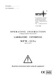
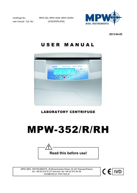
centrifuge No.:user manual - Cat. No.:<strong>MPW</strong>-352, <strong>MPW</strong>-352R, <strong>MPW</strong>-352RH20352/R/RH.ENG2013-04-05U S E R M A N U A LLABORATORY CENTRIFUGE<strong>MPW</strong>-352/R/RHRead this before use!<strong>MPW</strong> <strong>MED</strong>. <strong>INSTRUMENTS</strong>, 46 Boremlowska Street, 04-347 Warsaw/Polandtel. +48 22 610 81 07 (service), fax +48 22 610 55 36mpw@mpw.pl, www.mpw.pl
WARNING SINGS AND HAZARD ICONS.WARNING!Warning of potential injury or health risk.DANGER!Risk of electric shock with potential for severe injury or death as a consequence.DANGER!Biohazard with potential for risk to health or death as a consequence.DANGER!Risk of explosion with potential for severe injury or death as a consequence.This manual was prepared with special care. <strong>MPW</strong> <strong>MED</strong>. <strong>INSTRUMENTS</strong> may change the manual at anytime and without notice because of improvements, typographical errors, inaccuracies of currentinformation or improvements to facilities.2
3Content1 TECHNICAL SPECIFICATION .................................................................................................................... 52 APPLICATION ......................................................................................................................................... 63 INSTALLATION ....................................................................................................................................... 73.1 LOCATION .................................................................................................................................................. 73.2 CURRENT PROTECTION ................................................................................................................................. 84 SAFETY NOTES ....................................................................................................................................... 94.1 OPERATING PERSONNEL ................................................................................................................................ 94.2 GUARANTEE ............................................................................................................................................... 94.3 LOADING THE ROTOR ................................................................................................................................. 104.4 SAFETY HINTS ........................................................................................................................................... 114.5 MAINTENANCE CONDITIONS ........................................................................................................................ 124.6 SAFETY PRECAUTIONS ................................................................................................................................. 125 OPERATING ......................................................................................................................................... 155.1 CENTRIFUGE DESCRIPTION ........................................................................................................................... 155.2 DESIGN ................................................................................................................................................... 165.3 ROTOR AND ACCESSORIES INSTALLATION ........................................................................................................ 165.4 CONTROL DEVICE ...................................................................................................................................... 175.5 SETTING PARAMETERS ................................................................................................................................ 175.6 SAFETY FEATURES ...................................................................................................................................... 176 CENTRIFUGATION ................................................................................................................................ 196.1 CONTROL PANEL ....................................................................................................................................... 196.2 DISPLAY .................................................................................................................................................. 206.3 CENTRIFUGING NOTES ................................................................................................................................ 216.4 SETTING UP RPM, RCF, TIME, TEMPERATURE ............................................................................................... 226.5 USER PROGRAMS ...................................................................................................................................... 246.6 PROGRAMS WITH USER CHARACTERISTICS....................................................................................................... 266.7 CHOOSING ROTORS.................................................................................................................................... 266.8 SHORT MODE ......................................................................................................................................... 276.9 TERMINATING CENTRIFUGATION ................................................................................................................... 277 TEMPERATURE CONTROL .................................................................................................................... 297.1 INITIAL COOLING (R/RH) OR HEATING (RH) WITH CENTRIFUGING ....................................................................... 297.2 INITIAL COOLING (R/RH) OR HEATING (RH) WIHTOUT CENTRIFUGING – THERMAL CHAMBER ............................. 307.3 COOLING (R/RH) OR HEATING (RH) IN “START DELAY – OF TEMPERATURE” MODE ...................................... 307.4 COOLING (R/RH) OR HEATING (RH) IN „SHORT MODE ................................................................................... 307.5 COOLING (R/RH) AND HEATING (RH) NOTES ................................................................................................. 318 PARAMETERS OF CENTRIFUGATION .................................................................................................... 328.1 ACCELERATING/DECELERATING – CHANGING CHARACTERISTICS .......................................................................... 328.2 RADIUS ................................................................................................................................................... 338.3 SAMPLE DENSITY ....................................................................................................................................... 338.4 THERMAL CHAMBER................................................................................................................................... 348.5 AUTOMATIC LID OPENING ........................................................................................................................... 348.6 START DELAY - OF TIME .............................................................................................................................. 348.7 START DELAY – OF TEMPERATURE ................................................................................................................. 358.8 ERRORS ................................................................................................................................................... 368.9 TEMPORARILY DISABLED FUNCTIONS ............................................................................................................. 398.10 UNBALANCE ............................................................................................................................................. 398.11 PRINTING REPORT - USB ............................................................................................................................ 409 CONFIGURATION ................................................................................................................................. 459.1 PASSWORD PROTECTION ............................................................................................................................. 46
9.2 LANGUAGE ............................................................................................................................................... 489.3 MAIN SCREEN MODES ................................................................................................................................ 489.4 TIME/DATE .............................................................................................................................................. 489.5 TOTAL WORKING TIME ................................................................................................................................ 499.6 ROTATING TIME ........................................................................................................................................ 509.7 SOUNDS .................................................................................................................................................. 509.8 ERROR CODES ........................................................................................................................................... 519.9 FACTORY SETTINGS .................................................................................................................................... 519.10 USER CHARACTERISTICS ACCEL/DECEL ........................................................................................................ 529.11 ROTOR RUNTIME ....................................................................................................................................... 569.12 CYCLES HISTORY ........................................................................................................................................ 569.13 MANUFACTURER’S DETAILS ......................................................................................................................... 5610 MAINTENANCE .................................................................................................................................... 5710.1 CLEANING OF THE CENTRIFUGE ..................................................................................................................... 5710.2 MAINTENANCE OF CENTRIFUGE ELEMENTS ...................................................................................................... 5710.3 STERILIZATION .......................................................................................................................................... 5810.4 CHEMICAL RESISTANCE ............................................................................................................................... 6011 TROUBLESHOOTING ............................................................................................................................ 6112 GUARANTEE ........................................................................................................................................ 6313 DISPOSAL ............................................................................................................................................ 6414 MANUFACTURER’S INFO ..................................................................................................................... 6515 ANNEXES ............................................................................................................................................. 67• OPTIONAL ACCESSORIES• STATEMENT OF CONFORMITY• DECLARATION OF DECONTAMINATION - REPAIR• DECLARATION OF DECONTAMINATION - RETURN4
Technical specification1 Technical specificationmanufacturer<strong>MPW</strong> <strong>MED</strong>. <strong>INSTRUMENTS</strong>46 Boremlowska Street, 04-347 Warsaw, Polandtype <strong>MPW</strong> - 352 <strong>MPW</strong> - 352R/RHmains voltage, L1+N+PE, ±10% 230V 115V 230V 115Vmains frequency, ±10% 50/60Hz 50Hz 60Hz 50Hz 60Hzconnected load (max.) 600W 980Wcurrent protection 6,3A 10A 10A 16Acooling medium - R507 (CFC/HCFC free)<strong>MPW</strong> - 352 <strong>MPW</strong> - 352R <strong>MPW</strong> - 352RHcapacity (max.)1000 mlspeed – RPM90 18000 rpm (step 1 rpm)force – RCF 30065 x g (step 1 x g)kinetic energy (max.)19148 Nmrunning time 00:00:01 ÷ 99:59:59 – [hours, min., sec] (step 1s)time countingshort-time operation mode – SHORTcontinuous operation mode – HOLDsince start button is pressed / since preselected speed is reacheduser programms 99 +1*adjustable temperature --20 ÷ 40C**-20 ÷ 55C**(step 1C)(step 1C)initial cooling/heatingPROG 99 (90 ÷ 2500 RPM)no/no yes/no yes/yesguaranteed temperature with max. rotorspeed- ≤4Ccooling/heating without centrifuging no yes/no yes/yescooling/heating with centrifuging no yes/no yes/yesacceleration (ACEL)10 linear curvesdeceleration (DECEL)10 linear curvesprogrammable non-linear curves:acceleration 10deceleration 10USB communicationyesElectromagnetic compatibility according to PN-EN 55011ambient conditionsPN-EN 61010-1 pkt.1.4.1set-up siteindoors onlyambient temperatureyesyes2 ÷ 40Chumidity (maximum relative humidity) < 80%excess-voltage category II PN-EN 61010-1pollution degree 2 PN-EN 61010-1safety areadimensions300 mmheight (H) 380 mm 380 mmwidth (W) 443 mm 443 mmdepth (D) 545 mm 695 mmwith open cover (H oc ) 768 mm 768 mmnoise level 56 dB 56 dBweight 230V 41,8 kg 64,8 kg 65,7 kgweight 115V 45 kg 70,9 kg 71,8 kg* factory program (program no. 99)**time and possibility of obtaining a set temperaturę is dependant on multiple factors , including: rotor type,established RPM, ambient temperaturę; accuracy: - ±1C appropriate for place of temperature sensorMenu languages: POLISH, ENGLISH, SPANISH (without national characters).5
2 ApplicationThe <strong>MPW</strong>-352/R/RH centrifuges are table top laboratory centrifuge for in vitro diagnostic(IVD). Devices are used for separation samples taken from people's, animal’s and plant’s componentsof different densities, under the influence of the centrifugal force, to provide information about theirbiological state (<strong>MPW</strong>-352 – ventilated, <strong>MPW</strong>-352R – with cooling, <strong>MPW</strong>-352RH – with cooling andheating). Its construction ensures easy operation, safe work and wide range of applications atlaboratories engaged in routine medical analyses, biochemical research works etc. This centrifuge isnot biotight and therefore during centrifugation of preparations requiring biotightness one has touse closed and sealed containers and rotors. In the centrifuge, it is prohibited to centrifuge caustic,inflammable and explosive preparations.6
3 InstallationOpen the package. Remove the box containing the accessories. Take out centrifuge from thecontainer. Keep the box and packing materials in case of service shipping.name qty (pcs.) cat no.centrifuge <strong>MPW</strong>-352/R/RH 1 see name platecomplete clamp 1 17664spanner for the rotor 1 17665spanner for emergency opening of the cover 1 17900power cord 230V / 115V 1 17866/17867fuse WTA T 6,3A 250V / WTA T10A 250V / WTAT16A 250V2 17862/17863/17864vaseline 20ml 1 17201USB A-A cable, CD (<strong>MPW</strong> Editor application +FTDI USB drivers)1 16598user manual 1 20352/R/RH/ENG3.1 Location• The centrifuge shall not be located near source of heat and shall notbe subjected to direct sunlight.• The table for the centrifuge shall be stable and shall have flat-levelledtable top.• It is necessary to ensure a safety zone of the minimum 30 cm roundthe centrifuge from every direction.• Normal operating conditions ambient temperature is from 15°C to35°C. Passed parameters of the centrifuge are referring to the abovenamed temperatures.• At the change of the place from cold to warm one, condensation ofwater will occur inside the centrifuge.• It is important then that sufficient time be provided for drying thecentrifuge prior to starting the centrifuge again (min. 4 hours).• Supply voltage given on the rating plate has to be consistent with localsupply voltage. <strong>MPW</strong> Med. instruments laboratory centrifuges are 1stsafety class devices and they are provided with the three-core cablewith the plug resistant to dynamic loadings.• Mains socket shall be provided with the safety pin. It is recommendedto install emergency cut-out that shall be located far from thecentrifuge, near the exit or beyond the room.• Before switching on, check whether the centrifuge is connected topower supply correctly.7
3.2 Current protectionThe centrifuge is equipped with thermal current protection. Fuse is situated inthe plug-in socket unit at back wall of the centrifuge.8
Safety notes4 Safety notes4.1 Operating personnel• Laboratory centrifuge can be operated by laboratory personnel after gettingacquainted with user manual.• User manual shall be always held near the centrifuge.• The centrifuge can not be misused.4.2 Guarantee• Guarantee period amounts to minimum 24 months (unless otherwise specified inthe purchase documents).• The service life of the centrifuge specified by the manufacturer amounts to 10years.• After termination of guarantee period it is necessary to carry out yearly technicalinspections of the centrifuge.• Manufacturer reserves the right to make technical changes in manufacturedproducts.• Maximum period of storage of not used centrifuge amounts to 1 year. After thisperiod, a service authorized by manufacturer should carry out technicalinspection of the centrifuge.9
Safety notesFILLING TUBES• Fill test tubes outside the centrifuge.• Please pay special attention to the quality and proper thickness of the glass testtubes walls. Those shall be test tubes for centrifuges.• Fill test tubes outside the centrifuge.4.4 Safety hintsROTORS MAINTENANCE• Lubricate the swing-out rotor journal pins.• Use only accessories in good condition.• Protect equipment against corrosion using accurate preventive maintenance.HS accessories maintenance• HS accessories maintenance.• Make sure that rubber O-rings are lightly coated with silicone grease. Use highvacuum grease, e.g. type „C” by LUBRINA.HAZARDOUS MATERIALS• Infectious materials could be processed in closed buckets only.• It is not allowed to subject to centrifugation toxic or infectious materials withdamaged leak proof seals of the rotor or test-tube. Proper disinfectionprocedures have to be carried out when dangerous substances contaminatedthe centrifuge or its accessories.EXPLOSIVE AND COMBUSTIBLE MATERIALS• It is not allowed to centrifuge explosive and inflammable materials.• It is not allowed to centrifuge substances prone to reacting in result ofsupplying high energy during centrifugation.Wirówka nie może pracowad wśrodowisku grożącym eksplozją.• It is not allowed to centrifuge materials capable of generating inflammable orexplosive mixtures when subjected to air.11
4.5 Maintenance conditionsSTART-UP• Prior to switching the centrifuge on, one shall read carefully all sections of thisinstruction in order to ensure smooth operation and avoid damages of this deviceor its accessories.• In order to protect the centrifuge against unbalance, fill in the test tubes up to thesame weight.TRANSPORTATION• Centrifuge must not be transported with the rotor mounted on the shaft..GENERAL HINTS• One must use original rotors, test-tubes and spare parts only.• In case of faulty operation of the centrifuge one shall ask for assistance of serviceof <strong>MPW</strong> <strong>MED</strong>. <strong>INSTRUMENTS</strong> company or its authorized representatives.• It is not allowed to switch the centrifuge on if it is not installed properly or rotor isnot fitted correctly.CENTRIFUGES SUBSTANCES• It isn't allowed to exceed load limit set by the manufacturer. Rotors areintended for fluids of average homogeneous density equal to 1,2 g/cm 3 orsmaller when centrifugation is carried out at maximum speed. When fluids ofhigher density shall be used, then it is necessary to change density ofcentrifuges sample in PARAM/DENSITY field.4.6 Safety precautionsFor safety reasons, inspections of the centrifuge carried out by the authorized service at leastonce a year after the period of warranty. The reason for more frequent inspections could becorrosion inducing environment. Examinations should end with issuing report of validation thatchecks on the technical state of the laboratory centrifuge. It is being recommended to establishdocument where every repairs and reviews are being registered. Both these documents should bestored in the place of use of the centrifuge.INSPECTION PROCEDURES CARRIED OUT BY THE OPERATOROperator has to pay special attention to the fact that the centrifuge parts of keyimportance due to safety reasons are not damaged. This remark is specificallyimportant as for:• Motor suspension• Motor axis concentricity• Fixing the pins in the bucket.• Centrifuge accessories and especially structural changes, corrosion, preliminarycracks, abrasion of metal parts.12
• Screw joints.• Inspection of the rotor assembly.• Inspection of bioseals of the buckets if such are used.Safety notes• Control of execution of the guarantee yearly technical inspection of thecentrifugeOnly the manufacturer-specified holders, included in the equipment list, as well ascentrifuge capillaries, which diameter, length and durability are suitable, should beused for spinning in this centrifuge. The use of equipment made by othermanufacturers should be consulted with the manufacturer of the centrifuge.• It is not allowed to lift or shift the centrifuge during operation, and rest on it.• It is nor allowed to stay in the safety zone within 30 cm distance around thecentrifuge neither leave within this zone some things, e.g. glass vessels.• It is not allowed to put any objects on the centrifuge.COVER OPENING• It isn't allowed to open the cover manually in emergency procedure when rotoris still turning.ROTORS• It is not allowed to use the rotors and round carriers with signs of corrosion orother mechanical defects.• It is not allowed to centrifuge highly corrosive substances which may causematerial impairment and lower mechanical properties of rotor and roundcarriers.• It isn’t allowed to use rotors and accessories not admitted by the manufacturer.Let to use commercial glass and plastic test tubes, which are destined tocentrifuging in this laboratory centrifuge. One should absolutely not use poorquality elements. Cracking of glass vessels and test tubes could result indangerous vibration of the centrifuge.• It is not allowed to carry out centrifugation with the rotor caps taken off or notdriven tight.13
5 OperatingNew generation of <strong>MPW</strong> <strong>MED</strong>. <strong>INSTRUMENTS</strong> laboratory centrifuges is provided with state-of-the-artmicroprocessor control systems, very durable and quiet asynchronous brushless motors andaccessories consistent with requirements of the present-day user.5.1 Centrifuge description12435678910111. inspection glass 7. mains socket2. cover 8. clamp3. control panel 9. rotor cover4. emerengcy cover opening 10. rotor5. power switch 11. motor axle6. USB port15
5.2 DesignThe centrifuge has rigid self-supporting structure. Housing was made of sheet aluminium,back made of steel sheet. Front and cover was made of ABS type plastic. Cover is fixed on steel axlesof hinges and from the front it is locked with two electromagnetic locks blocking possible openingduring centrifugation. Rotation chamber casing was made of thick steel sheet. The rotation chamberbowl is made of stainless steel sheet. Rotors and containers are from aluminium, lids frompolycarbonate and reductive inserts from the polypropylene.5.3 Rotor and accessories installation• Connect the centrifuge to the mains (master switch on left side of the centrifuge).• Open the cover of the centrifuge by pressing the COVER key. Prior to putting the rotor in,one has to check if the rotating chamber is free of impurities, e.g. such as dust, glasssplinters, residues of fluids that must be taken away.• One shall fit the rotor on the motor shaft driving it home on the cone.Fitting the rotor too shallow will result in lack of identification of the rotor after start ofthe centrifuge, displaying the error message and stopping the centrifuge.• Screw-in the bolt for fixing the rotor (clockwise) and screw it tightly home with the suppliedspanner for the rotor.• Swing-out rotors have to be provided with the buckets in all seats. One should rememberthat every buckets swings individually. Bucket suspension studs should be lubricatedperiodically with technical petroleum jelly.• In case of rotors designed with the cover they must not be used without it. Rotor coversmust be closed exactly. Rotor covers ensure smaller drags of the rotors, proper setting of thetest-tubes and airtight sealing.• One should use only buckets intended for selected types of the rotor.• Fill test tubes outside the centrifuge.• Put on or screw the caps on vessels and rotors (if applicable).• In case of centrifuging in an angle rotor, test tubes (buckets) have to be filled properly inorder, probówki (pojemniki) muszą byd odpowiednio napełnione w celu uniknięciawylewania.Centrifuge will tolerate small weight differences occurring during loading of rotors.However it is recommended to equalize vessels loads as much as possible in order toensure minimal vibrations during operation. When the centrifuge is started with largeimbalance, the unbalance control system will switch-off the drive system and error signalwill be transmitted. On the monitoring panel, error message will be displayed.• In order to prolong lifetime of the rotor and gaskets rotors shall be lubricated with themaintenance oil, while gaskets and threaded parts shall be lubricated with the technicalpetroleum jelly.16
Operating• For replacement of the rotor one shall unscrew clamping and then grab the rotor with bothhands at opposite sides, taking it away from drive shaft by pulling it up.5.4 Control deviceThe microprocessor control unit of the centrifuge ensures broad possibilities of providing,realisation and reading of work parameters.5.5 Setting parametersData setting and read-out system forms hermetically closed keyboard with distinctlyaccessible operation points. Easily readable displays signaling individual performed operationsfacilitate operator’s programming and recording of parameters and condition of the centrifuge.The centrifuge is provided with the USB interface that enables connection of the centrifuge toexternal PC unit with the printer and recording the centrifugation parameters.5.6 Safety featuresCover lockThe centrifuge can be started only with properly closed cover. While, the cover canbe opened only after stopping the rotor. In case of emergency opening of the cover during operation,the centrifuge will be immediately switched-off and the rotor will brake till complete stopping.Unbalance detectingWhen loads of opposite buckets or carriers in rotors are unbalanced, the drive will beswitched-off during acceleration or operation of the centrifuge – and the error message will bedisplayed.Rotor verification and checking compatibility with loaded progamDirectly after starting centrifuging, a unit verifies the type of the rotor applied and in the caseof its incompatibility with the type indicated in the application or absence of the rotor, the spinningprocess shall be stopped with simultaneous displaying the error message. The conformity of the typeof the rotor is signalled with a single audible signal. Program no. 99 can be run without setting rotor,but the rotor must be supported by the centrifuge.Rest state inspectionOpening of the centrifuge’s cover is possible only with the rotor in the state of rest. Whenthe rotor is being stopped, the STOP diode is on and goes off when it is stopped. (exceptingemergency cover opening) – see p. TROUBLESHOOTING.Checking of excessive temperature <strong>MPW</strong>-352R/RHIf temperature in rotation chamber exceeds 50°C (<strong>MPW</strong>-352) / 65°C (<strong>MPW</strong>-352RH) causedby, for example, malfunction of cooling system, drive will be switched off and error message will bedisplayed. The reboot is only possible after chilling device.17
6 CentrifugationPower switching ON/OFF is carried out with master switch situated on the side wall of the centrifuge.All settings on the centrifuge are done by means of the control panel.6.1 Control panelThe control panel placed on the front casing serves the purpose of controlling centrifugeoperation.Control panel►► SHORT 1 short-time centrifuging► STARTkrótkotrwałestart centrifugation run STOP 2 end centrifugation runCOVERcover openingBACK back buton / cancelling▲ UP navigating in menu / increasing values▼ DOWN navigating in menu / decreasing valuesSET / ● SET changing parameters/ confirming changes◄ LEFTparametrównavigating in menu /► RIGHT navigating in menu /1 the centrifuge is working as long as the key is pressed2 first-time pressing press – will make stopping centrifuging with acceleration characteristics set inthe current program (confirm message with pressing STOP or BACK key), second-time pressing – willmake the centrifuging as fast as possible (quickest characteristic). During setting of the parameters, itserves for exiting zones on the primary screen without introducing changes.19
6.2 DisplayThe display is located in the centre of the control panel. The main screen variants arepresented below.MAIN SCREEN<strong>MPW</strong>-352<strong>MPW</strong>-352R/RHSPEED rotor speed assigned/measuredRCF centrifugal force assigned/measuredTIME centrifuging time assigned/measuredTEMP temperature assigned/measuredPROG ––program no.11199 / ––––rotor no.PARAM –parameters of the centrifugeCONFIGconfiguration menuchanging valuesuser acc/dec curvers(ACC/DEC 10-19)density > 1,2 g/cm 3counting time down (decreasing)cooling to set temperaturecentrifugingrotor stopped / closed coverstopping rotorcounting time up (increasing)heating to set temperaturecentrifuging(with automatic cover opening)rotor stopped / opened lidfastest deceleratingidentyfying rotorthermal chambertemperature delaytime delayzone mark of assigning of thecentrifuging timedrop-down list20
Centrifugationtemporairly disabledlockedtime counting (blinking)disabled option / drop-down listdisabled optionactive option / drop-down listactive option6.3 Centrifuging notes• Connect the centrifuge to the mains (master switch on left side of the centrifuge).• Open the cover of the centrifuge by pressing the COVER key. Prior to putting the rotor in,one has to check if the rotating chamber is free of impurities, e.g. such as dust, glasssplinters, residues of fluids that must be taken away.• One shall fit the rotor on the motor shaft driving it home on the cone.Fitting the rotor too shallow will result in lack of identification of the rotor after start ofthe centrifuge, displaying the error message and stopping the centrifuge.• Screw-in the bolt for fixing the rotor (clockwise) and screw it tightly home with the suppliedspanner for the rotor.• Swing-out rotors have to be provided with the buckets in all seats. One should rememberthat every buckets swings individually. Bucket suspension studs should be lubricatedperiodically with technical petroleum jelly.• In case of rotors designed with the cover they must not be used without it. Rotor coversmust be closed exactly. Rotor covers ensure smaller drags of the rotors, proper setting of thetest-tubes and airtight sealing.• One should use only buckets intended for selected types of the rotor.• Fill test tubes outside the centrifuge.• Put on or screw the caps on vessels and rotors (if applicable).• In case of centrifuging in an angle rotor, test tubes (buckets) have to be filled properly inorder to avoid overflows.Centrifuge will tolerate small weight differences occurring during loading of rotors.However it is recommended to equalize vessels loads as much as possible in order toensure minimal vibrations during operation. When the centrifuge is started with largeimbalance, the unbalance control system will switch-off the drive system and error signalwill be transmitted. On the monitoring panel, error message will be displayed.• In order to prolong lifetime of the rotor and gaskets rotors shall be lubricated with themaintenance oil, while gaskets and threaded parts shall be lubricated with the technicalpetroleum jelly.• For replacement of the rotor one shall unscrew clamping and then grab the rotor with bothhands at opposite sides, taking it away from drive shaft by pulling it up.21
6.4 Setting up RPM, RCF, TIME, temperatureOn the main screen, it is possible to set:rotating speedrelative centrifugal forcecentrifuging timecentrifuging temperatureSPEED (RPM)RCFTIMETEMP (R/RH only)Exemplary change of SPEED setting:• Press SET (to enter edit mode).• With ▲▼◄► keys mark SPEED fold(blinking).When RPM is changed, RCF is automatically corrected.• Press SET.• Choose demanded order of magnitudeby pressing ◄►, e.g.: Xxxx (X - blinking).• Set demanded value by pressing ▲▼.• Repeat above two steps for other ordersof magnitude.• Confirm set value by pressing SET.• Leave edit mode by pressing BACK.Exemplary change of RCF setting:• Press SET (to enter edit mode).• With ▲▼◄► keys mark RCF fold(blinking).When RCF is changed, RPM is automatically corrected.• Press SET.• Choose demanded order of magnitudeby pressing ◄►, e.g.: Xxx (X - blinking).• Set demanded value by pressing ▲▼.• Repeat above two steps for other ordersof magnitude.• Confirm set value by pressing SET.• Leave edit mode by pressing BACK.22
CentrifugationExemplary change of TIME setting:• Press SET (to enter edit mode).• With ▲▼◄► keys mark TIME fold(blinking).• Press SET.• Choose demanded order of magnitudeby pressing ◄►, e.g.: Xx:xx:xx (X -blinking).• Set demanded value by pressing ▲▼.• Repeat above two steps for other ordersof magnitude.• Confirm set value by pressing SET.• Leave edit mode by pressing BACK.Exemplary change of TEMP setting:• Press SET (to enter edit mode).• With ▲▼◄► keys mark TEMP fold(blinking).• Press SET.• Set demanded value by pressing ▲▼.• Confirm set value by pressing SET.• Leave edit mode by pressing BACK.Changing parameters during runThere is a possibility to change parameters:SPEED, RCF, TIME, TEMP during centrifuging.Such modifications give in currently runningprogram. Modification during run is representedby PROG –– symbol.Detailed description of setting values (e.g. TIME).23
• Press SET (to enter edit mode).• With ▲▼◄► keys mark TIME fold(blinking).0 0 : 0 7 : 0 0hh : mm : sse.g.:• centrifuging time – 4 minutes 19 seconds• Press SET.• Choose “hours”, “minutes” or “seconds”by pressing ◄►, e.g.: XX:xx:xx (XX -blinking).• Set demanded value by pressing ▲▼.• Repeat above two steps to set demandedtime.• Confirm set value by pressing SET.• Leave edit mode by pressing BACK.set valuecurrent calue (most significant digits)– – – –– – – – symbol shows which orders ofmagnitude are currently shown incurrent value foldHOLD modecontinuous operation mode• To run centrifuging in HOLD mode set00:00:00 time.• To end centrifuging in HOLD mode pressSTOP.6.5 User programsAfter switching centrifuge on, program thatwas used in previous session is being loaded.Modification during run is represented byPROG –– symbol.24
CentrifugationChoosing program:FAST MODE:• Press SET.• With ▲▼◄► keys mark PROG –– fold(blinking).Wcisnąd klawisz SET.• Set demanded program by pressing ▲▼.• Confirm by pressing SET.• Press SET.LIST:• With ▲▼◄► keys mark PROG ––zone.• Press SET.• With ▲▼ keys choose demandedprogram number. (marked by ).• Confirm by pressing SET.• With ▲▼ keys choose choose one of fourpossibilities: LOAD, SAVE, DELETE, NEW:– currently loaded program.• LOAD – load program,• ZAPIS – save settings as a program(confirm by selecting YES and pressingSET)• DELETE – delete program (confirm byselecting YES and pressing SET)NEW – load default parameters:• TEMPERATURE: +20°C,• SPEED: 2000 RPM,25
Centrifugation6.8 SHORT modeSHORT mode• In SHORT mode the centrifuge is working as long as the ►► (SHORT) key ispressed or when set time is over.6.9 Terminating centrifugationSTOPPING CENTRIFUGATION CYCLE• When preselected time is reched, centrifugation will end automatically.x1x2• Pressing STOP for the first time will stop centrifuging with the charasteristicset in loaded program. Confirm message by pressing STOP lub SET.• Pressing STOP second time will stop centrifuging with the fastestcharacteristic.27
7 Temperature control<strong>MPW</strong>-352R/RH onlyCentrifuge is equipped in ecological refrigerating system with temperature control. Duringcentrifugation, there may appear differences in temperature on the display and temperature of thesamples in the rotor. It depends on thermal conductivity of the rotor, and samples and centrifugationtime.Exemplary change of TEMP setting:• Press SET (to enter edit mode).• With ▲▼◄► keys mark TEMP fold(blinking). Press SET.• Set demanded value by pressing ▲▼.• Confirm set value by pressing SET.• Leave edit mode by pressing BACK.• When chamber is being cooled orheated, symbol is visible on thescreen (blinking).7.1 Initial cooling (R/RH) or heating (RH) with centrifuging90 2500RPM• In order to centrifuge preparations of a lowered temperature (deposited inthe outside refrigerator) it is necessary to make initial refrigerating of thechamber, the rotor and containers, to the set low temperature, in order tominimise the difference of temperatures• Initial cooling/heating function can be activated by executing PROGRAM99.Parameters:• TEMPERATURE,• SPEED: 90 2500 RPM,• TIME.Initial cooling/heating functions can be terminated anytime by pressingSTOP key.29
When cooling/heating function is active,/ symbol is visible on the screen(blinking).When Initial cooling or heatling is active,PROG 99 and arrows / are visible(blinking) in TEMP fold.7.2 Initial cooling (R/RH) or heating (RH) wihtout centrifuging – THERMALCHAMBERCONFIG THERMAL CHAMBER0 RPM• There is possible to run centrifuge in THERMAL CHAMBER mode - coolingfor R, cooling and heating for RH (rotor is at standstill).• How to enable THERMAL CHAMBER is described in Parameters ofcentrifugation chapter.7.3 Cooling (R/RH) or heating (RH) in “START DELAY – OF TEMPERATURE” modeCONFIG START DELAY – OF TEMPERATURE2500 RPM• Centrifuging process will start, when preselected temperature is reached.• How to enable run START DELAY – OF TEMPERATURE function is describedin Parameters of centrifugation chapter.7.4 Cooling (R/RH) or heating (RH) in „SHORT mode• Cooling and heating features are avalaible in SHORT mode.• How to enable run centrifugation in SHORT mode is described inCentrifugation/SHORT mode.30
Temperature control7.5 Cooling (R/RH) and heating (RH) notesCentrifuges with cooling (R) or cooling and heating (RH) are equipped with an efficientcooling system. It allows obtaining selected temperatures in the chamber even at maximum spinspeed or fast obtaining desired temperatures (e.g. 4:C and 36:C). Note that time and possibility ofobtaining a set temperature is dependent on multiple factors, including: the power of the coolingsystem, the shape of the rotor, the rotor speed, ambient temperature, etc. The accuracy of thetemperature stability of ± 1 : C is determined by the installation place of the temperature sensor.31
8 Parameters of centrifugation• Press SET.• With ▲▼◄► keys select PARAM. PressSET (to enter PARAM menu).ACCELERATIONDECELERATIONRADIUS [MM]DENSI (g/cm 3 )THER. CHAMB.OPEN LID AFTER RUNSTART DELAYchosen acc. characteristicchosen dec. characteristiccurrent rotor radiussample densitycooling / cooling and heating of the chamberopening cover after centrifuging automatilcallystarting delayed (after pressing START)8.1 Accelerating/decelerating – changing characteristics• ACCELERATION – 10 linear acceleratingcharacteristics assigned to every rotor (0÷ 9),• DECELERATION – 10 linear deceleratingcharacteristics assigned to every rotor (0÷ 9).32
Parameters of centrifugation8.2 Radius• RADIUS [mm] - control of the radius ofthe rotor within the range from R min toR max . Avalaible values depends on chosenrotor, see ––––– / ––––– (LIST OFROTORS fold).• When radius is changed is activated,symbol is visible on the screen.• Reducing of the rotor radius (and theresulting change of displayed RCF value)applies until switching off the powersupply of the centrifuge or setting theRmax maximum radius once again(loading the program does not changethis setting!).• To change the rotor radius selectRADIUS [mm] with ▲▼◄► keys.[MM]. Press SET. Set demanded value bypressing ▲▼. Press SET to acceptchanges.8.3 Sample density• DENSI (g/cm 3 )) – default density is set to1,2 g/cm 3 (possible values 1,2 ÷ 9,9g/cm 3 ).• When density is changed, symbol isvisible on the screen.• Increasing density of the sample above1,2 g/cm 3 (and limiting of the maximumspeed of centrifuging resulting from it)applies until switching off power supplyof the centrifuge or setting the deviceback to 1,2 g/cm 3 .• To change the density select DENSI(g/cm 3 )) with ▲▼◄► keys. [MM].Press SET. Set demanded value bypressing ▲▼. Press SET to acceptchanges.33
8.4 Thermal chamber<strong>MPW</strong>-352R/RH onlyTHERMAL CHAMBER• With ▲▼◄► keys select THERMALCHAMBER. Press SET (to turn on/off).• Set demanded value by pressing ▲▼.• When THERMAL CHAMBER function isactivated, symbol is visible on thescreen.• Changing temperature from the mainscreen is not possible.• Opening cover terminates THERMALCHAMBER function (closing cover backturns it on).• If THERMAL CHAMBER is turned on (in PARAM fold) and centrifugation completes, THERMALCHAMBER will activate itself.• THEMRAL CHAMBER can be only activated when any other program is not running.8.5 Automatic lid openingAutomatic lid openingOPEN LID AFTER RUN• When centrifuge process is finished,cover will be opened automatically.• When centrifuging is terminated bypressing STOP, opening cover is possibleby pressing COVER.• symbol means that OPEN LID AFTERRUN is active.8.6 Start delay - of timeStart centrifuging sincepreselected delay is reached.STARY DELAY / OF TIME34
Parameters of centrifugation• With ▲▼ keys select START DELAY.Press SET.• Start delay can be set from0 : 0 0 : 0 1 to 9 : 5 9 : 5 9.• With ▲▼ keys select OF TIME. PressSET.• Press ▼, then ► select time zone (e.g.0 : 0 0 : 4 2).• With ▲▼ keys set demanded value.• Confirm by pressing SET.• When START DELAY function is activated,symbol is visible on the screen.symbol informs that time is remaining.START DELAY / OF TIME function cannot be run when START DELAY / OF TEMP. is activated.8.7 Start delay – of temperature<strong>MPW</strong>-352R/RH only2500 RPMStart centrifuging since preselectedtemperature is reached.START DELAY / OF TEMP.• With ▲▼ keys select START DELAY.Press SET.• With ▲▼ keys select OF TEMP. PressSET.• With ◄► keys select temperature zone.• With ▲▼ keys set demanded value.• When START DELAY – OF TEMPERATUREis turned on, symbol is visible on thescreen. / (blinking) symbolsmeans that temperature is increasing /decreasing.When function is active, rotor is rotating with 2500rpm or lower (in order of fasttemperature reaching).START DELAY / OF TEMP. function cannot be run when START DELAY / OF TIME is activated.35
8.8 ErrorsEnd of centrifuging – manual modeCentrifuging may be stopped at the any momentwith the STOP key. The information message willbe displayed.End of centrifuging – normal modeStopping centrifuging in accordance with the settime causes generating 3 short audible signals(after stopping the rotor) and displaying themessage.Additional messagesIn case of power shortage while centrifuging,after repeated switching it on, the followingerror screen will be displayed.After operating for 2000 hours, after everyswitching on the centrifuge the error screen isbeing displayed with information about thenecessity to carry out servicing activities.After pressing the SET key, the device proceedsto the main screen and the device may operate.Identified number of the installed rotor. If therotor is unknown the "--?--" sign is beingdisplayed.Decelarating.After pressing SET or STOP, the device returns to the main screen.36
Parameters of centrifugationOther messagesAn irregularity in operations of the centrifuge issignalled by displaying a screen with relevantmessage (a sound signal is also emitted).'===============================================================================SPEED OF ROTOR IDENTIFICATION 90 RPM'==============================================================================="SPEED OF ROTOR ""IDENTIFICATION 90 RPM"'===============================================================================UNBALANCE DETECTED'==============================================================================="IMBALANCE FAST STOP !""PLEASE REMOVE CAUSE""THEN RESTART"'===============================================================================ERROR OF ROTOR IDENTIFICATION {LIMIT OF 6SEC. IS OVER}'==============================================================================="NO ROTOR OR IDENTIFICATION""SENSOR DAMAGED !"'===============================================================================ROTOR’S IDNOT CORRECT'==============================================================================="INCORRECT ROTOR NUMBER !"'===============================================================================WRONG DIRECTION OF ROTATION / UNKNOWN ROTOR'==============================================================================="WRONG DIRECTION OF ROTATION""OR UNKNOWN ROTOR !"'===============================================================================CLOSING THE LID MANUALLY'==============================================================================="PLEASE CLOSE THE LID""HAND !"'===============================================================================INITIALIZING AFTER MAINS FAILURE WITH ROTATING ROTOR'==============================================================================="ROTOR STOPPING !""Please wait..."'===============================================================================CENTRIFUGING ENDED BECAUSE OF PRESSING STOP'===============================================================================" CYCLE'S ABORTED !"'===============================================================================CENTRIFUGING ENDED {WITROUT ERRORS}'===============================================================================" CYCLE'S FINISHED"37
Emergency messagesIn case of emergency messages (centrifuge is notwoking properly) contact the manufacturer'sauthorized service center.===============================================================================INVERTET ERROR, INVERTER NOT READY {BETRIEBSBEREIT=1}'==============================================================================="OVERHEATING MOTOR !""INVERTER ERROR !""ERROR=" ; Kod_bledu'===============================================================================COMMUNICATION ERROR CONTROLLER - INVERTER {BLOK 1}'==============================================================================="INVERTER SERIAL BUS ERROR !""ERROR=" ; Kod_bledu'===============================================================================TEMP. METER ERROR: DS18B20'==============================================================================="TEMPERATURE SENSOR ERROR""ERROR=" ; Kod_bledu'===============================================================================PRESSURE REGULATOR ERROR'==============================================================================="PRESSURE CONTROL FAILURE!"'===============================================================================COVER OPENED DURING RUN'==============================================================================="OPENING COVER in RUN!"'===============================================================================SPEED METER ERROR {NO IMPULSES }'==============================================================================="SPEED METER ERROR"'===============================================================================SEQUENCE OF 3 I2C TRANSMISSIONS FAULT;'==============================================================================="I2C BUS ERROR""ERROR=" ; Kod_bledu'===============================================================================CENTRIFUGE OVERHEATED; CENTRIFUGE TEMPERATURE >= +50/+65 oC'==============================================================================="OVERHEATING CENTRIFUGE !""Temp.= +" ; _temp_przegrzania_off ; " oC"'==============================================================================='V>VOGR_ROTOR ; ROTOR OVERSPEED {VOGR_ROTOR=VMAX_ROTOR+DELTA_VMAX}'==============================================================================="ROTOR OVERSPEED !"===============================================================================COVER LOCK FAILURE'==============================================================================="COVER LOCK MALFUNCTION !"'===============================================================================SERVICE NEEDED; TIME {2000 HOURS}'==============================================================================="WORKING 2000 HOURS:""CALL SERVICE FOR"38
Parameters of centrifugation8.9 Temporarily disabled functionsFunctions written below can be temporarily disabled.SPEED RCF TIME TEMP PROG –– ––––– / ––––– PARAMTHERMALCHAMBER● ● ● ○ ● ● ●During runSPEED RCF TIME TEMP PROG –– ––––– / ––––– PARAMPROG 99 ○ ○ ○ ○ ○ ○ ○ACC/DEC10-19○ ○ ● ● ○ ○ ●StandstillSPEED RCF TIME TEMP PROG –– ––––– / ––––– PARAMPROG 99 ○ ○ ○ ○ ● ○ ○ACC/DEC10-19○ ○ ● ● ● ○ ●● available○ disabled8.10 UnbalanceThe centrifuge is provided with the rotor unbalance sensor and when it will be activated,centrifugation process will be stopped through fast braking and at the same time an error messagewill be displayed. Cancellation of this error is possible only through pressing COVER key afterstopping of the rotor.One must check if rotor was correctly loaded, close the cover and once more start theprogram. In order to protect the rotor against beating in opposite areas of the rotor, it has to beprovided with identically filled buckets, carriers, test-tubes etc. for getting the best balance possible.Unbalance causes noise and vibrations during operation, and adversely affects powertransmission system (motor, shock absorbers). The better balance, the smoother willbe the centrifuge operation and therefore longer life of usage of the driveline.Moreover, the ideal separation level is then obtained, as already separatedconstituents would not be moved up by vibration.39
Emergency stopIn any moment of centrifuging it is possible interrupt the process and fast stop the rotor.Single-time pressing of the STOP key will make centrifuging stop with acceleration characteristics setin the program (after pressing the SET or STOP key, the device returns to the main screen). Pressingand holding it up to 1s will make the centrifuging stop with the most strict characteristic.8.11 Printing report - USBWhen the centrifuging process is finished there is a possibility to obtain report. Report can betransferred to PC or printed. Devices that offer printing reports are available optionally and they arenot delivered with every centrifuge.PC (USB)namequantity(pcs.)USB A-A cable 1CD (<strong>MPW</strong> Editor application + FTDI USB drivers) 1cat. no.16598USBPreparation• Connect centrifuge to the PC with the USB A-A cable (connection diagram isgiven below).• if necessary install FTDI USB drivers (for details see attached CD).• Ensure that virtual serial port COM (USB Serial Port) settings are set as describedbelow (run control panel/system/ device manager):• Baud rate = 9600• Data length = 8• Parity = none• Stop bite = 1• Flow control = none40
Parameters of centrifugation• Install <strong>MPW</strong> Editor application (Windows) delivered on CD.Centrifuging and printing report• Run <strong>MPW</strong> Editor application.• Choose Język\English• Choose COM port assigned to the centrifuge (it will appear after connecting USBcable, e.g. COM11).• Choose File\Edit form• Fill individual folds (optionally).• In the folds with explerary caption „Tytuł (Title)”, there is a possibility to paste formsystem clipboard any picture (e.g. company logo).41
• Choose File\Save form• Choose Open42
Parameters of centrifugationConnection diagram• Start centrifuging.• When centrifuging process is completed, report will appear. Save report (File/Saveus or print it (File/Print).• In order to get another report, press New test.CENTRIFUGE (left-bottom corner)▼43
►►USB cablePCUSB port44
Configuration9 Configuration• Press SET.• With ▲▼◄► keys select CONFIGmenu. Press SET.• To navigate in CONFIG use ▲▼◄►keys. To enter CONFIG menu press SET.CODELANGUAGESCREENTIME/DATECYCLESROTATING TIMEBUZZERSENSORRESETCURVESROT. RUNTIME10-CYCLESCONTACT USpassword protectionmenu languagemain screen modestime and date settingstotal working time, working cycles countercounting time modesystem soundserror codesrestore factory settingsuser characteristics (ACC, DEC)total running time10 last centrifugation cycles historymanufacturer’s details45
9.1 Password protectionSetting up passwordCONFIG / PASSWORDTo prevent from an unauthorized use, a PASSWORD can be set.Note: No PASSWORD is set by default.The PASSWORD can be set as follows when the rotor is at a standstill.• Press the ◄► keys until “PASSWORD:”blinks. Press SET.• With ◄► keys set the valid 1000s placeof the PASSWORD. e.g.: 1xxx. With ▲▼keys set correct value.• Repeat above steps for all places.• Press SET.• As a confirmation repeat instructionsdescribed above.When the PASSWORD is set, the Key sign is displayed in the CODE zone. It is also displayed in themain menu (lower right corner of the screen).From this moment CONFIG menu is protected.To delete the PASSWORD, “0000” must be set.If the PASSWORD is forgotten, the emergency code “7654” should be used to clear password andremove all locks.46
ConfigurationSetting up locks• With ▲▼ keys choose a lock.• Mark a lock by pressing SET.• Repeat above steps for desired locks.• Leave menu with BACK key.SAVE PROGRAMDELETE PROGRAMCHANGE PARAMETERSDISABLEDSAVE buttonDELETE buttonSPEEDRCFTIMETEMPPROG––––––– / –––––PARACURVESdescription• no programs can be saved• acceleration charactristics cannot be saved• deceleration charactristics can notbe saved• no programs can be deleted• saving programs on positionwhere one was already stored isdisabled• parameters can not be modifiedLOAD PROGRAM LOAD button • no programs can be called upSTART KEYkey• centrifugation can not be started* Executing disabled procedures is only possible after entering the correct47
9.2 LanguageChoosing menu language.CONFIG / LANGUAGE• With ▲▼ keys select demanded option.• Mark selection by pressing SET.9.3 Main screen modesChoosing main screen mode.CONFIG / SCREEN• With ▲▼ keys select demanded option.• Mark selection by pressing SET.<strong>MPW</strong>-352<strong>MPW</strong>-352R/RHSPEED and RCFSPEED onlyRCF only9.4 Time/dateSetting the time and date.CONFIG / TIME/DATE48
Configuration• With ▲▼ keys select demanded option.• Mark selection by pressing SET.• With ▲▼ keys select DATE TIME (blinking).Press SET.• With ◄► keys place _ _ underdemanded value. Press SET.• With ▲▼ keys change selected value.Accept changes by pressing SET.• Repeat above steps for other values.• Choose EXIT.9.5 Total working timeTotal working time of centrifugeCONFIG / CYCLESIn the CYCLES menu the following statistics aredisplayed:• total working (centrifugation) time• working cycles counterWhen the total working time is greater than2000h, the warning splash screen will bedisplayed every time the centrifuge is switchedon. In case the centrifuge should be examined bythe manufacturer’s service.Warning message can be disabled. In order to itfollow the instructions below:• With ▲▼ keys chooseWARNING: WORKING 2000 HOURS.• Press SET until ⧈ disappears.• Choose EXIT.The CYCLE WARNING MESSAGE is turned on bydefault.49
9.6 Rotating timeCounting time modeCONFIG / ROTATING TIME• With ▲▼ keys select demanded option.• Mark selection by pressing SET.Counting since:• START key is pressed COUNTING SINCE ROTOR IS IDENTIFIED• preselected speed is reached COUNTING FROM ASSIGNED SPEEDPresenting mode:• remaining time COUNTING DOWN• left time COUNTING UP9.7 SoundsSwitching ON/OFF short audible signalsaccompanying every pressing of any key.CONFIG / SOUNDS• With ▲▼ keys select demanded option.• Mark selection by pressing SET.Warning signals connected with error occurrence, cannot be switched off.50
Configuration9.8 Error codesInformation about errors arisen in working of thecentrifuge.CONFIG / SENSORIntended for service purposes!• In any moment, it is possible to deletethe contents of the fold.• For this purpose, choose DELETE button(blinking when marked) and confirm bypressing SET key.9.9 Factory settingsRestoring factory setings.CONFIG / RESETAll menu settings will be restored to ita original values.• With ▲▼ keys select YES or NO.• Confirm by pressing SET.51
9.10 User characteristics ACCEL/DECELUser acceleration/decelerationcharacteristicsCONFIG / CURVES• Choose the program by pressing ▲▼ keys.Press SET.• To edit acceleration characteristic chooseACCEL (by pressing ◄►). Confirm selection bypressing SET.Acceleration characteristicCONFIG / CURVES / ACCELAfter choosing CONFIG CURVES ACEL the window of the characteristics wizard will be displayed:Current acceleration characteristic connected with the loaded program will be displayed on the screen.NO. section no. (max. 4)TIMESPEEDtotal acceleration timefinal RPMACC:11 characteristic’s no. (10-19)In the first moment, the EXIT field is marked (the message is blinking). Pressing the SET key will causereturning to the CONFIG / CURVES fold, without making changes in the acceleration characteristics.„1” SECTIONAfter setting the time the device will proceed to setting the speed of the given section ofcharacteristics (only the set value SPEED blinks). With UP and DOWN keys one should set the speedvalue and press the SET key.The set speed value is limited by the maximum speed of the rotor connected with the editedprogram. After the end of programming the speed, the graphical displaying of the section (of allsections) will occur TIME+SPEED of the user's acceleration characteristics.After programming the section 1, there is a possibility to program the next section, number 2:52
Configuration„2” SECTIONProgramming of new section possible (the wholeline 2 is blinking). Programming as in the case ofsection 1. It is possible also to abandon theprogramming: with UP/DOWN keys choose theEXIT option (it will blink) and save (press the SET)only the acceleration characteristics of 1 sectionwith TIME/SPEED parameters described in theline 1.The minimal speed of the next section of acceleration characteristics is equal to the speed of thealready programmed previous section.„3” SECTIONProgramming of new section possible (the wholeline 3 is blinking). Programming as in the case ofsection 1. It is possible also to abandon theprogramming: with UP/DOWN keys choose theEXIT option (it will blink) and save (press the SET)only the acceleration characteristics of 2 sectionwith TIME/SPEED parameters described in theline 1 and 2.„4” SECTIONProgramming of new section possible (the wholeline 4 is blinking). Programming as in the case ofsection 1. It is possible also to abandon theprogramming: with UP/DOWN keys choose theEXIT option (it will blink) and save (press the SET)only the acceleration characteristics of 3 sectionwith TIME/SPEED parameters described in theline 1, 2 and 3.Repeated attempt to program already programmed sections of the acceleration characteristics willcause beginning of programming of the whole acceleration characteristics once again (with settingsof the program loaded to edition.53
Deceleration characteristicCONFIG / CURVES / DECELAfter choosing CONFIG CURVES DECEL the window of the characteristics wizard will be displayed:Default deceleration characteristics connected with the loaded program will be displayed on thescreen. Creating of deceleration characteristics takes place a little differently than accelerationcharacteristics.NO. section no. (max. 4)TIMESPEEDtotal acceleration timefinal RPMDEC:11 characteristic’s no. (10-19)In the first moment, the EXIT field is marked (the message is blinking). Pressing the SET key will causereturning to the CONFIG / CURVES fold, without making changes in the deceleration characteristics.„1” SECTIONTo edit the deceleration characteristics, one should mark the section of characteristics with UP orDOWN key (the whole TIME+SPEED line will begin to blink; at this stage, it is only one section, withthe number 1) and then press the SET key. The device will proceed to setting the characteristics'section time (only the set TIME value is blinking). With UP and DOWN keys, one should set therequired time value and press the SET key.In order to compete the creation of the deceleration curve it is necessary for the speed of the lastof programmed sections of the curve to be equal = 0. Otherwise the curves wizard will not enablethe end of programming (it will be impossible to select the EXIT option).After programming the section 1, there is a possibility to program the next section, number 2:„2” SECTIONNew section programming possible (the wholeline 2 is blinking). Programming as in the case ofthe section 1. To stop creating the decelerationcurve at the stage of two sections, it is necessaryto set the speed in section 2 to 0 and press theSET key.The maximum speed of the next section of deceleration characteristic is equal to the speedprogrammed already of the previous section.54
Configuration„3” SECTIONNew section programming possible (the wholeline 3 is blinking). Programming as in the case ofthe section 1. To stop creating the decelerationcurve at the stage of three sections, it isnecessary to set the speed in section 3 to 0 andpress the SET key.„4” SECTIONNew section programming possible (the wholeline 4 is blinking). Programming as in the case ofthe section 1. If speed of the last section=0, it ispossible to save the created characteristics bychoosing the EXIT option with UP/DOWN keysand pressing the SET key.Repeated attempt to program already programmed sections of the acceleration characteristics willcause beginning of programming of the whole deceleration characteristics once again (withsettings of the program loaded to edition).In case of continuing work with currently loadedprogram with new user characteristics, usershould choose YES (to load new characteristics).55
9.11 Rotor runtimeInformation about the time of centrifugingand of the quantity of the working cycles ofeach rotor. The table also contains iconswarning of the duty of execution ofvalidation.CONFIG / ROT. RUNTIME• The list can be scrolled using ▲▼ keys.• To exit press SET/BACK key.– more than 100 cycles left– less than 100 cycles left– worn rotor9.12 Cycles historyInformation concerning parameters of tenlast centrifuging cycles.CONFIG / 10-CYCLES• Number od cycle can be changed by ◄►keys.• The list can be scrolled using ▲▼ keys.• To exit press SET/BACK key.9.13 Manufacturer’s detailsInformation about the type of the centrifuge,firmware version, and contact details.CONFIG / CONTACT US• The list can be scrolled using ▲▼ keys.• To exit press SET/BACK key.56
Maintenance10 Maintenance10.1 Cleaning of the centrifuge• For cleaning, water with soap or other water soluble mild detergent shall beused. One should avoid corrosive and aggressive substances.• It is prohibited to use alkaline solutions, inflammable solvents or agentscontaining abrasive particles.• Using wiping cloth, remove condensate or residues of the products from therotor chamber. It is recommended to keep the cover opened when thecentrifuge does not work in order to expel the moisture.• In case the user decides to use centrifuge and equipment cleaning methodsother than the ones described in this manual, the user shall contact thedevice manufacturer in order to check whether the cleaning method chosendoes not damage the device.10.2 Maintenance of centrifuge elements• The rotor pins shall be always lubricated with technical petroleum jelly.• In this way, the uniform deflection of the buckets and quiet centrifugeoperation is ensured.Cleaning of the accessories• In order to ensure safe operation one shall carry out in regular way periodicalmaintenance of the accessories.• Rotors, buckets and round carriers have to withstand steady high stressesoriginating from the field of gravitation. Chemical reactions as well ascorrosion (combination of variable pressure and chemical reactions) cancause corrosion or destruction of metals. Hard to observe surface cracksincrease gradually and weaken material without visible symptoms.• In case of observation of surface damage, crevice or other change, as well asthe corrosion, the given part (rotor, bucket, etc.) shall be immediatelyreplaced.• In order to prevent corrosion one has to clean regularly the rotor with thefastening bolt, buckets and round carriers.• Cleaning of the accessories shall be carried out outside of the centrifuge onceevery week or still better after each use.• Then, those parts shall be dried using soft fabric or in the chamber drier at ca.57
50°C.• Especially prone to the corrosion are parts made of aluminium. For cleaningthem one should use neutral agent of pH value 6÷8.• It is forbidden to use alkaline agent of pH > 8.• In this way, the useful service life of the device is substantially increased andsusceptibility to corrosion is diminished.• Accurate maintenance increases the service life as well and protects againstpremature rotor failures.• Corrosion and damages resulting from insufficient maintenance could not besubject of claims lodged against the manufacturer.Lubrication• The rotor pins shall be always lubricated with technical petroleum jelly.• In this way, the uniform deflection of the buckets and quiet centrifugeoperation is ensured.• HS accessories maintenance.• Make sure that rubber O-rings are lightly coated with silicone grease. Usehigh vacuum grease, e.g. type „C” by LUBRINA.10.3 SterilizationOne can use all standard disinfectants. The centrifuges and accessories are constructed fromvarious materials and one should to take into account possible variety of materials. Duringsterilization by means of steam one should to consider temperature resistance of individualmaterials.STERILIZATIONsterilization *radiation βradiation γC 2 H 4 O(ethylene oxide)formalin,ethanol121 ° C,20 min25 kGyPS ○ ● ○ ●SAN ○ ○ ● ●PMMA ○ ● ○ ●PC ● 1) ● ● ●PVC ○ 2) ○ ● ●POM ● 1) ● ● ●PE-LD ○ ● ● ●PE-HD ○ ● ● ●PP ● ● ● ●PMP ● ● ● ●ECTFE● ○ ● ●ETFEPTFE ● ○ ● ●FEP/PFA ● ○ ● ●58
aldehydescyclic alcoholsestersetherketonesstrong orconcentrated acidsweak or dilutedacidsoxidizingsubstancescyclichydrocarbonsahshaloidhydrocarbonsalkalisFKM ● ○ ● ●EPDM ● ○ ● ●NR ○ ○ ● ●SI ● ○ ● ●●○*may be usedcannot be usedMaintenanceLaboratory vessels have to be exactly cleaned and rinsed with the distilled water before the sterilization in theautoclave. It is always necessary to remove closures from containers!1) The frequent steam sterilization reduces mechanical durability! PC test tubes may become useless.2) Except PVC hoses which are resistant to the steam sterilization in the temperature 121°CChemical resistance of plasticsPS ○ ● ○ ○ ○ ○/● ○/● ○ ○ ○ ○ ●SAN ○ ● ○ ○ ○ ○ ○/● ○ ○ ○ ○ ●PMMA ○/● ● ○ ○ ○ ○ ○/● ○ ○/● ○ ○ ○PC ○/● ● ○ ○ ○ ○ ○/● ○ ○/● ○ ○ ○PVC ○ ● ○ ○ ○ ● ● ○ ● ○ ○ ●POM ○/● ● ○ ● ● ○ ○ ○ ● ● ● ●PE-LD ● ● ● ○/● ● ● ○ ● ● ● ●PE-HD ● ● ○/● ○/● ○/● ● ● ○ ● ○/● ○/● ●PP ● ● ○/● ○/● ○/● ● ● ○ ● ○/● ○/● ●PMP ○/● ● ○/● ○/● ● ● ○ ○/● ○ ○ ●●●● ● ○ ● ● ● ● ● ● ●ECTFEETFEPTFEFEPPFA●●● ● ● ● ● ● ● ● ● ●FKM ● ○ ○ ○ ○ ○ ● ○/● ○/● ○/● ○/● ○/●EPDM ● ● ○/● ○ ○/● ● ● ○/● ○ ○ ○ ●NR ○/● ● ○/● ○ ○ ○ ○/● ○ ○ ○ ○ ●SI ○/● ● ○/● ○ ○ ○ ○/● ○ ○ ○ ○ ○/●●○/●○very goodgood to limitedlimitedPermanent action of the substance does not cause damage through 30 days. The material isable to be resistant through yearsContinuous action of the substance causes insignificant and partly reversible damagethrough the period of 7-30 days (e.g. puffing up, softening, reduced mechanical durability,discolouring).The material should not have the continuous contact with the substance. The immediateoccurrence of damage is possible (e.g. the loss of mechanical durability, deformation,discolouring, bursting, dissolving).59
PlasticsPS polystyrene ECTFE ethylene/chlorotrifluoroethyleneSAN styrene-acrylonitrile ETFE ethylene/tetrafluoroethylenePMMA polymethyl methacrylate PTFE polytetrafluoroethylenePC polycarbonate FEP tetrafluoroethylene/perfluoropropylenePVC polyvinyl chloride PFA tetrafluoroethylene/perfluoroalkylvinyletherPOM acetal polyoxymethylenel FKM fluorcarbon rubberPE-LD low density polyethylene EPDM ethylene propylene dienePE-HD high density polyethylene NR natural rubberPP polypropylene SI silicon rubberPMP polymethylpenteneDANGER!For centrifuging infectious materials it is necessary to use hermetically closed buckets, inorder to prevent they migration into the centrifuge.Rotors, buckets and round carriers can be sterilized in autoclave with temperature 121o – 124°C andpressure 215 kPa during 20 min. In the centrifuge, disinfectants and cleaning agents generally used inmedical care should be used (e.g. Aerodesina-2000, Lysoformin 3000, Melseptol, Melsept SF,Sanepidex, Cutasept F).Additional accessories can be sterilized using autoclave depending on material that they are made of.See table STERILIZATION.User is responsible for proper disinfections of the centrifuge, if some dangerousmaterial was spilled inside or outside of the centrifuge. During the above mentionedworks one must wear safety gloves.10.4 Chemical resistanceOne can use all standard disinfectants. The centrifuges and accessories are constructed from variousmaterials and one should to take into account possible variety of materials. During sterilization bymeans of steam one should to consider temperature resistance of individual materials.DANGER!For centrifuging infectious materials it is necessary to use hermetically closed buckets,in order to prevent they migration into the centrifuge.User is responsible for proper disinfections of the centrifuge, if some dangerousmaterial was spilled inside or outside of the centrifuge. During the above mentionedworks one must wear safety gloves.60
11 TroubleshootingMajority of faults could be removed by switching the centrifuge OFF and then ON. After switchingthe centrifuge ON, there shall be displayed parameters of the recently implemented program andsound signals comprising four successive tones shall be generated. In case of short-duration powerfailure the centrifuge terminates the cycle and displays PROGRAM ERROR code.problem question remedyCentrifuge does not startIs supply cable plugged into mains?Is master switch ON?Plugs supply cable correctly.Switch ON power supply.Motor error is displayedCall service.Centrifuge does not start(indications are proof forcycle in progress and motordoes not start)Is symbol displayed? Wait till rotor stops and the symbol goes off.Is symbol displayed? Close cover. symbol must switch off.Issymbol blinking?Centrifugation cycle in progress, press STOP key or wait tillcycle ends.Unequal rotor load.Centrifuge load shall be balanced.Centrifuge does notaccelerate(unbalance error)(motor error)It is not possible to openthe coverMains failure during runTemperature sensor errorInclined centrifuge.Faulty drive (mechanical damage).Was centrifuge displaced duringoperation.After stopping error rotor message isdisplayedCentrifuge does not recognize the rotorand does not stop.symbol on the display is blinking,after pressing COVER key single tone isaudibleThe sensor is connected correctly, andthe error is still applying.The message will be displayed on thedisplay about the decay of tension.The overheating message will bedisplayed.Centrifuge shall be levelled.Call service.Switch ON the centrifuge again after opening and closing thecover.Check if rotor number in started program is consistent with thenumber of the rotor installed in the centrifuge.Check rotor status (if there are coding magnets inserted)Switch the centrifuge OFF, then ON and check correctness ofloaded programRotor is still rotating. Wait for stopping of the rotor anddisplaying of theCall service.symbol.Wait for stopping of the rotor, clear the error by pressing theSET key.Switch the centrifuge OFF, then ON.Call service.Error of the exceeding thetemperature (50°C) in thechamberThe overheating message will bedisplayed.Call service.61
EMERGENCY COVER RELEASEIn case of e.g. mains failure it is possible to open cover manually. At first, one must be surethat rotor is not in the move (use inspection glass). On the right side of the casing there is alock. Insert emergency opening key (17900) into the lock and turn it counterclockwise.The cover can be unlocked and opened only when the rotor is in the rest state.62
Guarantee12 GuaranteeManufacturer grants to the Buyer the guarantee on conditions specified in the GuaranteeCertificate. Buyer forfeits the right to guarantee repair when using the device inconsistently with theUser manual provisions, when damage results from the User’s fault or when the GuaranteeCertificate was lost.Repairs should be carried out in authorized service workshops, granted with the <strong>MPW</strong>Certificate.The centrifuge shall be sent to repair after decontaminating disinfections. Information aboutauthorized service workshops could be obtained from the Manufacturer.63
13 Disposal• When you are disposing the device, the respective statutory rules must beobserved.• Pursuant to guideline 2002/96/EC (WEEE), all devices supplied after August13, 2005, may not be disposed as part of domestic waste.• The device belongs to 8th group (medical devices) and is categorized inbusiness to business field.• The icon of the crossed-out trash can shows that the device may not bedisposed as part of domestic waste. The waste disposal guidelines of theindividual EC countries might vary. If necessary, contact your supplier.64
Manufacturer’s info14 Manufacturer’s info<strong>MPW</strong> <strong>MED</strong>. <strong>INSTRUMENTS</strong> +48 22 610 56 67 sales department22 610 81 07 service22 610 55 36 faxBoremlowska 46 Street http:// www.mpw.pl04-347 Warsaw e-mail: mpw@mpw.plDISTRIBUTOR:65
ANNEXES15 ANNEXESOPTIONAL ACCESSORIES:ANGLE ROTORScat no. type angle capacityRPM(max)RCF(max)R max[cm]1119911210112111121311259112731145611457114581145911460114611146211465114661146711468114691149611501115031158511586117181173911740117411174311746Angle rotor HSLAngle rotorAngle rotorAngle rotorAngle rotor HSLAngle rotor HSLAngle rotorAngle rotor HSLAngle rotor HSLAngle rotor HSLAngle rotor HSLAngle rotor HSLAngle rotor HSLAngle rotorAngle rotor HSLAngle rotor HSLAngle rotor HSLAngle rotor HSLAngle rotor HSLAngle rotorAngle rotorAngle rotor HSLAngle rotorAngle rotorAngle rotor HSLAngle rotorAngle rotorAngle rotorAngle rotor45°30°30°30°45°30°30°30°30°30°45°45°45°30°30°30°45°30°30°30°40°45°30°30°45°30°30°30°30°12 x 2,2/1,5 ml24 x 15/10 ml10 x 50 ml Falcon8 x 50 ml Falcon30 x 2,2/1,5 ml8 x 30 ml Nalgene36 x 15/10 ml6 x 50 ml Falcon6 x 30 ml Nalgene12 x 10 ml36 x 0,5 ml24 x 2,2/1,5 ml36 x 2,2/1,5 ml30 x 15/10 ml10 x 15 ml Falcon12 x 10 ml6 x 8 x 0,2 ml PCR strip6 x 50 ml Nalgene4 x 85 ml Nalgene30 x 15/10ml8 x Babcock (Gerber 5406)12x8x0,2 ml PCR strip6x85 ml Nalgene4x100 ml24x2 ml/filtr12 x 15/10 ml8 x 15/10 ml12 x 30/25 ml6 x 50 ml Falcon180005000550055001500012000500010000150001500018000180001800052001000012000120001200010000520020001400070006300150005500600055006000240883996449842272440014000399610732196212138129703300653006540201073215133152941449010621402173320817608050142314240584226405844276,6514,313,312,59,78,714,39,67,88,58,28,38,313,39,69,49,59,09,513,316,49,511,111,39,212,010,512,011,067
SWING-OUT ROTORScat no. type capacityRPM(max)RCF(max)R max[cm]121721217712285123001243612451124521246412582Swing-out drum rotorSwing-out rotorSwing-out rotorHematocrit rotorSwing-out rotorSwing-out rotorSwing-out rotorSwing-out rotor HSSwing-out rotor6 adapters 20 x 0,4/0,2 mlor 10 x 2,2/1,5ml4 x 250 ml2 x 3 MTP and blocks24 capillary tubes 75mm4 x 200 ml2 x 3 MTP and blocks4x2 ml cyto24 x 2,2/1,5 ml16 x 8 ml CPT L=130mm145005000430013000520030002500140003200164544724239816816441410367481599618097,016,911,68,914,610,310,77,315,8BUCKETSCat. no. Description13042 Bucket f 30x120 mm for 2x50 ml Falcon test tubes for rotor 12436b;13044 Hanger for 4 buckets 13080 for 15 ml Falcon test tubes for rotor 12436b;13045 Bucket f 30x120 mm for 50 ml Falcon test tube for rotor 12436b;13080 Bucket f 17,7x87 mm for15/10/7/6 ml test tubes for rotor 11210, 11740, 11456, 11465, 11741;13081 Bucket f 17,7x65 for 10/6/5 ml test tubes for rotor 11210, 11740, 11456, 11465, 11741;13129c Hanger for 2 buckets 13080 for 15 ml Falcon test tubes for rotor 12436b;13174 Round bucket f 62x107 mm for 250 ml bottles for rotor 12177;13178c Round bucket f 62x107 mm for 250 ml bottles with cap 17179 for rotor 12177;13180 Bucket f 30x99 mm for 2 x 50 ml Falcon test tubes for rotor 12177;13275c Bucket f 30x99 mm for 50/30/25 ml Falcon test tubes with cap 17151 for rotor 11211, 11213;13276 Bucket f 30x96 mm for 50/30/25 ml Falcon test tubes without thread for rotor 11211, 11213,11746;13277 Round bucket f 45,5x89,5 mm for 100 ml PP test tubes for rotor 11718;13286 Bucket 85x130x60 mm for 1-3 microtiter plates and block for rotor 12285;13307 Bucket 85x130x60 mm for 1-3 microtiter plates for rotor 12451;13329 Bucket f 25,5x86 mm for 30/25 ml test tubes for rotor 11743;13437 Round bucket f 57x94 mm for 200 ml bottle No. 15440 and round carriers 14441-14450, 14104, 14106, 14108,14109, 14110, 14112, 14113 for rotor 12436b;13438c Round bucket f 57x98 mm for 200 ml bottle No. 15440 and round carriers 14441-14450, 14104, 14106, 14108,14109, 14110, 14112, 14113 with cap 17111 for rotor 12436b;13483 Hanger for 4x2,2/1,5 ml test tubes for rotor 12464;13504 Bucket for Babcock bootles (Gerber 5406)13583c Bucket f45x116 for CPT (130 mm) test tubes and round carrier 14584 with cap 17185 for rotor 12582;13587 Bucket f38,5x90,5 for 85 ml Nalgene test tubes and round carriers 14855, 14856 for rotor 11586;13593 Bucket f45x94 for 100 ml test tubes and round carriers 14024, 14181, 14186, 14187, 14188, 14189, 14190, 14192,14196 for rotor 12436b;13606 Hanger for CYTO container for rotor 12452;13719 Round bucket f45x96 mm for 100 ml test tubes and round carriers 14024, 14188÷14190, 14192, 14196 for rotor11718;CARRIERSCat. no. Description14000** Adapter 20x0,4 ml for rotor 12172;14002** Adapter 10x2,2/1,5 ml for rotor 12172;14024 Round carrier f44,5 for 15 ml Falcon test tubes (f17x120 mm) for bucket 13593, 13719;14035 Round carrier f28,5 for 14 ml test tubes (f17x105mm) for rotor 11469;14071 Round carrier for 30 ml test tubes nr 15055 (f 25x100 mm) for rotor 11457;14073 Round carrier f29,0 for 10 ml test tubes (f16x100mm) for rotor 11457;14082 Round carrier f17,3 for 7/5 ml test tubes (f 13,3x100 mm) for bucket 13080 and 13081;14084 Round carrier f11,0 for 0,5 ml test tubes (f 8,0x30 mm) for rotor 11259, 11461, 11462, 11739;14089 Round carrier f29,0 for 15 ml Falcon test tubes (f 17x120 mm) for rotor 11457 and bucket 13275, 13276;14104 Round carrier f56,5 for 1x100 ml test tubes (f 46x100 mm) for bucket 13437, 13438;14106 Round carrier f56,5 for 7x7 ml test tubes (f 13x100 mm) for bucket 13437, 13438;68
ANNEXES14108 Round carrier f56,5 short for 7x10 m test tubes l (f 17,1x85mm) for bucket 13437, 13438;14109 Round carrier f56,5 short for 7x5 ml test tubes (f 13x85 mm) for bucket 13437, 13438;14110 Round carrier f56,5 for 7x14/10 ml test tubes (f 17,1x113 mm) for bucket 13437 i 13438;14111 Round carrier f56,5 for 5x15 ml test tubes (f 16,7x100 mm) for bucket 13437 i 13438;14112 Round carrier f56,5 for 3x30/25 ml test tubes (f25,5x100 mm) for bucket 13437 i 13438;14113 Round carrier f56,5 for 50 ml Falcon test tubes (f30x120 mm) for bucket 13437 i 13438;14126 Round carrier f11 for 0,4 ml test tubes (f5,8x46 mm) for rotor 11259, 11461, 11462, 11739;14133 Round carrier f10,8 for 0,2 ml test tubes (f6,2x21 mm) for rotor 11259, 11461, 11462, 11739;14134 Round carrier f7,8 for 0,2 ml test tubes (f 6,2x21 mm) for rotor 11460;14149 Round carrier f16,8 for 4 ml test tubes (f14x46 mm) for rotor 11459;14151 Round carrier f61 for 1x100 ml test tubes (f 46x100 mm) for bucket 13174, 13178;14152 Round carrier f61 for 1x50 ml Falcon test tubes (f 30x120 mm) for bucket 13174, 13178;14153 Round carrier f61 for 5x15 ml Falcon test tubes (f 17/22x120 mm) for bucket 13174, 13178;14154 Round carrier f61 for 9x 5 ml test tubes (f 13,5/17x81 mm) for bucket 13174, 13178;14155 Round carrier f61 for 12x7/5 ml test tubes (f 13/14,5x100 mm) for bucket 13174, 13178;14156 Round carrier f61 for 8x14/10 ml test tubes (f 17/17,7x113 mm) for bucket 13174, 13178;14157 Round carrier f61 for 4x15 ml test tubes (f 17/22x120 mm) for bucket 13174, 13178;14158 Round carrier f61 for 12x2,2 ml Eppendorf test tubes (f 11x43 mm) for bucket 13174, 13178;14159 Round carrier f45 for 1x50 ml test tubes (f 35,5x100 mm) for bucket 13174, 13178 and round carrier 14151;14160 Round carrier f61 for 3x30/25 ml test tubes (f 25,5x100 mm) for bucket 13174, 13178;14181 Round carrier f44,5 for 5x2/7 ml test tubes (f12,5x58 mm) for bucket 13593;14186 Round carrier f44,5 for 4x7 ml test tubes (f13,1x100 mm) for bucket 13593;14187 Round carrier f44,5 for 4x10 ml test tubes (f16,5x100 mm) for bucket 13593;14188 Pad under 100/50 ml test tubes for bucket 13593, 13719;14189 Round carrier f44,5 for 50 ml Falcon test tubes (f 30x120 mm) for bucket 13593, 13719;14190 Round carrier f44,5 for 50 ml test tubes (f35,5x100 mm) for bucket 13593, 13719;14192 Round carrier f44,5 for 50 ml test tubes (f35,5x100 mm) for bucket 13593, 13719;14196 Pad f44,5 under 100 ml test tube for bucket 13593, 13719;14248 Round carrier f29,8 for 30/25 ml test tubes (f 26x100 mm) for bucket 13275 and 13276;14255 Round carrier f25 for 7 ml test tubes (f 13x100 mm) for bucket 13329;14256 Round carrier f25 for 15/10 ml test tubes (f 17x120 mm) for bucket 13329;14441 Round carrier f56,5 for 12x7/6 ml test tubes (f 12,3x100 mm) for bucket 13437 and 13438;14444 Round carrier f56,5 for 1x50 ml test tubes (f 35,2x100 mm) for bucket 13437 and 13438;14446 Round carrier f56,5 short for 12x5 ml test tubes (f 12,5x75 mm) for bucket 13437 and 13438;14447 Round carrier f56,5 for 12x1,2 ml S-Monovete test tubes (f8x66 mm) for bucket 13437and 13438;14449 Round carrier f56,5 for 4x12 ml Monovete test tubes (f 17,1/19,4x60/107 mm);14450 Round carrier f56,5 for 9x2,2/1,5 ml test tubes (f 11x38,5 mm) for bucket 13437 and 13438;14505 Carrier for Babcock bottles (Gerber 5406)14584 Pound carrier f44,5 for 4x8 ml CPT test tubes (f 16x130 mm) for bucket 13583.ATTENTION!** – avalaible on special requestHS – hermetically sealed69
TUBESCat. no. Description15015 Polypropylene test tube 2 ml with cap (f 10,8x41,2 mm);15016 Polypropylene test tube 1,2 ml S-Monovette with cap (f 8,8/13,4x82,3mm);15040 Polypropylene test tube 100 ml with cap (f 44,5x103 mm);15046 Polypropylene test tube 14 ml with cap (f 16,8x113 mm);15048 Polypropylene test tube 15 ml Nalgene (f 16x113 mm);15050 Polypropylene test tube 15 ml Falcon (f 17/21x120 mm);15051 Polypropylene test tube 50 ml Nalgene (f 28,8x106,7 mm);15052 Polypropylene test tube 50 ml Falcon (f 30/35x120 mm);15053 Polypropylene test tube 10 ml with cap (f 16/19x100 mm);15054 Polypropylene test tube 6 ml with cap (f 11,5x92 mm);15055 Polypropylene test tube 30 ml with cap (f 24,8x100 mm);15056 Polycarbonate test tube 30 ml Nalgene with cap (f 25,5x94 mm);15067 Polycarbonate test tube 85 ml Nalgene with cap (f 37,8x106 mm);15098 Capillary tube stoppers;15100 Microhematocrite capillary tubes, heparinized (1,4x75mm);15102 Micro titer plate with cap (85,5x127 mm);15115 Glass tube 100 ml (f 45x100 mm);15116 Glass tube 50 ml (f 35x100 mm);15117 Glass tube 25 ml (f 25x100 mm);15118 Glass tube 10 ml (f 16x100 mm);15119 Glass tube 7 ml (f 12x100 mm);15120 Glass tube 5 ml (f 12x75 mm);15121 Polypropylene test tube 10 ml with stopper (f 17x70 mm);15123 Polypropylene test tube 2,2 ml with cap (f 10,8x43 mm) to the deposit CYTO;15124 Polypropylene test tube 0,4 ml (f 5,7x46 mm);15125 Polypropylene test tube 0,2 ml PCR (f 6x21 mm);15127 Polypropylene test tube 0,5 ml with cap (f 7,8x30 mm);15128 Polypropylene test tube 1,5 ml with cap (f 10,8x39 mm);15130 Polypropylene PCR test tube 8x0,2 ml (f 6x21 mm);15131 Polypropylene PCR test tube 4x0,2 ml (f 6x21 mm);15175 Polypropylene bottle 250 ml Herolab (f 61,5x125 mm);15176 Polycarbonate bottle 250 ml Herolab (f 61,5x135 mm);15419 Polypropylene test tube 5 ml (f 12x75 mm);15424 Polypropylene test tube 30 ml Nalgene with cap (f 25,5x94 mm);15440 Polypropylene bottle 200 ml (f 56,5x113 mm);OTHER ACCESSORIESCat. no. Description16598 Zestaw do rejestracji parametrów pracy poprzez złącze USB;16135 Flat hematocrit reader;16594 Data recording set of working parameters by serial RS 232 pin;16164 Round hematocrit reader;16610 Cyto-container complete for hanger No. 13606;16614 Microscope slide for cyto-container No. 16610;16616 Filter card f 9.5 mm for cyto-container No. 16610;16617 Filter card f 12.5 mm for cyto-container No. 16610;17111 Polycarbonate cap for bucket No. 13438;17151 Polycarbonate cap for bucket No. 13275;17179 Polycarbonate cap for bucket No. 1317817185 Aluminum cap for bucket No. 13593.70
Tel: (+48) 22 673 04 08, 22 879 70 46Fax: (+48) 22 610 55 36, 22 610 81 01E-mail: mpw@mpw.pl, www.mpw.plSTATEMENT OF CONFORMITYNo 10.352.03/ENGWe, „<strong>MPW</strong> Med. instruments” Spółdzielnia <strong>Pracy</strong>46 Boremlowska Street, 04-347 Warsaw,Polandhereby declare under our sole responsibility that the following machine is inaccordance with the regulations of the EU Directive 98/79/EC – in vitrodiagnostic medical devices – due to its conception and design.Machine:Laboratory centrifugeType: <strong>MPW</strong> – 352Catalog No: 10352Product classificationon the basis of the Directive98/79/ECNon classified to list A or B and not forself-testingApplied harmonized standards:PN-EN ISO 13485:2005 PN-EN 61010-1:2011PN-EN 61010-2-020:2008 PN-EN 61010-2-101:2005PN-EN 61326-2-6:2006 PN-EN ISO 14971:2011PN-EN 13612:2006 PN-EN 980:2010PN-EN ISO 18113-3:2011 PN-EN 62366:2008PN-EN 62304:2010Warszawa, 12.03.2013
Tel: (+48) 22 673 04 08, 22 879 70 46Fax: (+48) 22 610 55 36, 22 610 81 01E-mail: mpw@mpw.pl, www.mpw.plSTATEMENT OF CONFORMITYNo 10.352R.03/ENGWe, „<strong>MPW</strong> Med. instruments” Spółdzielnia <strong>Pracy</strong>46 Boremlowska Street, 04-347 Warsaw,Polandhereby declare under our sole responsibility that the following machine is inaccordance with the regulations of the EU Directive 98/79/EC – in vitrodiagnostic medical devices – due to its conception and design.Machine:Type:Catalog No:Product classificationon the basis of the Directive98/79/ECRefrigerated laboratory centrifuge<strong>MPW</strong> – 352R10352RNon classified to list A or B and not forself-testingApplied harmonized standards:PN-EN ISO 13485:2005 PN-EN 61010-1:2011PN-EN 61010-2-020:2008 PN-EN 61010-2-101:2005PN-EN 61326-2-6:2006 PN-EN ISO 14971:2011PN-EN 13612:2006 PN-EN 980:2010PN-EN ISO 18113-3:2011 PN-EN 62366:2008PN-EN 62304:2010Warszawa, 12.03.2013
Tel: (+48) 22 673 04 08, 22 879 70 46Fax: (+48) 22 610 55 36, 22 610 81 01E-mail: mpw@mpw.pl, www.mpw.plSTATEMENT OF CONFORMITYNo 10.352RH.03/ENGWe, „<strong>MPW</strong> Med. instruments” Spółdzielnia <strong>Pracy</strong>46 Boremlowska Street, 04-347 Warsaw,Polandhereby declare under our sole responsibility that the following machine is inaccordance with the regulations of the EU Directive 98/79/EC – in vitrodiagnostic medical devices – due to its conception and design.Machine:Type:Catalog No:Product classificationon the basis of the Directive98/79/ECRefrigerated and heated laboratorycentrifuge<strong>MPW</strong> – 352RH10352RHNon classified to list A or B and not forself-testingApplied harmonized standards:PN-EN ISO 13485:2005 PN-EN 61010-1:2011PN-EN 61010-2-020:2008 PN-EN 61010-2-101:2005PN-EN 61326-2-6:2006 PN-EN ISO 14971:2011PN-EN 13612:2006 PN-EN 980:2010PN-EN ISO 18113-3:2011 PN-EN 62366:2008PN-EN 62304:2010Warszawa, 12.03.2013
DECLARATION OF DECONTAMINATIONIn order to protect our employees please fill out the declaration of decontaminationcompletely before sending centrifuge to the manufacturer (repair).1. Device─ type:─ serial No.:………………………………………………………………………………………………………………………………………………………………………………2. Description of decontamination(see user manual)………………………………………………………………………………………………………………………………………………………………………………………………………………………………………………………………………………………………………………………………………………………………………………………………………………………………………………………………………………………………………………………………………………………………………………………………3. Decontamination carried out by:─ name:…………………………………………………………………………4. Date and signature …………………………………………………………………………
DECLARATION OF DECONTAMINATIONIn order to protect our employees please fill out the declaration of decontaminationcompletely before sending centrifuge to the manufacturer (return).5. Device─ type:─ serial No.:………………………………………………………………………………………………………………………………………………………………………………6. Description of decontamination(see user manual)………………………………………………………………………………………………………………………………………………………………………………………………………………………………………………………………………………………………………………………………………………………………………………………………………………………………………………………………………………………………………………………………………………………………………………………………7. Decontamination carried out by:─ name:…………………………………………………………………………8. Date and signature …………………………………………………………………………