A tale of two towers: Big Ben and Pisa - Royal Academy of ...
A tale of two towers: Big Ben and Pisa - Royal Academy of ...
A tale of two towers: Big Ben and Pisa - Royal Academy of ...

You also want an ePaper? Increase the reach of your titles
YUMPU automatically turns print PDFs into web optimized ePapers that Google loves.
2002 Joint Lecture<br />
The <strong>Royal</strong> <strong>Academy</strong> <strong>of</strong> Engineering <strong>and</strong><br />
The <strong>Royal</strong> Society <strong>of</strong> Edinburgh<br />
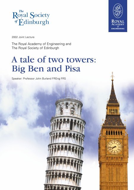
A <strong>tale</strong> <strong>of</strong> <strong>two</strong> <strong>towers</strong>:<br />
<strong>Big</strong> <strong>Ben</strong> <strong>and</strong> <strong>Pisa</strong><br />
Speaker: Pr<strong>of</strong>essor John Burl<strong>and</strong> FREng FRS
A Tale <strong>of</strong> Two Towers:<br />
<strong>Big</strong> <strong>Ben</strong> <strong>and</strong> <strong>Pisa</strong><br />
Pr<strong>of</strong>essor John Burl<strong>and</strong> DSc(Eng) FREng FRS FICE FIStructE<br />
Imperial College <strong>of</strong> Science, Technology <strong>and</strong> Medicine<br />
Born in the UK, Pr<strong>of</strong>essor Burl<strong>and</strong> was educated in<br />
South Africa <strong>and</strong> studied Civil Engineering at the<br />
University <strong>of</strong> the Witwatersr<strong>and</strong>. He returned to<br />
Engl<strong>and</strong> in 1961 <strong>and</strong> worked with Ove Arup <strong>and</strong><br />
Partners for a few years.<br />
After studying for his PhD at Cambridge University,<br />
Pr<strong>of</strong>essor Burl<strong>and</strong> joined the Building Research Station<br />
in 1966, became Head <strong>of</strong> the Geotechnics Division in<br />
1972 <strong>and</strong> Assistant Director in 1979. In 1980 he was<br />
appointed to the Chair <strong>of</strong> Soil Mechanics at the Imperial<br />
College <strong>of</strong> Science, Technology <strong>and</strong> Medicine. He is<br />
now Emeritus Pr<strong>of</strong>essor <strong>and</strong> Senior Research<br />
Investigator at Imperial College.<br />
In addition to being very active in teaching <strong>and</strong> research, John Burl<strong>and</strong> has been responsible for<br />
the design <strong>of</strong> many large ground engineering projects such as the underground car park at the<br />
Palace <strong>of</strong> Westminster <strong>and</strong> the foundations <strong>of</strong> the Queen Elizabeth II Conference Centre. He was<br />
London Underground’s expert witness for the Parliamentary Select Committees on the Jubilee<br />
Line Extension <strong>and</strong> has advised on many geotechnical aspects <strong>of</strong> that project, including ensuring<br />
the stability <strong>of</strong> the <strong>Big</strong> <strong>Ben</strong> Clock Tower. He was a member <strong>of</strong> the Italian Prime Minister’s<br />
Commission for stabilising the Leaning Tower <strong>of</strong> <strong>Pisa</strong>.<br />
He has received many awards <strong>and</strong> medals including the Kelvin Gold Medal for outst<strong>and</strong>ing<br />
contributions to Engineering <strong>and</strong> the Gold Medals <strong>of</strong> the Institution <strong>of</strong> Structural Engineers <strong>and</strong><br />
the Institution <strong>of</strong> Civil Engineers. He has been awarded three Honorary Doctorates including<br />
one from Glasgow University.<br />
Photograph courtesy <strong>of</strong> James Hunkin
2002 <strong>Royal</strong> <strong>Academy</strong> <strong>of</strong> Engineering/<br />
<strong>Royal</strong> Society <strong>of</strong> Edinburgh Lecture<br />
A Tale <strong>of</strong> Two Towers: <strong>Big</strong> <strong>Ben</strong> <strong>and</strong> <strong>Pisa</strong><br />
© Burl<strong>and</strong>, John<br />
ISBN 1-903496-04-7<br />
February 2002<br />
Published by<br />
THE ROYAL ACADEMY OF ENGINEERING<br />
29 Great Peter Street, Westminster, London SW1P 3LW<br />
Telephone 020 7222 2688 Facsimile 020 7233 0054<br />
www.raeng.org.uk<br />
The <strong>Royal</strong> <strong>Academy</strong> <strong>of</strong> Engineering is a Registered Charity (No. 293074)
A Tale <strong>of</strong> Two Towers:<br />
<strong>Big</strong> <strong>Ben</strong> <strong>and</strong> <strong>Pisa</strong><br />
1. INTRODUCTION<br />
A Tale <strong>of</strong> Two Towers<br />
This lecture tells the story <strong>of</strong> the movements <strong>of</strong> <strong>two</strong> world famous <strong>towers</strong> resulting from nearby<br />
construction activities <strong>and</strong> the application <strong>of</strong> novel geotechnical protective measures.<br />
The <strong>Big</strong> <strong>Ben</strong> Clock Tower was<br />
constructed in 1858, soon after the old<br />
Houses <strong>of</strong> Parliament were destroyed<br />
by fire. The clock tower consists <strong>of</strong><br />
load-bearing brickwork with stone<br />
cladding rising to a height <strong>of</strong> 61m; this<br />
supports a cast-iron framed spire, giving<br />
a total height <strong>of</strong> 92m. The tower is<br />
supported on a mass concrete raft 15m<br />
square <strong>and</strong> 3m thick which is founded<br />
within the Terrace Gravels <strong>of</strong> the River<br />
Thames, at a depth <strong>of</strong> about 7m below<br />
ground level. The tower is estimated to<br />
have a weight <strong>of</strong> 85MN, giving an<br />
average bearing pressure <strong>of</strong> about 400kPa. The clock face is<br />
55m above ground level <strong>and</strong> is out <strong>of</strong> plumb towards the northwest<br />
by 220mm. Thus the inclination is about 1/250 - an<br />
amount which is <strong>of</strong>ten quoted as being just discernable to the<br />
casual onlooker. This explains why tourists are <strong>of</strong>ten seen<br />
debating the verticality <strong>of</strong> the clock-tower!<br />
The Leaning Tower <strong>of</strong> <strong>Pisa</strong> st<strong>and</strong>s within the Piazza dei<br />
Miracole <strong>and</strong> is the bell tower <strong>of</strong> the magnificent Romanesque<br />
Cathedral. The tower is an architectural gem <strong>and</strong> would be<br />
one <strong>of</strong> the most important monuments <strong>of</strong> medieval Europe<br />
even if it were not leaning. The <strong>Pisa</strong> tower is very nearly 60m<br />
high, has a 20m diameter masonry foundation <strong>and</strong> weighs<br />
145MN. The foundation rests on a deep deposit <strong>of</strong> very s<strong>of</strong>t<br />
estuarine <strong>and</strong> marine sediments. The tower leans due south<br />
<strong>and</strong> in 1990 the seventh level, which forms the base <strong>of</strong> the bell<br />
chamber, overhung the ground by 4.5m. It is estimated that<br />
Aerial view <strong>of</strong> the <strong>Big</strong> <strong>Ben</strong> Clock Tower <strong>and</strong> the Palace <strong>of</strong> Westminster<br />
The Leaning Tower <strong>of</strong> <strong>Pisa</strong><br />
The <strong>Royal</strong> <strong>Academy</strong> <strong>of</strong> Engineering<br />
3
A Tale <strong>of</strong> Two Towers<br />
Vertical cross-section through the Leaning<br />
Tower <strong>of</strong> <strong>Pisa</strong><br />
4<br />
The <strong>Royal</strong> <strong>Academy</strong> <strong>of</strong> Engineering<br />
the bearing pressure beneath the south edge <strong>of</strong> the<br />
foundation is about 1000kPa. Construction <strong>of</strong> the tower<br />
began in 1173 <strong>and</strong> took place in three stages. By 1178 the<br />
fourth level had been reached when work ceased for<br />
nearly 100 years. Between 1272 <strong>and</strong> 1278 construction<br />
took place up to the seventh level when work again<br />
ceased. Finally in 1360 work on the bell chamber<br />
commenced <strong>and</strong> was completed in about 1370. Our<br />
calculations show that if the long pauses between the<br />
three phases <strong>of</strong> construction had not taken place the tower<br />
would have fallen over. The pauses allowed consolidation<br />
<strong>of</strong> the s<strong>of</strong>t sediments to take place thereby increasing the<br />
strength <strong>of</strong> the ground. There is one further important<br />
historical feature relating to the construction <strong>of</strong> the tower.<br />
In 1838 the architect Aless<strong>and</strong>ro della Gherardesca<br />
excavated a walk-way (catino) around the base <strong>of</strong> the<br />
tower. It is known that the tower lurched to the south by<br />
nearly half a metre which brought it very close to<br />
collapse. Because <strong>of</strong> fears for its stability brought about by the collapse <strong>of</strong> a bell tower in Pavia<br />
in 1989, the <strong>Pisa</strong> Tower was closed to the public in January 1990 <strong>and</strong> the Italian Prime Minister<br />
set up a Commission in March 1990, under the chairmanship <strong>of</strong> Pr<strong>of</strong>essor Michele<br />
Jamiolkowski, to implement stabilisation measures.<br />
2. CONSTRUCTION OF THE UNDERGROUND CAR PARK AT THE PALACE OF<br />
WESTMINSTER<br />
Model <strong>of</strong> the underground car park at the<br />
Palace <strong>of</strong> Westminster<br />
In the early 1970’s an 18.5m deep underground car park<br />
was constructed in New Palace Yard <strong>and</strong> the project is<br />
described by Burl<strong>and</strong> <strong>and</strong> Hancock (1977) 1 . The<br />
excavation comes to within 16m <strong>of</strong> the <strong>Big</strong> <strong>Ben</strong> Clock<br />
Tower <strong>and</strong> 3m <strong>of</strong> Westminster Hall. It was constructed<br />
using what is termed ‘top-down’ construction. The pile<br />
foundations <strong>and</strong> reinforced concrete diaphragm retaining<br />
walls were constructed first. Then the ground floor was<br />
cast <strong>and</strong> thereafter excavation took place downwards with<br />
successive floors being constructed from the top<br />
downwards. This method provides very effective support<br />
to the retaining walls thereby minimising surrounding<br />
surface ground movements. It is also environmentally<br />
friendly since it reduces noise <strong>and</strong> dust during construction.
A Tale <strong>of</strong> Two Towers<br />
Ground movements <strong>and</strong> possible building damage were <strong>of</strong> major concern for this project<br />
situated as it is close to priceless historic buildings. The Department <strong>of</strong> the Environment called<br />
in the Building Research Establishment to advise on the project. Predictions <strong>of</strong> the ground<br />
movements were made using computer modelling. This is one <strong>of</strong> the earliest examples <strong>of</strong> the<br />
application <strong>of</strong> the finite element method in geotechnical design. For the analysis the London<br />
clay was assumed to behave in a linearly elastic way <strong>and</strong> laboratory testing at that time<br />
supported the use <strong>of</strong> such simple behaviour. The assumed values <strong>of</strong> Young’s modulus increased<br />
with depth <strong>and</strong> were based on the back-analysis <strong>of</strong> measurements <strong>of</strong> retaining wall movements<br />
<strong>of</strong> other excavations in London Clay (Cole <strong>and</strong> Burl<strong>and</strong>, 1972 2 ). The predictions from the<br />
computer model were published prior to commencement <strong>of</strong> the work (Ward <strong>and</strong> Burl<strong>and</strong>,<br />
1972 3 ). Such a prediction published prior to construction has come to be known as a Class A<br />
prediction.<br />
The graph adjacent shows the observed<br />
inward displacements <strong>of</strong> the southerly<br />
retaining wall on completion <strong>of</strong> excavation<br />
(full line) which can be compared with the<br />
Class A prediction. It can be seen that the<br />
agreement, though not perfect, is very<br />
reasonable. The situation proved to be far less<br />
satisfactory for the ground surface<br />
movements around the excavation.The graph<br />
below shows the horizontal <strong>and</strong> vertical<br />
surface movements with distance from the<br />
edge <strong>of</strong> the retaining walls. The points show<br />
measurements made on various buildings<br />
<strong>and</strong> the full line shows the class A prediction.<br />
It can be seen that, although the<br />
predicted horizontal movements are<br />
once again in reasonable agreement<br />
with the observations, the shape <strong>of</strong><br />
the predicted settlement pr<strong>of</strong>ile<br />
differs significantly from the<br />
observations. The observed<br />
settlements were concentrated much<br />
closer to the edge <strong>of</strong> the excavation<br />
than the predicted values <strong>and</strong> were<br />
larger than them. A consequence <strong>of</strong><br />
this was that, whereas the <strong>Big</strong> <strong>Ben</strong><br />
Clock Tower was predicted to tilt<br />
away from the excavation by about<br />
1/6000 it actually tilted towards the<br />
excavation by about 1/7000. We had<br />
got the magnitude about right but the<br />
direction wrong!<br />
Observed <strong>and</strong> predicted horizontal displacements <strong>of</strong> the<br />
Observed <strong>and</strong> predicted ground surface displacements outside<br />
the car park<br />
The <strong>Royal</strong> <strong>Academy</strong> <strong>of</strong> Engineering<br />
5
A Tale <strong>of</strong> Two Towers<br />
We found this result very puzzling. However, shortly after we published our measurements<br />
(Burl<strong>and</strong> <strong>and</strong> Hancock, 1977 1 ), Dr Brian Simpson FREng <strong>of</strong> Ove Arup showed that, by using a<br />
bilinear stress-strain law with a high initial stiffness, the agreement between observations <strong>and</strong><br />
predictions could be greatly improved - particularly with respect to the vertical movements as<br />
shown by the broken lines in the <strong>two</strong> graphs on page 5 (Simpson et al, 1979 4 ). Simultaneously<br />
with this theoretical work, Pr<strong>of</strong>essor Vaughan FREng began laboratory studies at Imperial<br />
College in which axial strains were measured locally on soil samples instead <strong>of</strong> between the<br />
end plattens as had traditionally been done. These measurements gave highly non-linear stressstrain<br />
behaviour with stiffnesses at small strains which were much larger than those inferred<br />
from traditional measurements. It now became clear that the pattern <strong>of</strong> ground movements<br />
observed at New Palace Yard, in which the vertical movements are concentrated close to the<br />
edge <strong>of</strong> the excavation, is due to the non-linear nature <strong>of</strong> the stress-strain behaviour <strong>of</strong> the soil.<br />
This process <strong>of</strong> prior publication <strong>of</strong> predictions, though uncomfortable at the time, has proved<br />
highly beneficial as it forced us all to ponder long <strong>and</strong> hard as to the explanation for the<br />
discrepancies. Without such public disclosure it would have been all too tempting to quietly<br />
ignore the discrepancies <strong>and</strong> move on to other things. The work at New Palace Yard <strong>and</strong> the<br />
measured response <strong>of</strong> the Clock Tower has spawned a whole new important area <strong>of</strong> study <strong>of</strong> the<br />
behaviour <strong>of</strong> the ground at small strains - indeed whole international conferences are now<br />
devoted to the subject. These studies are proving vitally important for modelling interaction<br />
effects between ground <strong>and</strong> structure, particularly in the urban environment where underground<br />
construction is a vital part <strong>of</strong> infrastructure development. We now travel to Italy to consider the<br />
challenges faced by the <strong>Pisa</strong> Commission.<br />
3. MOVEMENTS OF THE PISA TOWER<br />
The ground underlying the <strong>Pisa</strong> Tower consists <strong>of</strong> three distinct layers. Layer A is about 10m<br />
thick <strong>and</strong> primarily consists <strong>of</strong> s<strong>of</strong>t estuarine deposits <strong>of</strong> s<strong>and</strong>y <strong>and</strong> clayey silts laid down under<br />
tidal conditions. Layer B consists <strong>of</strong> s<strong>of</strong>t<br />
sensitive normally consolidated marine clay<br />
which extends to a depth <strong>of</strong> about 40m. This<br />
material is very sensitive <strong>and</strong> loses much <strong>of</strong> its<br />
strength if disturbed. Layer C is a dense s<strong>and</strong><br />
which extends to considerable depth. The<br />
water table in Horizon A is between 1m <strong>and</strong><br />
2m below ground surface. The surface <strong>of</strong> the<br />
marine clay is dished beneath the Tower<br />
showing that the average settlement is between<br />
2.5m <strong>and</strong> 3.0m - a good indication <strong>of</strong> how very<br />
s<strong>of</strong>t the ground is.<br />
The axis <strong>of</strong> the tower is not straight - it bends to<br />
the north. In an attempt to correct the lean during construction the masons placed tapered<br />
blocks <strong>of</strong> masonry at the level <strong>of</strong> each floor to bend the axis <strong>of</strong> the tower away from the lean.<br />
6<br />
The <strong>Royal</strong> <strong>Academy</strong> <strong>of</strong> Engineering<br />
Soil pr<strong>of</strong>ile beneath the Leaning Tower <strong>of</strong> <strong>Pisa</strong>
A Tale <strong>of</strong> Two Towers<br />
Careful analysis <strong>of</strong> the relative inclinations <strong>of</strong> the masonry layers has revealed the history <strong>of</strong> the<br />
tilting <strong>of</strong> the tower. At the end <strong>of</strong> the first construction phase it was actually leaning northwards<br />
by about one quarter <strong>of</strong> a degree. Then, as construction advanced above the fourth storey,<br />
it began to move towards the south <strong>and</strong> accelerate so that by 1278, when the seventh level had<br />
been reached, it was inclining southwards by about 0.6 <strong>of</strong> a degree. This had increased to about<br />
1.6 degrees by 1360 when work on the bell chamber commenced. In 1817 <strong>two</strong> British architects<br />
used a plumb line to measure the inclination which by then was 5 degrees. Thus the<br />
construction <strong>of</strong> the bell chamber caused a very significant increase in inclination. Advanced<br />
computer modelling has revealed that the rapid increase in inclination as the seventh level was<br />
reached <strong>and</strong> the bell chamber was added is directly analogous to constructing a tower from<br />
model bricks on a s<strong>of</strong>t carpet (Burl<strong>and</strong> <strong>and</strong> Potts, 1994 5 ). It is possible to build to a certain<br />
critical height, but no higher, however careful one is - a phenomenon known as leaning<br />
instability. The tower was just at its critical height <strong>and</strong> was very close to falling over! The<br />
excavation <strong>of</strong> the catino brought the tower even closer to collapse.<br />
Precise measurements begun in 1911 show that during the twentieth century the inclination <strong>of</strong><br />
the tower has been increasing inexorably each year <strong>and</strong> the rate <strong>of</strong> tilt has doubled since the<br />
1930’s. In 1990 the rate <strong>of</strong> tilt was equivalent to a horizontal movement at the top <strong>of</strong> about<br />
1.5mm per year. Moreover any interference with the tower resulted in significant increases in<br />
tilt. For example, in 1934 consolidation <strong>of</strong> the foundation masonry by means <strong>of</strong> grout injection<br />
resulted in a sudden movement south <strong>of</strong> about 10mm <strong>and</strong> ground water abstraction from the<br />
lower s<strong>and</strong>s in the 1970’s resulted in an increase in movement <strong>of</strong> about 12mm. These responses<br />
confirm how very sensitively poised the tower was <strong>and</strong> how delicate any method <strong>of</strong> stabilisation<br />
would have to be.<br />
There has been much debate about the cause <strong>of</strong> this progressive increase in inclination. It has<br />
usually been attributed to creep in the underlying s<strong>of</strong>t marine clay, the assumption being made<br />
that the south side was settling more than the north side.<br />
A careful study <strong>of</strong> the geodetic survey measurements<br />
going back to 1911 revealed a most surprising form <strong>of</strong><br />
motion <strong>of</strong> the foundations which was radically different to<br />
previously held ideas. The theodolite measurements onto<br />
the first cornice (V1 in the diagram on page 4) showed that<br />
it had not moved horizontally - apart from <strong>two</strong> occasions<br />
when man had intervened. Also precision level measurements<br />
which commenced in 1928 showed that the centre <strong>of</strong><br />
the foundations had not displaced vertically relative to the<br />
surrounding ground. Therefore the rigid body motion <strong>of</strong><br />
the Tower could only be as shown here, with an<br />
instantaneous centre <strong>of</strong> rotation at the level <strong>of</strong> the first<br />
cornice vertically above the centre <strong>of</strong> the foundations.<br />
The direction <strong>of</strong> motion <strong>of</strong> points F N <strong>and</strong> F S are shown by<br />
vectors <strong>and</strong> it is clear that the foundations have been<br />
moving northwards with F N rising <strong>and</strong> F S sinking.<br />
Motion <strong>of</strong> Tower foundations during<br />
progressive increase in inclination<br />
The <strong>Royal</strong> <strong>Academy</strong> <strong>of</strong> Engineering<br />
7
A Tale <strong>of</strong> Two Towers<br />
The discovery that the motion <strong>of</strong> the Tower was as shown has turned out to be crucial in three<br />
respects:<br />
1. The observation that the north side had been steadily rising led directly to the suggestion<br />
that the application <strong>of</strong> a lead counterweight to the foundation masonry on the north side could<br />
be beneficial as a temporary stabilising measure by reducing the overturning moment.<br />
2. The pattern <strong>of</strong> ground movements depicted led to the very important conclusion that the seat<br />
<strong>of</strong> the continuing long-term rotation <strong>of</strong> the Tower lies in horizon A <strong>and</strong> not within the underlying<br />
marine clay as had been widely assumed in the past. It can therefore be concluded that the<br />
latter stratum must have undergone a considerable period <strong>of</strong> ageing since last experiencing<br />
significant deformation (which was probably in 1838 when Gherardesca excavated the catino).<br />
This ageing resulted in an increased resistance to yield - a conclusion that proved to be <strong>of</strong> great<br />
importance in the successful modelling <strong>of</strong> the application <strong>of</strong> the temporary counterweights.<br />
3. In the light <strong>of</strong> the measured motion <strong>of</strong> the Tower foundations, <strong>and</strong> consistent with the seat <strong>of</strong><br />
the movement lying within Horizon A, it was concluded that the most likely cause <strong>of</strong> the<br />
progressive seasonal rotation was a seasonally fluctuating ground-water level in Horizon A due<br />
to seasonal heavy rainstorms that always occur in the period September to December each<br />
year. Accordingly a number <strong>of</strong> st<strong>and</strong>-pipes were installed in this Horizon around the Tower.<br />
Measurement made over a four year period have confirmed this hypothesis - commencement <strong>of</strong><br />
rotation each year coincides with very sharp rises in the ground water level in the Horizon<br />
following each heavy rainstorm. Measures have been proposed to stabilise the ground water<br />
levels beneath the Tower.<br />
It is true to say that the identification <strong>of</strong> the form <strong>of</strong> motion <strong>of</strong> the foundations <strong>of</strong> the Leaning<br />
Tower <strong>of</strong> <strong>Pisa</strong> is the single most important finding in the development <strong>of</strong> the strategy for<br />
temporary stabilisation in which 600t <strong>of</strong> lead weights were placed on a concrete ring clamped to<br />
the base <strong>of</strong> the Tower by circumferential post-tensioning. This measure was implemented<br />
between July 1993 <strong>and</strong> January 1994 <strong>and</strong> proved to be very effective.<br />
Immediately following the application <strong>of</strong> the lead weights, activities commenced in London<br />
alongside the <strong>Big</strong> <strong>Ben</strong> Clock Tower that required urgent attention. We therefore have to return<br />
to London to attend to these <strong>and</strong> leave the Tower for a while to ponder on its permanent<br />
stabilisation.<br />
4. THE INFLUENCE OF THE JUBILEE LINE EXTENSION ON THE BIG BEN<br />
CLOCK TOWER<br />
The construction <strong>of</strong> Westminster Station on London Underground Limited’s new Jubilee Line<br />
Extension (JLE) was predicted to produce significant movements <strong>of</strong> the <strong>Big</strong> <strong>Ben</strong> Clock Tower<br />
(Harris et al 2000 6<br />
). A north-south cross-section through the new Westminster Station <strong>and</strong> the<br />
Clock Tower is shown in opposite. The Station consists <strong>of</strong> <strong>two</strong> 7.4m diameter platform tunnels<br />
in a vertically stacked arrangement below Bridge Street at depths <strong>of</strong> 21m <strong>and</strong> 30m below<br />
ground level. Alongside is a 39m deep excavation which forms an underground ‘box’ to house<br />
the access escalators <strong>and</strong> is the deepest basement ever to have been constructed in London.<br />
8<br />
The <strong>Royal</strong> <strong>Academy</strong> <strong>of</strong> Engineering
A Tale <strong>of</strong> Two Towers<br />
Prior to any substantial excavation within the station escalator box, the 4.85m diameter running<br />
tunnels were driven as pilot tunnels. The lowest west-bound tunnel was constructed in March<br />
1995 <strong>and</strong> the upper east-bound tunnel in October 1995. The running tunnels were then<br />
enlarged to 7.4m diameter to form the platform tunnels, the westbound <strong>and</strong> east-bound<br />
enlargements being carried out in February 1996 <strong>and</strong> November 1996 respectively.<br />
The retaining walls for the station box consist <strong>of</strong> reinforced concrete diaphragm walls. Like the<br />
adjacent Palace <strong>of</strong> Westminster car park, excavation was carried out using the top-down<br />
method with the struts <strong>and</strong> floors being installed progressively from the top down as excavation<br />
progressed. In order to minimise surrounding ground movements, low-level struts were installed<br />
in tunnels close to the base <strong>of</strong> the diaphragm walls prior to excavation below the main ro<strong>of</strong><br />
slab. Excavation within the diaphragm walls was undertaken between September 1995 <strong>and</strong><br />
September 1997.<br />
Careful computer modelling <strong>of</strong> the<br />
tunnelling <strong>and</strong> excavation was carried<br />
out <strong>and</strong> was greatly aided by the<br />
measurements made during the<br />
construction <strong>of</strong> the underground car park<br />
in the 1970’s. Despite the provision <strong>of</strong><br />
very stiff diaphragm walls <strong>and</strong> low level<br />
tunnelling struts, it was recognised that<br />
the combination <strong>of</strong> the <strong>two</strong> platform<br />
tunnels <strong>and</strong> the station box could lead to<br />
unacceptable tilting <strong>of</strong> the Clock Tower.<br />
The concern was that excessive tilting<br />
would lead to cracking where the Tower<br />
<strong>and</strong> the Palace <strong>of</strong> Westminster were<br />
connected. A contingency protective measure<br />
was called for <strong>and</strong> the relatively new<br />
technique <strong>of</strong> compensation grouting was adopted.<br />
Cross-section showing proximity <strong>of</strong> the new Westminster station<br />
to <strong>Big</strong> <strong>Ben</strong><br />
The principle <strong>of</strong> compensation grouting is to inject grout (a mixture <strong>of</strong> cement, s<strong>and</strong> <strong>and</strong> water)<br />
under pressure into the ground at chosen locations so as to counter any subsidence that an<br />
overlying building might be experiencing. This is done by installing into the ground a number <strong>of</strong><br />
steel tubes (known as TAMs, the abbreviation for ‘tubes à manchettes’) with holes machined<br />
into them at regular intervals, typically about 0.3m. Covering each hole is a short rubber sleeve<br />
which acts as a one-way valve allowing grout to be pumped out under pressure without flowing<br />
back in. Any hole can be selected for grout injection <strong>and</strong> the system allows repeated grouting<br />
through the same hole if required.<br />
The provision <strong>of</strong> grouting tubes below one <strong>of</strong> London’s busiest areas was not a simple matter<br />
<strong>and</strong> the horizontal array <strong>of</strong> grouting tubes were installed by drilling radially outwards from a<br />
vertical shaft which was located in the middle <strong>of</strong> Bridge Street. The tubes were about 50m long<br />
<strong>and</strong> were drilled beneath the foundation <strong>of</strong> the Clock Tower <strong>and</strong> immediately to the north.<br />
The <strong>Royal</strong> <strong>Academy</strong> <strong>of</strong> Engineering<br />
9
A Tale <strong>of</strong> Two Towers<br />
The elevation <strong>of</strong> the tubes was chosen so that they were just within the London Clay to avoid<br />
encountering the ground water in the overlying gravel. Sixteen tubes were installed beneath the<br />
foundation having a maximum spacing <strong>of</strong> about 2.5m.<br />
The graph below shows the measured tilt <strong>of</strong> the Clock Tower throughout the construction period<br />
<strong>and</strong> for three years afterwards. The tilt is expressed as horizontal movements northwards in<br />
mm at a height <strong>of</strong> 55m. The dates <strong>of</strong> the various construction activities are indicated on the<br />
figure: the passage <strong>of</strong> the four tunnel drives are shown across the top <strong>of</strong> the figure <strong>and</strong> the dates<br />
<strong>of</strong> installation <strong>of</strong> the props at various depths within the escalator box are shown along the<br />
bottom. The maximum permissible limit on the change in tilt had been set at 1/2000 which is<br />
equivalent to 27.5mm at a height <strong>of</strong> 55m. A trigger level for initiating grouting was set 1/2500<br />
Tilt <strong>of</strong> Clock Tower (mm/55m)<br />
10<br />
40<br />
30<br />
20<br />
10<br />
0<br />
Tunnel Progress:<br />
Pilots Enlargements<br />
WB EB WB EB<br />
Construction<br />
Control<br />
Range<br />
Grouting Episodes<br />
Start <strong>of</strong><br />
Grouting<br />
Box Excavation<br />
Progress [m]:<br />
9 1 3 16 22 25 31 35 39<br />
-10<br />
Nov-94 Nov-95 Nov-96 Nov-97 Nov-98 Nov-99 Nov-2000<br />
Optical Plumb<br />
Measured horizontal movements <strong>of</strong> <strong>Big</strong> <strong>Ben</strong> at clock face level between 1994<br />
<strong>and</strong> 2000<br />
The <strong>Royal</strong> <strong>Academy</strong> <strong>of</strong> Engineering<br />
(22mm). A construction control<br />
range <strong>of</strong> between 15mm <strong>and</strong><br />
25mm tilt was adopted.<br />
As anticipated, northward tilt <strong>of</strong><br />
the Clock Tower commenced as<br />
the west-bound running tunnel<br />
passed by <strong>and</strong> an immediate tilt<br />
<strong>of</strong> 4mm was recorded. Time<br />
dependent movements then took<br />
place <strong>and</strong> it became clear that it<br />
would be necessary to implement<br />
compensation grouting in order<br />
to keep the tilt <strong>of</strong> the Clock<br />
Tower within permissible limits.<br />
Between February 1996 <strong>and</strong><br />
September 1997, when the deepest level <strong>of</strong> the escalator box was reached, grouting was<br />
undertaken to keep the tilt within the construction control range <strong>and</strong> this was generally<br />
achieved. Altogether 24 grouting episodes were undertaken in which a total volume <strong>of</strong> 122m 3<br />
<strong>of</strong> grout was injected. Without any compensation grouting the cumulative increase in tilt <strong>of</strong> the<br />
Clock Tower would have been at least 120mm which would certainly have resulted in<br />
significant cracking <strong>of</strong> the Palace <strong>of</strong> Westminster.<br />
Since the end <strong>of</strong> construction, no further grouting has been undertaken. It can be seen from the<br />
graph above that time-dependent tilt has continued at a decreasing rate. This is consistent with<br />
computer predictions <strong>and</strong> is still being monitored very closely. The measurements indicate that<br />
the long-term tilt has almost stabilised at around 35mm. The damage to the Palace <strong>of</strong><br />
Westminster has been very localised <strong>and</strong> very slight.<br />
The innovative technique <strong>of</strong> compensation grouting, which has never before been applied to a<br />
structure as fragile <strong>and</strong> <strong>of</strong> such historic importance as the <strong>Big</strong> <strong>Ben</strong> Clock Tower, has been<br />
extremely successful <strong>and</strong> is a great credit to the contractor, Balfour Beatty/AMEC. In the<br />
controversy that surrounds London Underground, the successful construction <strong>of</strong> the Jubilee<br />
Line Extension has not been given the recognition that it deserves.
A Tale <strong>of</strong> Two Towers<br />
The problems at <strong>Pisa</strong> are now pressing <strong>and</strong> we need to return there to decide on the permanent<br />
stabilisation measures.<br />
5. STABILISATION OF THE PISA TOWER USING SOIL EXTRACTION<br />
The internationally accepted conventions for the conservation <strong>of</strong> valuable historic monuments<br />
requires that their essential character should be preserved, together with their history,<br />
craftsmanship <strong>and</strong> enigmas. Thus any invasive interventions on the Tower had to be kept to an<br />
absolute minimum <strong>and</strong> permanent stabilisation schemes involving propping or visible support<br />
were unacceptable <strong>and</strong> in any case could have triggered the collapse <strong>of</strong> the fragile masonry.<br />
As described on our previous visit to <strong>Pisa</strong>, temporary stabilisation <strong>of</strong> the foundations was<br />
achieved during the second half <strong>of</strong> 1993 by the application <strong>of</strong> 600t <strong>of</strong> lead weights to the north<br />
side <strong>of</strong> the foundations via a post-tensioned removable concrete ring cast around the base <strong>of</strong> the<br />
Tower at plinth level. This caused a reduction in inclination <strong>of</strong> about one minute <strong>of</strong> arc <strong>and</strong>,<br />
more importantly, reduced the overturning moment by about ten percent. In September 1995<br />
the load was increased to 900t in order to control the movements <strong>of</strong> the Tower during an<br />
unsuccessful attempt to replace the unsightly lead weights with temporary ground anchors.<br />
A permanent solution was sought that would result in a small reduction in inclination by about<br />
half a degree which is not enough to be visible but which would reduce the stresses in the<br />
masonry <strong>and</strong> stabilise the foundations. Given that the foundation <strong>of</strong> the Tower was on the point<br />
<strong>of</strong> instability <strong>and</strong> that any slight disturbance to the ground on the south side would almost<br />
certainly trigger collapse, finding a method <strong>of</strong> reducing the inclination was far from straight<br />
forward <strong>and</strong> gave rise to many heated debates within the Commission. Many possible methods<br />
<strong>of</strong> inducing controlled subsidence <strong>of</strong> the north side were investigated. These included drainage<br />
by means <strong>of</strong> wells, consolidation beneath the north side by electro-osmosis <strong>and</strong> loading the<br />
ground around the north side <strong>of</strong> the Tower by means <strong>of</strong> a pressing slab pulled down by ground<br />
anchors. None <strong>of</strong> these methods proved satisfactory.<br />
A method known as soil extraction<br />
gradually evolved. This involves<br />
installing a number <strong>of</strong> soil extraction<br />
tubes adjacent to <strong>and</strong> just beneath<br />
the north side <strong>of</strong> the foundation as<br />
illustrated . The method had been<br />
successfully used previously,<br />
notably to reduce the damaging<br />
differential settlements within the<br />
Metropolitan Cathedral <strong>of</strong> Mexico<br />
City. But using it on a tower that<br />
was on the point <strong>of</strong> falling over was<br />
altogether another matter. How<br />
could we be sure that removal <strong>of</strong> soil<br />
Location <strong>of</strong> soil extraction tubes adjacent to <strong>and</strong> beneath the Tower<br />
The <strong>Royal</strong> <strong>Academy</strong> <strong>of</strong> Engineering<br />
11
A Tale <strong>of</strong> Two Towers<br />
from beneath the high side would not create instability <strong>of</strong> the Tower? Over a number <strong>of</strong> years<br />
the method was studied first by means <strong>of</strong> physical models, then by numerical modelling <strong>and</strong><br />
finally by means <strong>of</strong> a large-scale trial. A key finding from the model studies <strong>and</strong> numerical<br />
analysis was the existence <strong>of</strong> a critical line located about half a radius in from the northern edge<br />
<strong>of</strong> the foundation. Provided soil extraction from beneath the foundation took place north <strong>of</strong> this<br />
line the response <strong>of</strong> the Tower appeared always to be positive. However, if extraction took<br />
place south <strong>of</strong> this line the Tower would become unstable.<br />
Using a large-scale trial foundation in the Piazza, a drill was developed by the contractor Trevi<br />
which consisted <strong>of</strong> a hollow-stemmed continuous flight auger (otherwise known as an<br />
Archimedes screw) housed inside a contra-rotating 180mm diameter casing. This arrangement<br />
ensured that the drill could be advanced without any disturbance to the surrounding ground.<br />
The sequence <strong>of</strong> operations for carrying out an extraction is illustrated below. The trials showed<br />
that the cavities formed in the silty soil <strong>of</strong> Layer A closed gently <strong>and</strong> that repeated extractions<br />
could be made from the same location. The trial<br />
foundation was successfully rotated by about 0.25 o <strong>and</strong><br />
directional control was maintained even though the<br />
ground conditions were somewhat non-uniform. Very<br />
importantly, an effective system <strong>of</strong> communication,<br />
decision taking <strong>and</strong> implementation was developed.<br />
In August 1996 the Commission agreed to carry out<br />
limited soil extraction from beneath the Tower with a<br />
view to observing its response. A target <strong>of</strong> a minimum<br />
<strong>of</strong> 20 arc seconds reduction in inclination was set as<br />
being large enough to demonstrate unequivocally the<br />
effectiveness <strong>of</strong> the system. Due to bureaucratic <strong>and</strong><br />
administrative delays it was not until the end <strong>of</strong> 1998<br />
that preparatory work actually began. In December<br />
1998 some temporary safeguard cables were attached<br />
to the third storey <strong>of</strong> the Tower. These stretched<br />
horizontally some 100m north <strong>of</strong> the Tower, passed<br />
over pulleys on the top <strong>of</strong> <strong>two</strong> massive A frames <strong>and</strong><br />
Sequence <strong>of</strong> operations <strong>of</strong> the soil extraction drill<br />
were lightly tensioned by means <strong>of</strong> lead weights. In<br />
the event <strong>of</strong> adverse movements <strong>of</strong> the Tower these<br />
safeguard cables could be tensioned by adding additional lead weights to hold the Tower<br />
steady. It was never intended that they should be used to actually move the Tower northward.<br />
Preliminary soil extraction was carried out over a limited width <strong>of</strong> 6m using twelve bore holes<br />
lined with 220mm diameter casings. The auger <strong>and</strong> rotating casing had to be moved from hole to<br />
hole so that the operation was slow <strong>and</strong> cumbersome with a maximum <strong>of</strong> <strong>two</strong> extractions each<br />
day. The carefully developed system <strong>of</strong> communication <strong>and</strong> control involved a system <strong>of</strong> twice<br />
daily faxes from the site containing real-time information on the inclination <strong>and</strong> settlement <strong>of</strong> the<br />
Tower. A daily fax was issued by the responsible engineer (the author) summarising the<br />
12<br />
The <strong>Royal</strong> <strong>Academy</strong> <strong>of</strong> Engineering
A Tale <strong>of</strong> Two Towers<br />
observed response, commenting on it <strong>and</strong> then giving a signed instruction for the next<br />
extraction operation with clearly stated objectives. It was rather like riding a bicycle by fax!<br />
Green, amber <strong>and</strong> red trigger levels were<br />
set for taking action in the event <strong>of</strong><br />
adverse responses <strong>of</strong> the Tower. These<br />
included both rates <strong>and</strong> magnitudes <strong>of</strong><br />
changes <strong>of</strong> inclination <strong>and</strong> settlement.<br />
The trigger levels were set after a careful<br />
study <strong>of</strong> about six years <strong>of</strong> records <strong>of</strong><br />
movements <strong>of</strong> the Tower so as to avoid<br />
over stringent requirements <strong>and</strong> false<br />
alarms.<br />
On 9th February 1999, in an atmosphere<br />
<strong>of</strong> great tension, the first soil extraction<br />
took place. For the first few days, as the<br />
Results <strong>of</strong> soil extraction<br />
drills were advanced towards the edge <strong>of</strong><br />
the foundation, the Tower showed no<br />
discernable response. Then slowly it began to rotate northwards. The results <strong>of</strong> preliminary soil<br />
extraction are shown at the left h<strong>and</strong> side <strong>of</strong> this figure. When the northward rotation had<br />
reached about 80 arc seconds by early June 1999 soil extraction was stopped. Northward<br />
rotation continued at a decreasing rate until July 1999 when three <strong>of</strong> the lead weights were<br />
removed whereupon all movement ceased.<br />
The success <strong>of</strong> preliminary soil extraction persuaded the Commission that it was safe to<br />
undertake full soil extraction over the full width <strong>of</strong> the foundations. Accordingly, between<br />
December 1999 <strong>and</strong> January 2000, 41 extraction holes were installed at 0.5m spacing with a<br />
dedicated auger <strong>and</strong> casing in each hole as shown below. Full soil extraction commenced on<br />
21 st February 2000 <strong>and</strong> the results <strong>of</strong> both<br />
preliminary <strong>and</strong> full soil extraction are<br />
shown above. It can be seen that a much<br />
higher rate <strong>of</strong> northward rotation was<br />
achieved than for preliminary soil<br />
extraction averaging about 6 arc seconds<br />
per day resulting from the removal <strong>of</strong> about<br />
120 litres <strong>of</strong> soil. It was gratifying to note<br />
that significant uplift <strong>of</strong> the southern edge<br />
<strong>of</strong> the foundation took place indicating a<br />
reduction in bearing pressure at this highly<br />
stressed region.<br />
Towards the end <strong>of</strong> May 2000 progressive<br />
removal <strong>of</strong> the lead ingots commenced,<br />
Drilling rig <strong>and</strong> 41 extraction tubes<br />
The <strong>Royal</strong> <strong>Academy</strong> <strong>of</strong> Engineering<br />
13
A Tale <strong>of</strong> Two Towers<br />
initially with <strong>two</strong> ingots per week (about 18t). In September 2000 this was increased to three<br />
per week <strong>and</strong> then to four per week in November 2000. Removal <strong>of</strong> the lead ingots resulted in<br />
a significant increase in overturning moment but the soil extraction continued to be effective.<br />
On 16 th January 2001 the last lead ingot was removed from the post-tensioned concrete ring <strong>and</strong><br />
thereafter only limited soil extraction was undertaken. In the middle <strong>of</strong> February the concrete<br />
ring itself was removed <strong>and</strong> at the beginning <strong>of</strong> March progressive removal <strong>of</strong> the augers <strong>and</strong><br />
casings commenced with the holes being filled by a bentonitic grout. Finally in the middle <strong>of</strong><br />
May the safeguard cables were removed from the Tower which resulted in a southward rotation<br />
<strong>of</strong> a few arc seconds. To counter this, a small amount <strong>of</strong> additional soil extraction was carried<br />
out with the final extraction <strong>and</strong> auger removal taking place on 6 th June 2001 - the date when<br />
the Tower was released by the Commission from intensive care.<br />
Pageantry during h<strong>and</strong>-over ceremony on 16 June 2001<br />
14<br />
The <strong>Royal</strong> <strong>Academy</strong> <strong>of</strong> Engineering<br />
The target reduction <strong>of</strong><br />
inclination had been half a<br />
degree, being an amount not<br />
visible to the casual observer<br />
but sufficient to stabilise the<br />
foundations <strong>and</strong> reduce the<br />
stresses in the masonry by a<br />
significant amount. In fact a<br />
total reduction <strong>of</strong> 1830 arc<br />
seconds was achieved which<br />
is equivalent to a northward<br />
movement <strong>of</strong> the seventh<br />
floor <strong>of</strong> 440mm. The Tower is<br />
now back at its inclination in<br />
1838 at the time Gherardesca<br />
dug the catino <strong>and</strong> before its<br />
dramatic lurch south.<br />
On 16 th June 2001 the Tower was formally h<strong>and</strong>ed back to the civic authorities at a colourful<br />
ceremony <strong>and</strong> celebrations continued throughout the next day to mark the feast <strong>of</strong> San Ranieri,<br />
the patron saint <strong>of</strong> <strong>Pisa</strong>. On the 15 th December 2001 the Tower was re-opened to the public<br />
nearly twelve years after it had been closed.<br />
An obvious question is how will the Tower behave in the future? Two scenarios have been<br />
developed. A pessimistic one is that the Tower will remain stable for a while, followed by a<br />
resumption <strong>of</strong> rotation southwards at a much reduced rate. With this scenario it would take<br />
over 100 years before another intervention on the foundation is required. An optimistic<br />
scenario is that continuing rotation will cease apart from small cyclic movements caused by<br />
seasonal changes in the ground water table <strong>and</strong> also the influence <strong>of</strong> differential subsidence<br />
which is affecting the whole Piazza <strong>and</strong> which is reflected in the Tower.
6. CONCLUSION<br />
A Tale <strong>of</strong> Two Towers<br />
The conservation <strong>of</strong> both the <strong>Big</strong> <strong>Ben</strong> Clock Tower <strong>and</strong> the Tower <strong>of</strong> <strong>Pisa</strong> has provided<br />
immense civil engineering challenges. Both compensation grouting <strong>and</strong> soil extraction are highly<br />
innovative methods <strong>of</strong> stabilisation that are completely consistent with the requirements <strong>of</strong><br />
architectural conservation. Their implementation has required advanced computer modelling,<br />
large-scale development trials, an exceptional level <strong>of</strong> continuous high precision monitoring <strong>and</strong><br />
carefully developed systems <strong>of</strong> day by day communication <strong>and</strong> control.<br />
REFERENCES<br />
1. J.B. Burl<strong>and</strong> <strong>and</strong> Hancock,R.J.R.(1977). Underground car park at the House <strong>of</strong> Commons,<br />
London: Geotechnical aspects. The Structural Engineer, 55;2;87-100.<br />
2. K.W. Cole <strong>and</strong> Burl<strong>and</strong>,J.B.(1972). Observations <strong>of</strong> retaining wall movements associated<br />
with a large excavation. Proc. 5th European Conf. on Soil Mechanics <strong>and</strong> Foundation<br />
Engineering, Madrid 1972, 1;445-453.<br />
3. W.H. Ward <strong>and</strong> Burl<strong>and</strong>,J.B.(1972). The use <strong>of</strong> ground strain measurements in civil engineering.<br />
Phil. Trans. <strong>Royal</strong> Soc, London, A, 274, pp 421-428.<br />
4. B. Simpson, O’ Riordan, N.J. <strong>and</strong> Cr<strong>of</strong>t, D.D. (1979). A computer model for the analysis <strong>of</strong><br />
ground movements in London Clay. Geotechnique 29, No 2, 149-175<br />
5. J.B.Burl<strong>and</strong> <strong>and</strong> Potts,D.M.(1994). Development <strong>and</strong> application <strong>of</strong> a numerical model for<br />
the Leaning Tower <strong>of</strong> <strong>Pisa</strong>. Proc. Int. Symp. on Pre-failure Deformation Characteristics<br />
<strong>of</strong> Geo-materials, Hokkaido, Japan, Vol 2; 715-738.<br />
6. D.I.Harris, Mair, R.J., Burl<strong>and</strong>, J.B.<strong>and</strong> St<strong>and</strong>ing, J.R.(2000). Compensation grouting to<br />
control tilt <strong>of</strong> <strong>Big</strong> <strong>Ben</strong> Clock Tower. Geotechnical Aspects <strong>of</strong> Underground Construction<br />
in S<strong>of</strong>t Ground. Ed. by Kusakabe, Fujita & Miyazaki, Balkema, 2000, p.225-232.<br />
The <strong>Royal</strong> <strong>Academy</strong> <strong>of</strong> Engineering<br />
15
A Tale <strong>of</strong> Two Towers<br />
16<br />
The <strong>Royal</strong> <strong>Academy</strong> <strong>of</strong> Engineering
The <strong>Royal</strong> <strong>Academy</strong> <strong>of</strong> Engineering<br />
The objectives <strong>of</strong> The <strong>Royal</strong> <strong>Academy</strong> <strong>of</strong> Engineering are to pursue, encourage <strong>and</strong><br />
maintain excellence in the whole field <strong>of</strong> engineering in order to promote the<br />
advancement <strong>of</strong> the science, art <strong>and</strong> practice <strong>of</strong> engineering for the benefit <strong>of</strong> the<br />
public.<br />
The <strong>Academy</strong> comprises the United Kingdom’s most eminent engineers <strong>of</strong> all<br />
disciplines. It is able to take advantage <strong>of</strong> their wealth <strong>of</strong> knowledge <strong>and</strong> experience<br />
which, with the interdisciplinary character <strong>of</strong> the membership, provides a unique<br />
resource with which to meet the objectives.<br />
Its activities include an extensive education programme, research chairs <strong>and</strong><br />
fellowships, visiting pr<strong>of</strong>essorships, industrial secondments <strong>and</strong> international travel<br />
grants. It provides expert advice on engineering matters to government <strong>and</strong> other<br />
bodies <strong>and</strong> administers the UK’s premier annual prize for innovation in engineering,<br />
The <strong>Royal</strong> <strong>Academy</strong> <strong>of</strong> Engineering MacRobert Award.<br />
Election to The <strong>Academy</strong> is by invitation only. Up to sixty Fellows may be elected<br />
annually, together with Honorary Fellows <strong>and</strong> Foreign Members who have made<br />
exceptional contributions to engineering. All are elected by their peers for personal<br />
achievement <strong>of</strong> exceptional merit <strong>and</strong> distinction. Fellows are distinguished by the title<br />
“Fellow <strong>of</strong> The <strong>Royal</strong> <strong>Academy</strong> <strong>of</strong> Engineering” <strong>and</strong> use the designatory letters<br />
“FREng”.<br />
The <strong>Academy</strong> was founded in 1976 as The Fellowship <strong>of</strong> Engineering on the initiative<br />
<strong>of</strong> HRH The Duke <strong>of</strong> Edinburgh <strong>and</strong> a group <strong>of</strong> distinguished engineers. It was granted<br />
its <strong>Royal</strong> Charter in 1983 <strong>and</strong>, with the consent <strong>of</strong> HM The Queen, adopted the present<br />
title in 1992.<br />
The <strong>Royal</strong> <strong>Academy</strong> <strong>of</strong> Engineering<br />
29 Great Peter Street, Westminster, London SW1P 3LW<br />
Telephone: 020 7222 2688 Facsimile: 020 7233 0054<br />
Website: www.raeng.org.uk<br />
Registered Charity No. 293074